EP0451584A2 - Ladungsbestimmungsanordnung - Google Patents
Ladungsbestimmungsanordnung Download PDFInfo
- Publication number
- EP0451584A2 EP0451584A2 EP91104604A EP91104604A EP0451584A2 EP 0451584 A2 EP0451584 A2 EP 0451584A2 EP 91104604 A EP91104604 A EP 91104604A EP 91104604 A EP91104604 A EP 91104604A EP 0451584 A2 EP0451584 A2 EP 0451584A2
- Authority
- EP
- European Patent Office
- Prior art keywords
- bubbling
- secondary battery
- charging
- battery
- charge
- Prior art date
- Legal status (The legal status is an assumption and is not a legal conclusion. Google has not performed a legal analysis and makes no representation as to the accuracy of the status listed.)
- Granted
Links
Images


Classifications
-
- G—PHYSICS
- G01—MEASURING; TESTING
- G01R—MEASURING ELECTRIC VARIABLES; MEASURING MAGNETIC VARIABLES
- G01R31/00—Arrangements for testing electric properties; Arrangements for locating electric faults; Arrangements for electrical testing characterised by what is being tested not provided for elsewhere
- G01R31/36—Arrangements for testing, measuring or monitoring the electrical condition of accumulators or electric batteries, e.g. capacity or state of charge [SoC]
- G01R31/378—Arrangements for testing, measuring or monitoring the electrical condition of accumulators or electric batteries, e.g. capacity or state of charge [SoC] specially adapted for the type of battery or accumulator
Definitions
- the present invention relates to a charge detecting apparatus for detecting charge completion time when charging a secondary battery in which an electrolyte is used.
- the constant-voltage charging is not suited for rapid charging in that, although a battery may be charged by means of a large quantity of current in an initial stage of charging, only a small quantity of current may be used in later stages.
- the method suited for rapid charging is the constant-current charging which allows a large and constant quantity of current to be supplied from beginning to end of charging.
- This method detects a voltage between the terminals of a secondary battery, and charging is regarded as being completed when the gradient (time variation rate) of this voltage reaches a predetermined level.
- This method utilizes bubbles produced internally of a battery when charging is completed, and charging is regarded as being completed when the internal gas pressure of a battery having a special, enclosed structure reaches a predetermined level.
- Fig. 1 shows temperature characteristics of the voltage between the terminals of a lead storage battery.
- the horizontal axis represents charging time.
- the voltage between the terminals shows a sharp rise when the battery temperature is low, and the increase becomes moderate with increases in the battery temperature.
- a reference level for determining charge completion must be adjusted in accordance with the battery temperature. Difficulties are encountered particularly when the battery temperature is high since the reference level must be set strictly.
- the reference level may be set on the basis of a temperature detected by this temperature sensor.
- temperatures of the battery and charger may be different, whereby the reference level set could be grossly inappropriate.
- charging may be continued after the charge completion time T0. This results in an overcharge which not only overheats the battery but adds difficulty to correct detection of the charge completion time T0. If the charging is allowed to continue, the electrolyte in the battery undergoes electrolysis to be released as hydrogen gas and oxygen gas. As a result, the battery may lose its function altogether.
- the bubbling is visually monitored instead of detecting the internal pressure, and charging is stopped upon detection of a predetermined quantity of bubbles.
- this method is limited to batteries mounted in transparent containers such as car batteries whose interiors may be observed from outside, and is not applicable to lead storage batteries, nickel-cadmium batteries or alkaline storage batteries encased in opaque containers.
- the present invention has been made having regard to the state of the art noted above, and its object is to provide a charge detecting apparatus capable of detecting charge completion time relatively simply and correctly regardless of types of secondary batteries and without the influences of temperature variations.
- a charge detecting apparatus for detecting completion of charging of a secondary battery in which an electrolyte is used, the apparatus comprising; a bubbling sound detecting device for picking up, with a microphone or the like externally of a container of the secondary battery, bubbling sounds produced inside the secondary battery, and converting the bubbling sounds into a quantity of electricity, and a bubble quantity checking device for outputting a charge completion signal when the quantity of electricity output from the bubbling sound detecting device reaches a predetermined reference level.
- the present invention performs the following functions:
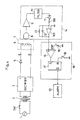
- Fig. 2 is a circuit diagram showing a charge detecting apparatus embodying the present invention.
- numeral 1 denotes a commercial power source
- numeral 2 a transformer
- numeral 3 a rectifier including a diode bridge and a smoothing capacitor for effecting full-wave rectification.
- the collector of an NPN-type switching transistor 4 is connected to a positive terminal of the rectifier 3.
- the emitter of the transistor 4 is connected to one charging terminal a through a reverse flow checking diode 5.
- the other charging terminal b is connected to a negative terminal of the rectifier 3.
- the two terminals of a secondary battery 6 are connected to the charging terminals a and b.
- an electrostatic microphone 8 for example, is placed in contact with an outside position of a container 7 containing the secondary battery 6 for picking up bubbling sounds produced inside the secondary battery 6.
- the electrostatic microphone 8 is attached peripherally of the container 7 through a suction cup having a sound absorbing function, for example.
- the bubbling sounds are picked up preferably with the secondary battery 6 carrying the electrostatic microphone 8 and mounted in a box which is effective to shut off ambient noise.
- the electrostatic microphone 8 is connected to an amplifier 9 which is connected to a filter 10.
- the filter 10 is followed by a rectifying device, e.g. a rectifying diode 11 and a resistor 100.
- a rectifying device e.g. a rectifying diode 11 and a resistor 100.
- an integrating circuit acting as a smoothing device is connected, which includes an operational amplifier 101, an integrating capacitor 12 and a discharge resistor 13.
- the electrostatic microphone 8, amplifier 9, filter 10, rectifying diode 11, resistor 100, integrating capacitor 12, operational amplifier 101 and discharge resistor 13 constitute a bubbling sound detecting device 14.
- An output of the operational amplifier 101 in the bubbling sound detecting device 14 is connected to a non-inversion input terminal (+) of a comparator 15.
- An inversion input terminal (-) of the comparator 15 is connected to a voltage variable reference source 16 which produces a reference voltage Vref.
- An output terminal of the comparator 15 is connected to a set input terminal S of a flip-flop 17.
- a reset input terminal R of the flip-flop 17 is grounded through a reset switch 18.
- a Q output terminal of the flip-flop 17 is connected to the base of the switching transistor 4.
- the comparator 15, reference source 16, flip-flop 17 and reset switch 18 constitute a bubble quantity checking device 19.
- the reference voltage Vref of the reference source 16 for setting to the comparator 15 in the bubble quantity checking device 19 is predetermined to correspond to an output voltage of the integrating capacitor 12 occurring at charge completion time and in accordance with the type, capacity and the like of the secondary battery 6 to be charged.
- the reset switch 18 of the flip-flop 17 When starting a charging operation, the reset switch 18 of the flip-flop 17 is temporarily turned on to place the Q output terminal of the flip-flop 17 in "H” level. As a result, the switching transistor 4 becomes conductive to start charging the secondary battery 6. The reset switch 18 is thereafter turned off but the Q output terminal of the flip-flop 17 remains "H" level.
- the current output from the positive terminal of the rectifier 3 charges the secondary battery 6 by flowing through the switching transistor 4, reverse flow checking diode 5, charging terminal a, secondary battery 6 and charging terminal b to the negative terminal of the rectifier 3.
- the switching transistor 4 is fully conductive with application of a sufficient base current thereof, to give a sufficiently large value to the charge current for the secondary battery 6. This value is dependent on the secondary output voltage and internal resistance of the transformer 2, voltage drop at the diode 5, voltage of the secondary battery 6 during the charging, and so on. Thus, the value of the charge current may be determined by selecting the internal resistance of the transformer 2.
- the terminal voltage of the secondary battery 6 gradually increases with progress of charging.
- This detection current is amplified by the amplifier 9.
- the filter 10 extracts only components in a frequency band of the bubbling sounds from the current, discarding frequency components of other sounds.
- a bubbling sound detection signal emerging from the filter 10 is an AC signal which is rectified by the rectifying diode 11 and resistor 100. This signal is then smoothed and converted into a DC signal by the integrating circuit including the integrating capacitor 12 and operational amplifier 101.
- the quantity of bubbles formed in the secondary battery 6 near the charge completion time T0 is little influenced by the battery temperature.
- the increase in the output voltage of the integrating capacitor 12 of the bubbling sound detecting device 14 remains steady regardless of the temperature.
- charging is automatically stopped by the charge completion signal applied from the bubble quantity checking device 19 to the switching transistor 4.
- the charge completion signal may be transmitted to an alarm 20 such as a buzzer or a lamp to operate the alarm 20 for notifying the operator of completion of charging. Then the operator may turn off a source switch SW of the commercial power source 1 to stop the charging of the secondary battery 6.
- An alarm as shown in Fig. 4 may be added to the charge detecting apparatus shown in Fig. 2, whereby the charging current is cut upon completion of charging and at the same time the alarm is operated to notify the operator of the completion.
Landscapes
- Physics & Mathematics (AREA)
- General Physics & Mathematics (AREA)
- Charge And Discharge Circuits For Batteries Or The Like (AREA)
- Secondary Cells (AREA)
- Tests Of Electric Status Of Batteries (AREA)
Applications Claiming Priority (2)
| Application Number | Priority Date | Filing Date | Title |
|---|---|---|---|
| JP95420/90 | 1990-04-10 | ||
| JP2095420A JPH03293935A (ja) | 1990-04-10 | 1990-04-10 | 充電検出装置 |
Publications (3)
| Publication Number | Publication Date |
|---|---|
| EP0451584A2 true EP0451584A2 (de) | 1991-10-16 |
| EP0451584A3 EP0451584A3 (en) | 1992-07-08 |
| EP0451584B1 EP0451584B1 (de) | 1994-07-27 |
Family
ID=14137202
Family Applications (1)
| Application Number | Title | Priority Date | Filing Date |
|---|---|---|---|
| EP91104604A Expired - Lifetime EP0451584B1 (de) | 1990-04-10 | 1991-03-23 | Ladungsbestimmungsanordnung |
Country Status (4)
| Country | Link |
|---|---|
| US (1) | US5126649A (de) |
| EP (1) | EP0451584B1 (de) |
| JP (1) | JPH03293935A (de) |
| DE (1) | DE69103064T2 (de) |
Cited By (4)
| Publication number | Priority date | Publication date | Assignee | Title |
|---|---|---|---|---|
| EP0957560A3 (de) * | 1998-05-11 | 2000-12-13 | Matsushita Electric Industrial Co., Ltd. | Verfahren zum Detektion des Volladezustandes eines Sekundärbatterie und Detektor der dieses verwendet |
| FR2949908A1 (fr) * | 2009-09-04 | 2011-03-11 | Commissariat Energie Atomique | Procede de charge d'un accumulateur electrochimique |
| CN102244398A (zh) * | 2011-02-24 | 2011-11-16 | 广东志成冠军集团有限公司 | 一种零损耗的光伏太阳能充电控制装置及实现方法 |
| FR3010577A1 (fr) * | 2013-09-12 | 2015-03-13 | IFP Energies Nouvelles | Dispositif et procede de regeneration de batterie pilote par une mesure d'emission acoustique |
Families Citing this family (12)
| Publication number | Priority date | Publication date | Assignee | Title |
|---|---|---|---|---|
| US5424488A (en) * | 1993-06-07 | 1995-06-13 | Aphex Systems, Ltd. | Transient discriminate harmonics generator |
| US5742147A (en) * | 1994-04-25 | 1998-04-21 | Molina; Daniel Ralph | Dc based powering and charging circuit for compressor systems and other mechanical devices |
| EP1164680B1 (de) * | 2000-04-28 | 2016-08-10 | Panasonic Corporation | Ladeverfahren für Batteriesatz mit einer Vielzahl Batterieeinheiten |
| ATE499054T1 (de) * | 2000-12-20 | 2011-03-15 | Fox Hollow Technologies Inc | Verkleinerungskatheter |
| DE102004063350A1 (de) * | 2004-12-23 | 2006-07-06 | Braun Gmbh | Elektrokleingerät mit einem aufladbaren Energiespeicher und einer Anzeige für den Ladezustand des Energiespeichers |
| DE102005006303B4 (de) * | 2005-02-11 | 2012-09-20 | Industrie Automation Energiesysteme Ag | Einrichtung zur Überwachung der Gasungsspannung von Akkumulatoren |
| CN101960655A (zh) * | 2008-03-04 | 2011-01-26 | 埃纳德尔公司 | 锂离电池阳极及其制造方法 |
| JP2016057264A (ja) * | 2014-09-12 | 2016-04-21 | Ntn株式会社 | バッテリーチェッカー |
| JP6662319B2 (ja) | 2017-02-03 | 2020-03-11 | オムロン株式会社 | 異常検出装置 |
| CN110601303B (zh) * | 2019-09-25 | 2022-04-08 | 维沃移动通信有限公司 | 充电电路、充电保护方法及移动终端 |
| JP7514725B2 (ja) * | 2020-10-15 | 2024-07-11 | 日本特殊陶業株式会社 | 二次電池の取扱方法及び二次電池の取扱システム |
| CN114050574B (zh) * | 2021-11-29 | 2022-08-16 | 国网江苏省电力有限公司扬州市江都区供电分公司 | 一种智能低压切换系统及其控制方法 |
Family Cites Families (9)
| Publication number | Priority date | Publication date | Assignee | Title |
|---|---|---|---|---|
| US3548286A (en) * | 1969-03-07 | 1970-12-15 | John R Hollingsworth Co | Gas sensor for battery charger |
| US3584285A (en) * | 1969-12-15 | 1971-06-08 | Yardney Internation Corp | System for charging electric battery cell |
| US3652915A (en) * | 1970-04-02 | 1972-03-28 | Klaus Eberts | Battery charging system with means for sensing current, voltage, gassing and temperature |
| US3781751A (en) * | 1972-05-18 | 1973-12-25 | Dynamic Instr Corp | Pressure transducer |
| US4034279A (en) * | 1973-07-13 | 1977-07-05 | Boliden Aktiebolag | Method and a device for determining gas generation with electrodes in contact with electrolytes |
| GB1486425A (en) * | 1973-12-21 | 1977-09-21 | Macharg J A | Control systems for battery charges |
| US4366431A (en) * | 1980-12-03 | 1982-12-28 | Ehv Systems, Inc. | Battery gassing detector |
| US4388583A (en) * | 1981-03-06 | 1983-06-14 | Outboard Marine Corporation | Battery charger with transducer for controlling charge rate |
| US4551667A (en) * | 1983-07-07 | 1985-11-05 | Outboard Marine Corporation | Gas controlled battery charging system using a gas detector |
-
1990
- 1990-04-10 JP JP2095420A patent/JPH03293935A/ja active Pending
-
1991
- 1991-03-21 US US07/672,803 patent/US5126649A/en not_active Expired - Fee Related
- 1991-03-23 DE DE69103064T patent/DE69103064T2/de not_active Expired - Fee Related
- 1991-03-23 EP EP91104604A patent/EP0451584B1/de not_active Expired - Lifetime
Cited By (5)
| Publication number | Priority date | Publication date | Assignee | Title |
|---|---|---|---|---|
| EP0957560A3 (de) * | 1998-05-11 | 2000-12-13 | Matsushita Electric Industrial Co., Ltd. | Verfahren zum Detektion des Volladezustandes eines Sekundärbatterie und Detektor der dieses verwendet |
| FR2949908A1 (fr) * | 2009-09-04 | 2011-03-11 | Commissariat Energie Atomique | Procede de charge d'un accumulateur electrochimique |
| CN102244398A (zh) * | 2011-02-24 | 2011-11-16 | 广东志成冠军集团有限公司 | 一种零损耗的光伏太阳能充电控制装置及实现方法 |
| CN102244398B (zh) * | 2011-02-24 | 2014-04-09 | 广东志成冠军集团有限公司 | 一种零损耗的光伏太阳能充电控制装置及实现方法 |
| FR3010577A1 (fr) * | 2013-09-12 | 2015-03-13 | IFP Energies Nouvelles | Dispositif et procede de regeneration de batterie pilote par une mesure d'emission acoustique |
Also Published As
| Publication number | Publication date |
|---|---|
| US5126649A (en) | 1992-06-30 |
| DE69103064D1 (de) | 1994-09-01 |
| JPH03293935A (ja) | 1991-12-25 |
| EP0451584B1 (de) | 1994-07-27 |
| EP0451584A3 (en) | 1992-07-08 |
| DE69103064T2 (de) | 1995-03-09 |
Similar Documents
| Publication | Publication Date | Title |
|---|---|---|
| US5126649A (en) | Charge detecting apparatus | |
| US3852652A (en) | Rapid battery charging system and method | |
| RU2141155C1 (ru) | Способ и устройство для определения типа внешнего источника электропитания | |
| US4388583A (en) | Battery charger with transducer for controlling charge rate | |
| EP0293664A2 (de) | Universalverfahren und -vorrichtung zur Ladung einer Batterie | |
| US5093624A (en) | Battery monitoring | |
| JPH06217463A (ja) | 電池を電源とする電子装置用の電力管理装置および電池パックにおいて利用可能な電力量を決定する方法 | |
| US5260638A (en) | Method and circuit for quick charging of secondary cell | |
| CN110739751B (zh) | 一种锂电池及其充放电状态监测方法 | |
| JPH08329992A (ja) | 電池パックと充電器 | |
| WO2021077798A1 (zh) | 一种充电方法及充电装置 | |
| US6144188A (en) | Method for detecting fully charged condition of secondary battery and detector using the same | |
| US20020060552A1 (en) | Battery charger capable of accurately determining fully charged condition regardless of batteries with different charge chracteristics | |
| US5691624A (en) | Method and apparatus for detecting a full-charge condition while charging a battery | |
| JPH11187585A (ja) | リチウムイオン2次電池充電器および充電方法 | |
| JP2022544083A (ja) | バッテリー容量インジケータ | |
| JPH0819192A (ja) | 充電装置 | |
| JPH0737621A (ja) | 2次電池の残存容量の判別装置及びこれを用いた充電装置 | |
| JPH08233919A (ja) | 電池種類判別装置 | |
| JP3346821B2 (ja) | 充電装置 | |
| JP3445825B2 (ja) | 二次電池の充電装置 | |
| JPH01138931A (ja) | 充電器の制御回路 | |
| JPH0576140A (ja) | バツテリーチヤージヤ | |
| JP2677071B2 (ja) | 電源装置 | |
| JPH11355968A (ja) | 蓄電池の充電方法とその充電装置 |
Legal Events
| Date | Code | Title | Description |
|---|---|---|---|
| PUAI | Public reference made under article 153(3) epc to a published international application that has entered the european phase |
Free format text: ORIGINAL CODE: 0009012 |
|
| AK | Designated contracting states |
Kind code of ref document: A2 Designated state(s): DE FR GB |
|
| PUAL | Search report despatched |
Free format text: ORIGINAL CODE: 0009013 |
|
| AK | Designated contracting states |
Kind code of ref document: A3 Designated state(s): DE FR GB |
|
| 17P | Request for examination filed |
Effective date: 19920819 |
|
| 17Q | First examination report despatched |
Effective date: 19931206 |
|
| GRAA | (expected) grant |
Free format text: ORIGINAL CODE: 0009210 |
|
| AK | Designated contracting states |
Kind code of ref document: B1 Designated state(s): DE FR GB |
|
| REF | Corresponds to: |
Ref document number: 69103064 Country of ref document: DE Date of ref document: 19940901 |
|
| ET | Fr: translation filed | ||
| PLBE | No opposition filed within time limit |
Free format text: ORIGINAL CODE: 0009261 |
|
| STAA | Information on the status of an ep patent application or granted ep patent |
Free format text: STATUS: NO OPPOSITION FILED WITHIN TIME LIMIT |
|
| 26N | No opposition filed | ||
| PGFP | Annual fee paid to national office [announced via postgrant information from national office to epo] |
Ref country code: GB Payment date: 19960314 Year of fee payment: 6 |
|
| PGFP | Annual fee paid to national office [announced via postgrant information from national office to epo] |
Ref country code: FR Payment date: 19960315 Year of fee payment: 6 |
|
| PGFP | Annual fee paid to national office [announced via postgrant information from national office to epo] |
Ref country code: DE Payment date: 19960328 Year of fee payment: 6 |
|
| PG25 | Lapsed in a contracting state [announced via postgrant information from national office to epo] |
Ref country code: GB Effective date: 19970323 |
|
| GBPC | Gb: european patent ceased through non-payment of renewal fee |
Effective date: 19970323 |
|
| PG25 | Lapsed in a contracting state [announced via postgrant information from national office to epo] |
Ref country code: FR Free format text: LAPSE BECAUSE OF NON-PAYMENT OF DUE FEES Effective date: 19971128 |
|
| PG25 | Lapsed in a contracting state [announced via postgrant information from national office to epo] |
Ref country code: DE Effective date: 19971202 |
|
| REG | Reference to a national code |
Ref country code: FR Ref legal event code: ST |