EP0451584A2 - Charge detecting apparatus - Google Patents
Charge detecting apparatus Download PDFInfo
- Publication number
- EP0451584A2 EP0451584A2 EP91104604A EP91104604A EP0451584A2 EP 0451584 A2 EP0451584 A2 EP 0451584A2 EP 91104604 A EP91104604 A EP 91104604A EP 91104604 A EP91104604 A EP 91104604A EP 0451584 A2 EP0451584 A2 EP 0451584A2
- Authority
- EP
- European Patent Office
- Prior art keywords
- bubbling
- secondary battery
- charging
- battery
- charge
- Prior art date
- Legal status (The legal status is an assumption and is not a legal conclusion. Google has not performed a legal analysis and makes no representation as to the accuracy of the status listed.)
- Granted
Links
Images


Classifications
-
- G—PHYSICS
- G01—MEASURING; TESTING
- G01R—MEASURING ELECTRIC VARIABLES; MEASURING MAGNETIC VARIABLES
- G01R31/00—Arrangements for testing electric properties; Arrangements for locating electric faults; Arrangements for electrical testing characterised by what is being tested not provided for elsewhere
- G01R31/36—Arrangements for testing, measuring or monitoring the electrical condition of accumulators or electric batteries, e.g. capacity or state of charge [SoC]
- G01R31/378—Arrangements for testing, measuring or monitoring the electrical condition of accumulators or electric batteries, e.g. capacity or state of charge [SoC] specially adapted for the type of battery or accumulator
Definitions
- the present invention relates to a charge detecting apparatus for detecting charge completion time when charging a secondary battery in which an electrolyte is used.
- the constant-voltage charging is not suited for rapid charging in that, although a battery may be charged by means of a large quantity of current in an initial stage of charging, only a small quantity of current may be used in later stages.
- the method suited for rapid charging is the constant-current charging which allows a large and constant quantity of current to be supplied from beginning to end of charging.
- This method detects a voltage between the terminals of a secondary battery, and charging is regarded as being completed when the gradient (time variation rate) of this voltage reaches a predetermined level.
- This method utilizes bubbles produced internally of a battery when charging is completed, and charging is regarded as being completed when the internal gas pressure of a battery having a special, enclosed structure reaches a predetermined level.
- Fig. 1 shows temperature characteristics of the voltage between the terminals of a lead storage battery.
- the horizontal axis represents charging time.
- the voltage between the terminals shows a sharp rise when the battery temperature is low, and the increase becomes moderate with increases in the battery temperature.
- a reference level for determining charge completion must be adjusted in accordance with the battery temperature. Difficulties are encountered particularly when the battery temperature is high since the reference level must be set strictly.
- the reference level may be set on the basis of a temperature detected by this temperature sensor.
- temperatures of the battery and charger may be different, whereby the reference level set could be grossly inappropriate.
- charging may be continued after the charge completion time T0. This results in an overcharge which not only overheats the battery but adds difficulty to correct detection of the charge completion time T0. If the charging is allowed to continue, the electrolyte in the battery undergoes electrolysis to be released as hydrogen gas and oxygen gas. As a result, the battery may lose its function altogether.
- the bubbling is visually monitored instead of detecting the internal pressure, and charging is stopped upon detection of a predetermined quantity of bubbles.
- this method is limited to batteries mounted in transparent containers such as car batteries whose interiors may be observed from outside, and is not applicable to lead storage batteries, nickel-cadmium batteries or alkaline storage batteries encased in opaque containers.
- the present invention has been made having regard to the state of the art noted above, and its object is to provide a charge detecting apparatus capable of detecting charge completion time relatively simply and correctly regardless of types of secondary batteries and without the influences of temperature variations.
- a charge detecting apparatus for detecting completion of charging of a secondary battery in which an electrolyte is used, the apparatus comprising; a bubbling sound detecting device for picking up, with a microphone or the like externally of a container of the secondary battery, bubbling sounds produced inside the secondary battery, and converting the bubbling sounds into a quantity of electricity, and a bubble quantity checking device for outputting a charge completion signal when the quantity of electricity output from the bubbling sound detecting device reaches a predetermined reference level.
- the present invention performs the following functions:
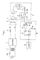
- Fig. 2 is a circuit diagram showing a charge detecting apparatus embodying the present invention.
- numeral 1 denotes a commercial power source
- numeral 2 a transformer
- numeral 3 a rectifier including a diode bridge and a smoothing capacitor for effecting full-wave rectification.
- the collector of an NPN-type switching transistor 4 is connected to a positive terminal of the rectifier 3.
- the emitter of the transistor 4 is connected to one charging terminal a through a reverse flow checking diode 5.
- the other charging terminal b is connected to a negative terminal of the rectifier 3.
- the two terminals of a secondary battery 6 are connected to the charging terminals a and b.
- an electrostatic microphone 8 for example, is placed in contact with an outside position of a container 7 containing the secondary battery 6 for picking up bubbling sounds produced inside the secondary battery 6.
- the electrostatic microphone 8 is attached peripherally of the container 7 through a suction cup having a sound absorbing function, for example.
- the bubbling sounds are picked up preferably with the secondary battery 6 carrying the electrostatic microphone 8 and mounted in a box which is effective to shut off ambient noise.
- the electrostatic microphone 8 is connected to an amplifier 9 which is connected to a filter 10.
- the filter 10 is followed by a rectifying device, e.g. a rectifying diode 11 and a resistor 100.
- a rectifying device e.g. a rectifying diode 11 and a resistor 100.
- an integrating circuit acting as a smoothing device is connected, which includes an operational amplifier 101, an integrating capacitor 12 and a discharge resistor 13.
- the electrostatic microphone 8, amplifier 9, filter 10, rectifying diode 11, resistor 100, integrating capacitor 12, operational amplifier 101 and discharge resistor 13 constitute a bubbling sound detecting device 14.
- An output of the operational amplifier 101 in the bubbling sound detecting device 14 is connected to a non-inversion input terminal (+) of a comparator 15.
- An inversion input terminal (-) of the comparator 15 is connected to a voltage variable reference source 16 which produces a reference voltage Vref.
- An output terminal of the comparator 15 is connected to a set input terminal S of a flip-flop 17.
- a reset input terminal R of the flip-flop 17 is grounded through a reset switch 18.
- a Q output terminal of the flip-flop 17 is connected to the base of the switching transistor 4.
- the comparator 15, reference source 16, flip-flop 17 and reset switch 18 constitute a bubble quantity checking device 19.
- the reference voltage Vref of the reference source 16 for setting to the comparator 15 in the bubble quantity checking device 19 is predetermined to correspond to an output voltage of the integrating capacitor 12 occurring at charge completion time and in accordance with the type, capacity and the like of the secondary battery 6 to be charged.
- the reset switch 18 of the flip-flop 17 When starting a charging operation, the reset switch 18 of the flip-flop 17 is temporarily turned on to place the Q output terminal of the flip-flop 17 in "H” level. As a result, the switching transistor 4 becomes conductive to start charging the secondary battery 6. The reset switch 18 is thereafter turned off but the Q output terminal of the flip-flop 17 remains "H" level.
- the current output from the positive terminal of the rectifier 3 charges the secondary battery 6 by flowing through the switching transistor 4, reverse flow checking diode 5, charging terminal a, secondary battery 6 and charging terminal b to the negative terminal of the rectifier 3.
- the switching transistor 4 is fully conductive with application of a sufficient base current thereof, to give a sufficiently large value to the charge current for the secondary battery 6. This value is dependent on the secondary output voltage and internal resistance of the transformer 2, voltage drop at the diode 5, voltage of the secondary battery 6 during the charging, and so on. Thus, the value of the charge current may be determined by selecting the internal resistance of the transformer 2.
- the terminal voltage of the secondary battery 6 gradually increases with progress of charging.
- This detection current is amplified by the amplifier 9.
- the filter 10 extracts only components in a frequency band of the bubbling sounds from the current, discarding frequency components of other sounds.
- a bubbling sound detection signal emerging from the filter 10 is an AC signal which is rectified by the rectifying diode 11 and resistor 100. This signal is then smoothed and converted into a DC signal by the integrating circuit including the integrating capacitor 12 and operational amplifier 101.
- the quantity of bubbles formed in the secondary battery 6 near the charge completion time T0 is little influenced by the battery temperature.
- the increase in the output voltage of the integrating capacitor 12 of the bubbling sound detecting device 14 remains steady regardless of the temperature.
- charging is automatically stopped by the charge completion signal applied from the bubble quantity checking device 19 to the switching transistor 4.
- the charge completion signal may be transmitted to an alarm 20 such as a buzzer or a lamp to operate the alarm 20 for notifying the operator of completion of charging. Then the operator may turn off a source switch SW of the commercial power source 1 to stop the charging of the secondary battery 6.
- An alarm as shown in Fig. 4 may be added to the charge detecting apparatus shown in Fig. 2, whereby the charging current is cut upon completion of charging and at the same time the alarm is operated to notify the operator of the completion.
Landscapes
- Physics & Mathematics (AREA)
- General Physics & Mathematics (AREA)
- Charge And Discharge Circuits For Batteries Or The Like (AREA)
- Secondary Cells (AREA)
- Tests Of Electric Status Of Batteries (AREA)
Abstract
Description
- The present invention relates to a charge detecting apparatus for detecting charge completion time when charging a secondary battery in which an electrolyte is used.
- Conventional methods of charging secondary batteries are broadly classified into constant-voltage charging and constant-current charging. Methods of detecting charge completion time include detection of terminal voltage, detection of terminal voltage variations and detection of a battery internal pressure.
- The constant-voltage charging is not suited for rapid charging in that, although a battery may be charged by means of a large quantity of current in an initial stage of charging, only a small quantity of current may be used in later stages. The method suited for rapid charging is the constant-current charging which allows a large and constant quantity of current to be supplied from beginning to end of charging.
- However, the constant-current charging always requires some means to prevent an overcharge. It is therefore necessary to check whether a battery is fully charged or not. Broadly, there are the following three methods for determining the fully charged state of a battery:
- This is a method in which charging is regarded as being completed when the terminal voltage of a battery being charged reaches a predetermined level.
- This method detects a voltage between the terminals of a secondary battery, and charging is regarded as being completed when the gradient (time variation rate) of this voltage reaches a predetermined level.
- This method utilizes bubbles produced internally of a battery when charging is completed, and charging is regarded as being completed when the internal gas pressure of a battery having a special, enclosed structure reaches a predetermined level.
- Features of these methods will be described hereunder.
- The voltage between the terminals of a secondary battery is greatly influenced by the temperature of the battery during charging. Fig. 1 shows temperature characteristics of the voltage between the terminals of a lead storage battery. The horizontal axis represents charging time.
- At charge completion time T0, the voltage between the terminals shows a sharp rise when the battery temperature is low, and the increase becomes moderate with increases in the battery temperature. Thus, a reference level for determining charge completion must be adjusted in accordance with the battery temperature. Difficulties are encountered particularly when the battery temperature is high since the reference level must be set strictly.
- In the case of a charger having a built-in temperature sensor, the reference level may be set on the basis of a temperature detected by this temperature sensor. However, temperatures of the battery and charger may be different, whereby the reference level set could be grossly inappropriate.
- With an incorrect adjustment of the reference level for determining the voltage between the terminals, charging may be continued after the charge completion time T0. This results in an overcharge which not only overheats the battery but adds difficulty to correct detection of the charge completion time T0. If the charging is allowed to continue, the electrolyte in the battery undergoes electrolysis to be released as hydrogen gas and oxygen gas. As a result, the battery may lose its function altogether.
- In utilizing bubbling that takes place inside a battery at charge completion time, it is necessary to set a pressure sensor inside the battery and seal the entire battery tight. Since a battery having such a special structure is required, this method is little used in practice.
- Generally, the bubbling is visually monitored instead of detecting the internal pressure, and charging is stopped upon detection of a predetermined quantity of bubbles. However, this method is limited to batteries mounted in transparent containers such as car batteries whose interiors may be observed from outside, and is not applicable to lead storage batteries, nickel-cadmium batteries or alkaline storage batteries encased in opaque containers.
- The present invention has been made having regard to the state of the art noted above, and its object is to provide a charge detecting apparatus capable of detecting charge completion time relatively simply and correctly regardless of types of secondary batteries and without the influences of temperature variations.
- The above object is fulfilled, according to the present invention, by a charge detecting apparatus for detecting completion of charging of a secondary battery in which an electrolyte is used, the apparatus comprising;
a bubbling sound detecting device for picking up, with a microphone or the like externally of a container of the secondary battery, bubbling sounds produced inside the secondary battery, and converting the bubbling sounds into a quantity of electricity, and
a bubble quantity checking device for outputting a charge completion signal when the quantity of electricity output from the bubbling sound detecting device reaches a predetermined reference level. - The present invention performs the following functions:
- (1) The bubbling sound detecting device is disposed outwardly of the container of a secondary battery for detecting bubbling sounds produced inside the secondary battery. It is therefore unnecessary to set a bubbling sound detecting microphone inside the battery or for an entire battery to have a tight-sealed structure as required in the known method of detecting the internal pressure of a battery described hereinbefore. Further, the secondary battery need not be mounted in a transparent container as required in visual confirmation of bubbling. The present invention is applicable to various types of batteries including open type lead storage batteries, enclosed lead storage batteries, nickel-cadmium batteries and alkaline storage batteries as long as bubbles are formed therein near charge completion time.
- (2) The bubble quantity checking device outputs a charge completion signal when the quantity of electricity received from the bubbling sound detecting device reaches a predetermined reference level. This charge completion signal may be used to automatically stop charging or to drive an alarm to notify the operator of completion of the charging.
- (3) The time variation rate of bubbling quantity is steady near the charge completion time, little affected by variations in the battery temperature, and yet rises relatively rapidly. Consequently, a great degree of precision is not required of the reference level for enabling the bubble quantity checking device to determine the charge completion time. This feature allows the reference setting arrangement to be simple, and the charge completion time to be detected accurately.
- (4) Since the charge completion time of the secondary battery is detected automatically and accurately without the influences of the battery temperature, there is little chance of the electrolyte being exhausted or consumed in a large quantity through the electrolysis caused by an overcharge. Thus, the secondary battery may be charged rapidly with a large quantity of current.
- For the purpose of illustrating the invention, there are shown in the drawings several forms which are presently preferred, it being understood, however, that the invention is not limited to the precise arrangements and instrumentalities shown.
- Fig. 1 is a view showing temperature characteristics of a voltage between terminals in a conventional method of detecting the voltage between terminals,
- Fig. 2 is a circuit diagram showing an electric construction of a charge detecting apparatus in one embodiment of the present invention (an example of nickel-cadmium batteries),
- Fig. 3 is a time chart for illustrating operation of the apparatus shown in Fig. 2, and
- Fig. 4 is a circuit diagram showing an electric construction of a charge detecting apparatus in another embodiment of the present invention.
- Embodiments of the present invention will be described in detail hereinafter with reference to the drawings.
- Fig. 2 is a circuit diagram showing a charge detecting apparatus embodying the present invention.
- In Fig. 2,
numeral 1 denotes a commercial power source, numeral 2 a transformer, and numeral 3 a rectifier including a diode bridge and a smoothing capacitor for effecting full-wave rectification. The collector of an NPN-type switching transistor 4 is connected to a positive terminal of therectifier 3. The emitter of thetransistor 4 is connected to one charging terminal a through a reverseflow checking diode 5. The other charging terminal b is connected to a negative terminal of therectifier 3. The two terminals of asecondary battery 6 are connected to the charging terminals a and b. - With the
secondary battery 6 connected in this way, anelectrostatic microphone 8, for example, is placed in contact with an outside position of acontainer 7 containing thesecondary battery 6 for picking up bubbling sounds produced inside thesecondary battery 6. Theelectrostatic microphone 8 is attached peripherally of thecontainer 7 through a suction cup having a sound absorbing function, for example. The bubbling sounds are picked up preferably with thesecondary battery 6 carrying theelectrostatic microphone 8 and mounted in a box which is effective to shut off ambient noise. - The
electrostatic microphone 8 is connected to anamplifier 9 which is connected to afilter 10. Thefilter 10 is followed by a rectifying device, e.g. a rectifyingdiode 11 and aresistor 100. Further, an integrating circuit acting as a smoothing device is connected, which includes anoperational amplifier 101, an integratingcapacitor 12 and adischarge resistor 13. - The
electrostatic microphone 8,amplifier 9,filter 10, rectifyingdiode 11,resistor 100, integratingcapacitor 12,operational amplifier 101 and dischargeresistor 13 constitute a bubblingsound detecting device 14. - An output of the
operational amplifier 101 in the bubblingsound detecting device 14 is connected to a non-inversion input terminal (+) of acomparator 15. An inversion input terminal (-) of thecomparator 15 is connected to a voltagevariable reference source 16 which produces a reference voltage Vref. An output terminal of thecomparator 15 is connected to a set input terminal S of a flip-flop 17. A reset input terminal R of the flip-flop 17 is grounded through a reset switch 18. AQ output terminal of the flip-flop 17 is connected to the base of the switchingtransistor 4. Thecomparator 15,reference source 16, flip-flop 17 and reset switch 18 constitute a bubblequantity checking device 19. - The way in which the charge detecting apparatus as constructed above operates will be described next.
- The reference voltage Vref of the
reference source 16 for setting to thecomparator 15 in the bubblequantity checking device 19 is predetermined to correspond to an output voltage of the integratingcapacitor 12 occurring at charge completion time and in accordance with the type, capacity and the like of thesecondary battery 6 to be charged. - When starting a charging operation, the reset switch 18 of the flip-
flop 17 is temporarily turned on to place theQ output terminal of the flip-flop 17 in "H" level. As a result, the switchingtransistor 4 becomes conductive to start charging thesecondary battery 6. The reset switch 18 is thereafter turned off but theQ output terminal of the flip-flop 17 remains "H" level. - The operation from beginning to end of the charging will be described hereinafter with reference to the time chart of Fig. 3.
- The current output from the positive terminal of the
rectifier 3 charges thesecondary battery 6 by flowing through the switchingtransistor 4, reverseflow checking diode 5, charging terminal a,secondary battery 6 and charging terminal b to the negative terminal of therectifier 3. The switchingtransistor 4 is fully conductive with application of a sufficient base current thereof, to give a sufficiently large value to the charge current for thesecondary battery 6. This value is dependent on the secondary output voltage and internal resistance of thetransformer 2, voltage drop at thediode 5, voltage of thesecondary battery 6 during the charging, and so on. Thus, the value of the charge current may be determined by selecting the internal resistance of thetransformer 2. The terminal voltage of thesecondary battery 6 gradually increases with progress of charging. - As the charging of the
secondary battery 6 draws toward the end, bubbles begin to form inside thesecondary battery 6. The bubbling occurs only in trace quantities or sporadically first, which gradually increases and ultimately reaches a great degree of intensity. - The
electrostatic microphone 8 of the bubblingsound detecting device 14, placed in contact with thecontainer 7 of thesecondary battery 6, effectively picks up the bubbling sounds in thesecondary battery 6 and converts the sounds into an electric current. This detection current is amplified by theamplifier 9. Thereafter, thefilter 10 extracts only components in a frequency band of the bubbling sounds from the current, discarding frequency components of other sounds. A bubbling sound detection signal emerging from thefilter 10 is an AC signal which is rectified by the rectifyingdiode 11 andresistor 100. This signal is then smoothed and converted into a DC signal by the integrating circuit including the integratingcapacitor 12 andoperational amplifier 101. - DC output of the
operational amplifier 101 increases with the increase in the quantity of bubbles formed. When this output reaches the reference voltage Vref of thereference source 16, the output terminal of thecomparator 15 changes from "L" level to "H" level. As a result, theQ output terminal of the flip-flop 17 changes from "H" level to "L" level. The "L" level output of the flip-flop 17 is applied as a charge completion signal to the base of the switchingtransistor 4. Thereupon the switchingtransistor 4 becomes nonconductive to discontinue the charging of thesecondary battery 6. - The quantity of bubbles formed in the
secondary battery 6 near the charge completion time T0 is little influenced by the battery temperature. Thus, the increase in the output voltage of the integratingcapacitor 12 of the bubblingsound detecting device 14 remains steady regardless of the temperature. This allows the flip-flop 17 of the bubblequantity checking device 19 to output the charge completion signal to the switchingtransistor 4 with a substantially fixed timing regardless of the battery temperature. This timing, therefore, is valid as representing the charge completion time T0. This means that thesecondary battery 6 may be charged with a large quantity of current without being overcharged. - In the foregoing embodiment, charging is automatically stopped by the charge completion signal applied from the bubble
quantity checking device 19 to the switchingtransistor 4. The present invention is not limited to this construction. As shown in Fig. 4, the charge completion signal may be transmitted to analarm 20 such as a buzzer or a lamp to operate thealarm 20 for notifying the operator of completion of charging. Then the operator may turn off a source switch SW of thecommercial power source 1 to stop the charging of thesecondary battery 6. - An alarm as shown in Fig. 4 may be added to the charge detecting apparatus shown in Fig. 2, whereby the charging current is cut upon completion of charging and at the same time the alarm is operated to notify the operator of the completion.
- The present invention may be embodied in other specific forms without departing from the spirit or essential attributes thereof and, accordingly, reference should be made to the appended claims, rather than to the foregoing specification, as indicating the scope of the invention.
Claims (5)
- A charge detecting apparatus for detecting completion of charging of a secondary battery in which an electrolyte is used, said apparatus comprising;
bubbling sound detecting means for picking up, externally of a container of said secondary battery, bubbling sounds produced inside said secondary battery, and converting the bubbling sounds into a quantity of electricity, and
bubble quantity checking means for outputting a charge completion signal when the quantity of electricity output from said bubbling sound detecting means reaches a predetermined reference level. - An apparatus as claimed in claim 1, wherein said bubbling sound detecting means includes;
a microphone disposed in contact with a peripheral surface of said container for detecting the bubbling sounds,
an amplifier for amplifying a detection signal received from said microphone,
a filter for selectively allowing passage of frequency components corresponding to the bubbling sounds in the detection signal amplified by said amplifier,
rectifying means for rectifying the components having passed through said filter, and
smoothing means for smoothing the components having passed through said rectifying means. - An apparatus as claimed in claim 2, wherein said bubble quantity checking means includes;
a comparator for comparing a signal smoothed by said smoothing means with a predetermined reference voltage, and
a flip-flop circuit having an output reversible in response to a signal received from said comparator, a resulting output signal being used as said charge completion signal. - An apparatus as claimed in claim 3, wherein a current supplied to said secondary battery is cut in response to the output signal of said flip-flop circuit.
- An apparatus as claimed in claim 3, further comprising an alarm operable in response to the output signal of said flip-flop circuit.
Applications Claiming Priority (2)
| Application Number | Priority Date | Filing Date | Title |
|---|---|---|---|
| JP95420/90 | 1990-04-10 | ||
| JP2095420A JPH03293935A (en) | 1990-04-10 | 1990-04-10 | Charging detection device |
Publications (3)
| Publication Number | Publication Date |
|---|---|
| EP0451584A2 true EP0451584A2 (en) | 1991-10-16 |
| EP0451584A3 EP0451584A3 (en) | 1992-07-08 |
| EP0451584B1 EP0451584B1 (en) | 1994-07-27 |
Family
ID=14137202
Family Applications (1)
| Application Number | Title | Priority Date | Filing Date |
|---|---|---|---|
| EP91104604A Expired - Lifetime EP0451584B1 (en) | 1990-04-10 | 1991-03-23 | Charge detecting apparatus |
Country Status (4)
| Country | Link |
|---|---|
| US (1) | US5126649A (en) |
| EP (1) | EP0451584B1 (en) |
| JP (1) | JPH03293935A (en) |
| DE (1) | DE69103064T2 (en) |
Cited By (4)
| Publication number | Priority date | Publication date | Assignee | Title |
|---|---|---|---|---|
| EP0957560A3 (en) * | 1998-05-11 | 2000-12-13 | Matsushita Electric Industrial Co., Ltd. | Method for detecting fully charged condition of secondary battery and detector using the same |
| FR2949908A1 (en) * | 2009-09-04 | 2011-03-11 | Commissariat Energie Atomique | Electrochemical battery e.g. nickel-cadmium battery, monitoring method for portable computer, involves directly detecting abnormality within battery as path of harmful chemical reaction within battery or physical degradation of battery |
| CN102244398A (en) * | 2011-02-24 | 2011-11-16 | 广东志成冠军集团有限公司 | A zero-loss photovoltaic solar charging control device and its implementation method |
| FR3010577A1 (en) * | 2013-09-12 | 2015-03-13 | IFP Energies Nouvelles | DEVICE AND METHOD FOR REGENERATING PILOT BATTERY BY ACOUSTIC EMISSION MEASUREMENT |
Families Citing this family (12)
| Publication number | Priority date | Publication date | Assignee | Title |
|---|---|---|---|---|
| US5424488A (en) * | 1993-06-07 | 1995-06-13 | Aphex Systems, Ltd. | Transient discriminate harmonics generator |
| US5742147A (en) * | 1994-04-25 | 1998-04-21 | Molina; Daniel Ralph | Dc based powering and charging circuit for compressor systems and other mechanical devices |
| EP1164680B1 (en) * | 2000-04-28 | 2016-08-10 | Panasonic Corporation | Method for charging a battery pack including a plurality of battery units |
| DE60144107D1 (en) * | 2000-12-20 | 2011-04-07 | Fox Hollow Technologies Inc | REDUCTION CATHETER |
| DE102004063350A1 (en) * | 2004-12-23 | 2006-07-06 | Braun Gmbh | Small domestic appliance with a rechargeable energy storage and an indication of the state of charge of the energy storage |
| DE102005006303B4 (en) * | 2005-02-11 | 2012-09-20 | Industrie Automation Energiesysteme Ag | Device for monitoring the gassing voltage of accumulators |
| US20110008676A1 (en) * | 2008-03-04 | 2011-01-13 | Golovin M Neal | Anode for lithium-ion cell and method of making the same |
| JP2016057264A (en) | 2014-09-12 | 2016-04-21 | Ntn株式会社 | Battery Checker |
| JP6662319B2 (en) * | 2017-02-03 | 2020-03-11 | オムロン株式会社 | Anomaly detection device |
| CN110601303B (en) * | 2019-09-25 | 2022-04-08 | 维沃移动通信有限公司 | Charging circuit, charging protection method and mobile terminal |
| JP7514725B2 (en) * | 2020-10-15 | 2024-07-11 | 日本特殊陶業株式会社 | Secondary battery handling method and secondary battery handling system |
| CN114050574B (en) * | 2021-11-29 | 2022-08-16 | 国网江苏省电力有限公司扬州市江都区供电分公司 | Intelligent low-voltage switching system and control method thereof |
Family Cites Families (9)
| Publication number | Priority date | Publication date | Assignee | Title |
|---|---|---|---|---|
| US3548286A (en) * | 1969-03-07 | 1970-12-15 | John R Hollingsworth Co | Gas sensor for battery charger |
| US3584285A (en) * | 1969-12-15 | 1971-06-08 | Yardney Internation Corp | System for charging electric battery cell |
| US3652915A (en) * | 1970-04-02 | 1972-03-28 | Klaus Eberts | Battery charging system with means for sensing current, voltage, gassing and temperature |
| US3781751A (en) * | 1972-05-18 | 1973-12-25 | Dynamic Instr Corp | Pressure transducer |
| US4034279A (en) * | 1973-07-13 | 1977-07-05 | Boliden Aktiebolag | Method and a device for determining gas generation with electrodes in contact with electrolytes |
| GB1486425A (en) * | 1973-12-21 | 1977-09-21 | Macharg J A | Control systems for battery charges |
| US4366431A (en) * | 1980-12-03 | 1982-12-28 | Ehv Systems, Inc. | Battery gassing detector |
| US4388583A (en) * | 1981-03-06 | 1983-06-14 | Outboard Marine Corporation | Battery charger with transducer for controlling charge rate |
| US4551667A (en) * | 1983-07-07 | 1985-11-05 | Outboard Marine Corporation | Gas controlled battery charging system using a gas detector |
-
1990
- 1990-04-10 JP JP2095420A patent/JPH03293935A/en active Pending
-
1991
- 1991-03-21 US US07/672,803 patent/US5126649A/en not_active Expired - Fee Related
- 1991-03-23 EP EP91104604A patent/EP0451584B1/en not_active Expired - Lifetime
- 1991-03-23 DE DE69103064T patent/DE69103064T2/en not_active Expired - Fee Related
Cited By (5)
| Publication number | Priority date | Publication date | Assignee | Title |
|---|---|---|---|---|
| EP0957560A3 (en) * | 1998-05-11 | 2000-12-13 | Matsushita Electric Industrial Co., Ltd. | Method for detecting fully charged condition of secondary battery and detector using the same |
| FR2949908A1 (en) * | 2009-09-04 | 2011-03-11 | Commissariat Energie Atomique | Electrochemical battery e.g. nickel-cadmium battery, monitoring method for portable computer, involves directly detecting abnormality within battery as path of harmful chemical reaction within battery or physical degradation of battery |
| CN102244398A (en) * | 2011-02-24 | 2011-11-16 | 广东志成冠军集团有限公司 | A zero-loss photovoltaic solar charging control device and its implementation method |
| CN102244398B (en) * | 2011-02-24 | 2014-04-09 | 广东志成冠军集团有限公司 | Zero-loss photovoltaic solar charging control device and implementation method |
| FR3010577A1 (en) * | 2013-09-12 | 2015-03-13 | IFP Energies Nouvelles | DEVICE AND METHOD FOR REGENERATING PILOT BATTERY BY ACOUSTIC EMISSION MEASUREMENT |
Also Published As
| Publication number | Publication date |
|---|---|
| JPH03293935A (en) | 1991-12-25 |
| EP0451584A3 (en) | 1992-07-08 |
| DE69103064T2 (en) | 1995-03-09 |
| DE69103064D1 (en) | 1994-09-01 |
| EP0451584B1 (en) | 1994-07-27 |
| US5126649A (en) | 1992-06-30 |
Similar Documents
| Publication | Publication Date | Title |
|---|---|---|
| US5126649A (en) | Charge detecting apparatus | |
| US3852652A (en) | Rapid battery charging system and method | |
| US4388583A (en) | Battery charger with transducer for controlling charge rate | |
| EP0293664A2 (en) | A universal battery charging system and method | |
| US5093624A (en) | Battery monitoring | |
| JPH06217463A (en) | Determing power quantity usale in power control device for electron device having battey as power supply and battery pack | |
| US5260638A (en) | Method and circuit for quick charging of secondary cell | |
| CN110739751B (en) | Lithium battery and charge and discharge state monitoring method thereof | |
| JPH08329992A (en) | Battery pack and charger | |
| US6144188A (en) | Method for detecting fully charged condition of secondary battery and detector using the same | |
| US6420853B1 (en) | Battery charger capable of accurately determining fully charged condition regardless of batteries with different charge chracteristics | |
| WO2021077798A1 (en) | Charging method and charging apparatus | |
| US5691624A (en) | Method and apparatus for detecting a full-charge condition while charging a battery | |
| JP2022544083A (en) | battery capacity indicator | |
| JP3403309B2 (en) | Charging device | |
| JPH0819192A (en) | Charging apparatus | |
| JPH0737621A (en) | Device for determining remaining capacity of secondary battery and charging device using the same | |
| JPH08233919A (en) | Battery type discriminator | |
| JP3346821B2 (en) | Charging device | |
| JP3445825B2 (en) | Rechargeable battery charger | |
| JPH01138931A (en) | Charger control circuit | |
| JPH0576140A (en) | Battery charger | |
| JP2677071B2 (en) | Power supply | |
| JPH11355968A (en) | Storage battery charging method and its charging device | |
| EP1300920A1 (en) | Device and method for electrical battery type recognition |
Legal Events
| Date | Code | Title | Description |
|---|---|---|---|
| PUAI | Public reference made under article 153(3) epc to a published international application that has entered the european phase |
Free format text: ORIGINAL CODE: 0009012 |
|
| AK | Designated contracting states |
Kind code of ref document: A2 Designated state(s): DE FR GB |
|
| PUAL | Search report despatched |
Free format text: ORIGINAL CODE: 0009013 |
|
| AK | Designated contracting states |
Kind code of ref document: A3 Designated state(s): DE FR GB |
|
| 17P | Request for examination filed |
Effective date: 19920819 |
|
| 17Q | First examination report despatched |
Effective date: 19931206 |
|
| GRAA | (expected) grant |
Free format text: ORIGINAL CODE: 0009210 |
|
| AK | Designated contracting states |
Kind code of ref document: B1 Designated state(s): DE FR GB |
|
| REF | Corresponds to: |
Ref document number: 69103064 Country of ref document: DE Date of ref document: 19940901 |
|
| ET | Fr: translation filed | ||
| PLBE | No opposition filed within time limit |
Free format text: ORIGINAL CODE: 0009261 |
|
| STAA | Information on the status of an ep patent application or granted ep patent |
Free format text: STATUS: NO OPPOSITION FILED WITHIN TIME LIMIT |
|
| 26N | No opposition filed | ||
| PGFP | Annual fee paid to national office [announced via postgrant information from national office to epo] |
Ref country code: GB Payment date: 19960314 Year of fee payment: 6 |
|
| PGFP | Annual fee paid to national office [announced via postgrant information from national office to epo] |
Ref country code: FR Payment date: 19960315 Year of fee payment: 6 |
|
| PGFP | Annual fee paid to national office [announced via postgrant information from national office to epo] |
Ref country code: DE Payment date: 19960328 Year of fee payment: 6 |
|
| PG25 | Lapsed in a contracting state [announced via postgrant information from national office to epo] |
Ref country code: GB Effective date: 19970323 |
|
| GBPC | Gb: european patent ceased through non-payment of renewal fee |
Effective date: 19970323 |
|
| PG25 | Lapsed in a contracting state [announced via postgrant information from national office to epo] |
Ref country code: FR Free format text: LAPSE BECAUSE OF NON-PAYMENT OF DUE FEES Effective date: 19971128 |
|
| PG25 | Lapsed in a contracting state [announced via postgrant information from national office to epo] |
Ref country code: DE Effective date: 19971202 |
|
| REG | Reference to a national code |
Ref country code: FR Ref legal event code: ST |