EP0451497A1 - Method for forming the radiation pattern of an active antenna for radar with electronic scanning, and antenna using this method - Google Patents
Method for forming the radiation pattern of an active antenna for radar with electronic scanning, and antenna using this method Download PDFInfo
- Publication number
- EP0451497A1 EP0451497A1 EP91103216A EP91103216A EP0451497A1 EP 0451497 A1 EP0451497 A1 EP 0451497A1 EP 91103216 A EP91103216 A EP 91103216A EP 91103216 A EP91103216 A EP 91103216A EP 0451497 A1 EP0451497 A1 EP 0451497A1
- Authority
- EP
- European Patent Office
- Prior art keywords
- reception
- antenna
- amplifiers
- transmission
- illumination
- Prior art date
- Legal status (The legal status is an assumption and is not a legal conclusion. Google has not performed a legal analysis and makes no representation as to the accuracy of the status listed.)
- Granted
Links
Images


Classifications
-
- H—ELECTRICITY
- H01—ELECTRIC ELEMENTS
- H01Q—ANTENNAS, i.e. RADIO AERIALS
- H01Q21/00—Antenna arrays or systems
- H01Q21/0006—Particular feeding systems
- H01Q21/0025—Modular arrays
-
- H—ELECTRICITY
- H01—ELECTRIC ELEMENTS
- H01Q—ANTENNAS, i.e. RADIO AERIALS
- H01Q3/00—Arrangements for changing or varying the orientation or the shape of the directional pattern of the waves radiated from an antenna or antenna system
- H01Q3/26—Arrangements for changing or varying the orientation or the shape of the directional pattern of the waves radiated from an antenna or antenna system varying the relative phase or relative amplitude of energisation between two or more active radiating elements; varying the distribution of energy across a radiating aperture
-
- G—PHYSICS
- G01—MEASURING; TESTING
- G01S—RADIO DIRECTION-FINDING; RADIO NAVIGATION; DETERMINING DISTANCE OR VELOCITY BY USE OF RADIO WAVES; LOCATING OR PRESENCE-DETECTING BY USE OF THE REFLECTION OR RERADIATION OF RADIO WAVES; ANALOGOUS ARRANGEMENTS USING OTHER WAVES
- G01S7/00—Details of systems according to groups G01S13/00, G01S15/00, G01S17/00
- G01S7/02—Details of systems according to groups G01S13/00, G01S15/00, G01S17/00 of systems according to group G01S13/00
- G01S7/03—Details of HF subsystems specially adapted therefor, e.g. common to transmitter and receiver
- G01S7/032—Constructional details for solid-state radar subsystems
Definitions
- the invention relates to a method for forming the diagram of a high-performance active antenna for an electronic scanning radar and to an antenna implementing this method.
- Electronic scanning makes it possible to greatly increase the performance of radars, by its flexibility (many operating modes possible) and speed (almost instantaneous movement of the beam).
- MMIC gallium arsenide
- MMIC gallium arsenide
- MAER type modules Active Module Transmission Reception in English “TR module” are generally manufactured by connecting to the same substrate (alumina) of “chips” in gallium arsenide which correspond to each of the elementary functions. These chips are themselves mass produced in “foundry” by doping techniques (diffusion or ion implantation), masking, oxidation ...
- doping techniques diffusion or ion implantation
- masking oxidation ...
- logic integrated circuits with silicon the latter have proven their ability to reduce the costs of dizzyingly, without compromising reliability.
- the invention relates to a method for forming the diagram of the radar antenna, particularly well suited to "active" antennas (with distributed modules including transmit and receive amplifiers).
- the invention therefore relates to a process for synthesizing diagrams at low level of secondary lobes and with variable width by varying the gain of the MAERs only in reception, and by working in transmission at constant level, on the antenna and in the time.
- the invention By adapting the reception diagram to the transmission diagram, very good transmission / reception performances are obtained, and the invention has the fundamental advantage of maintaining an acceptable yield for distributed transmission amplifiers; consumption becomes significantly lower for both airborne radars and space radars.
- the fundamental advantage of the invention is that the gain adjustment of the MAER modules, intervening only in reception, does not affect the consumption of the antenna in any way.
- the power dissipated in addition on the reception channel is negligible compared to that dissipated by the HPA amplifiers; because the level of the received signal, echoed by the pulses, is at least 100 dB below the transmitted signal.
- active modules all identical (for example in MMIC technology), the cost is lowered by the series effect because they can be sized for a power level lower than the maximum level that would require amplifiers with different or variable gain; by operating all HPA amplifiers at the same output power, their efficiency is optimized and consumption is therefore minimized, a critical point for active antennas.
- the beam width can be varied by controlling only the phase shifters, in the same way in transmission and in reception (which limits the rate of reconfigurations).
- an antenna having a non-uniform distribution of the active modules in one of its dimensions which makes it possible to greatly reduce their number.
- the method of the invention is applied in this single plane, the amplitude weighting is then identical in transmission and in reception in the other plane, generated by the spatial distribution of the active modules.
- there is an active antenna whose emission amplifiers all operate at the same level, the law of illumination and the diagram of which are "separable" in each of the two main planes of the antenna (azimuth / elevation).
- the HPA amplifiers operate all and always at the output power. We can therefore maximize this and optimize the yield by making them work in the "compression zone" or "at saturation". We thus have "class B” or “class AB” amplifiers, whose continuous consumption and dissipation are much lower (at fixed Pout) than the amplifiers used in linear zone (class A): the latter method would be essential if the 'We wanted to vary the power-emission.
- the output switch 12 is a double input-double output switch (DPDT) which provides both transmission-reception switching and dual access to the radiating elements (two polarizations: horizontal H and vertical V). It is well suited to an integrated production (MMIC technology) ensuring dimensions and very reduced mass.
- DPDT double input-double output switch
- the method of the invention is applicable for a two-dimensional synthesis where the amplitudes Amn and the phases ⁇ min of all radiating elements are independent, the results obtained are presented in a simplified case, for a rectangular antenna with separable illumination .
- x0z (azimuth) and y0z (elevation) are reduced to a one-dimensional diagram synthesis generated by an alignment of sources ("linear network").
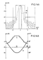
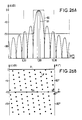
- FIG. 5A presents the emission diagram, obtained with a uniform illumination represented in FIG. 5B (with 128 patch lines), that is to say equi-amplitude (the HPA amplifiers all operate at the same level) and equiphase (to have a fine lobe).
- FIG. 6A presents the reception diagram: the illumination represented in FIG. 6B is always equiphase; a suitable amplitude weighting makes it possible to lower the first secondary lobes relative to the following.
- the curves 80 and 81 shown in parts A of the figures are respectively an outside template, and a corresponding inside template which are imposed.
- FIGS. 8A, 9A and 10 respectively represent reception, emission and emission-reception diagrams. They show that a suitable quantization step, eight levels (therefore three bits) is sufficient to have a law of illumination in reception similar to the "continuous control" case (FIG. 6), and a diagram of similar quality. With 128 omnidirectional sources, 0.57 ⁇ apart, we obtain an overall illumination efficiency that is still just as good (-0.16 dB).
- FIGS. 11A, 12A and 13 which respectively represent transmission, reception, and transmission / reception diagrams, show that even if the number of antenna feed points is greatly reduced (and therefore amplitude controls) and if we maintain a quantization on eight levels, we obtain by the process described above, an equivalent transmission-reception diagram of similar quality.
- it is an active antenna for space SAR of 8.16 meters in length, broken down into 17 48-centimeter sub-panels, which are only amplitude controlled, so as to use identical distributors inside. of all the sub-panels.
- the overall illumination efficiency is slightly worse (-0.18 dB).
- Such a method can be generalized to any number of active modules, beyond a minimum number close to ten on the dimension of the antenna considered.
- This process limits the number of commands to be transmitted to the active modules to the only reconfiguration of the phase shifters: this is in any case necessary for the depointing of the beam, generally linked to its widening. Since the enlargement phase is identical in transmission and reception, the control phase of the phase shifters is moderate.
- the diagram of the enlarged lobe has steeper sides than those of FIG. 16, the discriminating power of the radar is therefore better.
- Some radars only require electronic scanning in one plane, for example the elevation plane in SCAR (Side-looking airbonne radar) or SAR modes.
- FIG. 23 represents a large active antenna (8m32 x 1m91) intended for a space observation radar operating in SAR mode.
- the antenna is broken down into three panels 25, 26 and 27. It has 88 identical horizontal lines 28, as shown in FIG. 24.
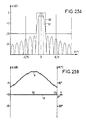
- Each MAER modules 29 are arranged on each horizontal line 28 of radiating elements (here superimposed slot guides 32 and 33, radiating in horizontal polarization, others in vertical polarization). Their non-uniform distribution (closer together in the center) combined with an adjustment of the conductances of the radiating slits to obtain an amplitude law varying linearly in dB from one end to the other, makes it possible to produce a diagram of good quality (FIG. 25).
Abstract
Description
L'invention concerne un procédé de formation du diagramme d'une antenne active à haut rendement pour radar à balayage électronique et une antenne mettant en oeuvre ce procédé.The invention relates to a method for forming the diagram of a high-performance active antenna for an electronic scanning radar and to an antenna implementing this method.
Le balayage électronique permet d'accroître de façon très importante les performances des radars, par sa souplesse (nombreux modes de fonctionnement possible) et la rapidité (déplacement quasi instantané du faisceau).Electronic scanning makes it possible to greatly increase the performance of radars, by its flexibility (many operating modes possible) and speed (almost instantaneous movement of the beam).
Cependant son principal inconvénient est le nombre très élevé de contrôles de phase, et souvent d'amplitude, nécessaires, d'où des pertes, un coût, une masse et une consommation souvent prohibitifs.However, its main drawback is the very high number of phase controls, and often of amplitude, required, resulting in losses, cost, mass and often prohibitive consumption.
Les inconvénients relatifs aux pertes, coût, masse et encombrement ont été surmontés par l'industrialisation en série des circuits intégrés hyperfréquences sur arséniure de gallium (MMIC) : Il est ainsi possible de réaliser de façon très compacte des Modules Actifs Emission-Réception (MAER) qui intègrent les fonctions déphasage, commutation, émission-réception et amplification.The drawbacks relating to losses, cost, mass and size have been overcome by the industrialization in series of microwave integrated circuits on gallium arsenide (MMIC): It is thus possible to produce very compact Active Transmission-Reception Modules (MAER) ) which integrate the phase shift, switching, transmission-reception and amplification functions.
Mais les amplificateurs de puissance-émission en technologie MMIC ont un rendement assez mauvais, qui, de plus, se détériore si l'on fait varier le niveau de la puissance de sortie.However, power transmitting amplifiers in MMIC technology have a rather poor efficiency, which, moreover, deteriorates if the output power level is varied.
Dans les réalisations habituelles, cette variation de niveau est obligatoire :
- aussi bien spatialement pour former un diagramme d'antenne à bas niveau de lobes secondaires ;
- que temporellement, pour moduler la largeur du lobe en l'adaptant à la mission.
- both spatially to form a low level antenna diagram of secondary lobes;
- only temporally, to modulate the width of the lobe by adapting it to the mission.
Il en résulte une consommation prohibitive de ce type d'antenne "active" radar.This results in prohibitive consumption of this type of "active" radar antenna.
Il existe plusieurs documents de l'art connu et notamment
- les articles intitulés "Array Radars : An Update Part 1 - Part II" de Eli Brookner paru dans "Microwave Journal" (Février + Mars 1987) ;
- l'article intitulé "Applicability, Avallability and Affordability of GaAs MMICs In military Systems" de Eugène H. Gregory, paru dans "Microwave Journal" (mars 1987) ;
- l'article intitulé "Affordable MMIC Designs for Phased Arrays" de Ronald J. Naster, Anthony W. Jacomb-Hood et Mark R. Lang, paru dans "Microwave journal" (mars 1987).
- the articles entitled "Array Radars: An Update Part 1 - Part II" by Eli Brookner published in "Microwave Journal" (February + March 1987);
- the article entitled "Applicability, Avallability and Affordability of GaAs MMICs In military Systems" by Eugène H. Gregory, published in "Microwave Journal" (March 1987);
- the article "Affordable MMIC Designs for Phased Arrays" by Ronald J. Naster, Anthony W. Jacomb-Hood and Mark R. Lang, published in "Microwave journal" (March 1987).
Les premiers radars à balayage électronique de l'art connu utilisent des déphaseurs à ferrite ou à diodes pour commander le dépointage du faisceau :
- les déphaseurs à diodes présentent l'inconvénient majeur de pertes importantes (plusieurs dB pour les déphaseurs à 4 ou 5 bits) ce qui oblige à augmenter de beaucoup la puissance des amplificateurs, déjà critiques ;
- les déphaseurs à ferrite présentent des pertes inférieures au dB, mais une masse et un encombrement important. Ces deux paramètres deviennent critiques pour les radars aéroportés, et empêchent leur embarquement sur des satellites.
- diode phase shifters have the major drawback of large losses (several dB for 4 or 5 bit phase shifters) which means that the power of the already critical amplifiers must be greatly increased;
- ferrite phase shifters have losses less than dB, but a large mass and bulk. These two parameters become critical for airborne radars, and prevent them from boarding satellites.
Une étape importante a été franchie avec l'industrialisation de circuits intégrés hyperfréquences sur arséniure de gallium (MMIC ou "Monolythic Microwave Integrated Circuits"). Cette technologie permet de réaliser à très faible masse et encombrement, et à un coût assez réduit en grande série, des circuits hyperfréquences divers ; dont notamment des déphaseurs et des atténuateurs commandables.An important step has been taken with the industrialization of microwave integrated circuits on gallium arsenide (MMIC or "Monolythic Microwave Integrated Circuits"). This technology makes it possible to produce, at very low mass and size, and at a fairly reduced cost in large series, various microwave circuits; including notably phase shifters and controllable attenuators.
L'inconvénient majeur des déphaseurs MMIC est lié à des pertes importantes (plus de 5 dB pour un déphaseur 0-360° à commande analogique ou à 4/5 bits digitaux). Cependant cet aspect devient secondaire lorsque l'on associe ces déphaseurs avec des amplificateurs :
- des amplificateurs HPA (High Power Amplifiers) situés après les déphaseurs en émission. Les pertes interviennent à bas niveau et ne jouent pas sur la limitation en puissance de sortie des amplificateurs : il faut seulement ajouter un peu plus de gain sur les amplificateurs ;
- des amplificateurs LNA (Low Noise Amplifiers) situés avant les déphaseurs en réception. A condition que leur gain soit suffisant (20 à 30 dB), les pertes des déphaseurs ne détériorent quasiment pas le facteur de bruit du récepteur.
- HPA amplifiers (High Power Amplifiers) located after the phase shifters in transmission. The losses occur at low level and do not affect the limitation in power output of the amplifiers: it is only necessary to add a little more gain on the amplifiers;
- LNA amplifiers (Low Noise Amplifiers) located before the phase shifters on reception. Provided that their gain is sufficient (20 to 30 dB), the losses of the phase shifters hardly deteriorate the noise factor of the receiver.
Les modules de type MAER (Module Actif Emission Réception en anglais "TR module") sont en général fabriqués en connectant sur un même substrat (alumine) des "puces" en arséniure de gallium qui correspondent à chacune des fonctions élémentaires. Ces puces sont elles-même fabriquées en série en "fonderie" par des techniques de dopage (diffusion ou implantation ionique), masquage, oxydation ... Inspirées des circuits intégrés logiques au silicium : ces derniers ont prouvé leur capacité à réduire les coûts de façon vertigineuse, sans altérer la fiabilité.MAER type modules (Active Module Transmission Reception in English "TR module") are generally manufactured by connecting to the same substrate (alumina) of "chips" in gallium arsenide which correspond to each of the elementary functions. These chips are themselves mass produced in "foundry" by doping techniques (diffusion or ion implantation), masking, oxidation ... Inspired by logic integrated circuits with silicon: the latter have proven their ability to reduce the costs of dizzyingly, without compromising reliability.
En assemblant plusieurs centaines ou milliers de tels "MMIC-TR modules" dans une antenne radar dite "active" (car elle comprend des amplificateurs qui sont des dispositifs actifs), on parvient ainsi à concilier les exigences du balayage électronique et celle du coût, de la masse et de l'encombrement, critiques pour les radars aéroportés, et encore plus pour les radars spatiaux.By assembling several hundred or thousands of such "MMIC-TR modules" in a so-called "active" radar antenna (since it includes amplifiers which are active devices), it is thus possible to reconcile the requirements of electronic scanning and that of cost, mass and size, critical for airborne radars, and even more for space radars.
Le dernier paramètre critique de telles antennes actives pour radar est leur consommation en énergie continue (D.C. = "direct current" en anglais)The last critical parameter of such active radar antennas is their continuous energy consumption (D.C. = "direct current" in English)
Le rendement des amplificateurs HPA en puissance ajoutée :
Ce rendement est particulièrement mauvais si l'on utilise les amplificateurs HPA en classe A (zone linéaire) en faisant varier la puissance d'entrée, donc de sortie : la consommation est déterminée par les tensions et courants de polarisation, ajustés sur la Pout maximale à sortir. On consomme autant quand on réduit Pin, donc Pout.This efficiency is particularly bad if we use class A HPA amplifiers (linear zone) by varying the input power, therefore output: consumption is determined by the bias voltages and currents, adjusted to the maximum Pout get out. We consume as much when we reduce Pin, so Pout.
Une alternative consiste à faire réduire les tensions de polarisation lorsqu'on veut une Pout plus faible. La consommation diminue ainsi, mais nettement moins (en pourcentage ou dB) que la puissance de sortie. Le rendement η a baisse donc significativement.An alternative is to reduce the bias voltages when you want a lower Pout. Consumption thus decreases, but much less (in percentage or dB) than the output power. The efficiency η has therefore dropped significantly.
Or si l'on veut former des diagrammes d'antenne performants, on doit :
- au minimum avoir une Pout différente suivant le module MAER, de façon à réaliser la pondération nécessaire de l'illumination de l'antenne (en anglais "illumination taper")
- dans certains cas, où la mission nécessite un lobe à largeur modulable, on doit aussi faire varier dans le temps la loi d'illumination en amplitude, donc la Pout des amplificateurs HPA.
- at least have a different Pout depending on the MAER module, so as to achieve the necessary weighting of the antenna illumination (in English "illumination type")
- in certain cases, where the mission requires a lobe with modular width, one must also vary in time the law of illumination in amplitude, therefore the Pout of the amplifiers HPA.
Ainsi les antennes actives radar butent jusqu'ici sur le dilemme suivant : Obtenir un diagramme d'antenne à bas lobes secondaires, et si possible modulable, ne peut se faire qu'en détériorant le rendement des amplificateurs HPA répartis.Thus active radar antennas have hitherto encountered the following dilemma: Obtaining an antenna diagram with low secondary lobes, and if possible modular, can only be achieved by deteriorating the performance of the distributed HPA amplifiers.
L'augmentation induite de la consommation a limité jusqu' ici la généralisation des antennes actives pour les radars aéroportés, et encore plus pour les radars spatiaux ou la puissance disponible est très contingentée.The induced increase in consumption has so far limited the generalization of active antennas for airborne radars, and even more for space radars where the available power is very limited.
Pour sortir de ce dilemme "performances/consommation" l'invention a pour objet un procédé de formation du diagramme de l'antenne radar, particulièrement bien adapté aux antennes "actives" (à modules répartis incluant des amplificateurs émission et réception).To overcome this "performance / consumption" dilemma, the invention relates to a method for forming the diagram of the radar antenna, particularly well suited to "active" antennas (with distributed modules including transmit and receive amplifiers).
L'invention propose, en effet, un procédé de formation du diagramme d'une antenne radar optimisée pour les antennes "actives" à amplificateurs répartis sur l'antenne juste derrière les éléments rayonnants qui permet d'obtenir :
- une dissociation des lois d'illumination, donc des diagrammes, en émission et en réception ;
- une illumination équi-amplitude en émission pour maximiser le rendement des amplificateurs émission tous identiques, et minimiser leur consommation en énergie continue et leur dissipation ; points critiques des antennes actives (fonctionnement en classe B ou AB) ;
- une optimisation de la loi d'illumination en réception par un réglage du gain de la voie réception (atténuateur réglable ou dernier étage de l'amplificateur LNA à gain variable) ;
- une loi de phase identique en émission ou en réception, permettant l'utilisation de déphaseurs réciproques avec un rythme de commande modéré ;
- une synthèse de diagrammes de largeur variable par l'application d'une loi de phase adaptée, sans changer ni la puissance des amplificateurs émission, ni le gain de la voie réception ;
- un contrôle du gain de la voie réception pendant la mission, afin de former des diagrammes élargis à flancs plus raides, et d'améliorer le pouvoir discriminateur des radars.
- a dissociation of the laws of illumination, therefore of the diagrams, in emission and in reception;
- equi-amplitude emission illumination to maximize the efficiency of all identical emission amplifiers, and minimize their continuous energy consumption and dissipation; critical points of active antennas (operation in class B or AB);
- optimization of the reception illumination law by adjusting the gain of the reception channel (adjustable attenuator or last stage of the LNA amplifier with variable gain);
- an identical phase law in transmission or reception, allowing the use of reciprocal phase shifters with a moderate control rhythm;
- a synthesis of variable width diagrams by the application of a suitable phase law, without changing either the power of the transmit amplifiers or the gain of the receive channel;
- a gain control of the reception channel during the mission, in order to form enlarged diagrams with steeper sides, and improve the discriminating power of radars.
Ainsi sur la voie réception des modules de type MAER, on contrôle le gain de façon à former un diagramme réception "adapté au diagramme émission" c'est-à-dire présentant un creux là ou le diagramme émission présente des lobes secondaires gênants ; en effet :
- les performances d'un radar dépendent du produit Ce x Gr (gain émission x gain réception), dans une direction donnée caractérisée par ses angles (ϑ,φ) en coordonnées sphériques.
- les antennes passives réciproques ont le même diagramme en émission et en réception :

- l'antenne active selon l'invention ayant des diagrammes différents présente les mêmes performances qu'une antenne réciproque de diagramme :

Thus on the reception channel of the MAER type modules, the gain is controlled so as to form a reception diagram "adapted to the emission diagram", that is to say having a trough there or the emission diagram has annoying secondary lobes; indeed :
- the performance of a radar depends on the product Ce x Gr (emission gain x reception gain), in a given direction characterized by its angles (ϑ, φ) in spherical coordinates.
- the reciprocal passive antennas have the same diagram in transmission and in reception:
- the active antenna according to the invention having different diagrams has the same performance as a reciprocal diagram antenna:
On appelle Ger le "diagramme équivalent émission-réception".We call Ger the "emission-reception equivalent diagram".
On le compare aux diagrammes obtenus par les méthodes habituelles où Ge est égal à Gr, et on obtient des performances supérieures.We compare it to the diagrams obtained by the usual methods where Ge is equal to Gr, and we obtain superior performances.
L'invention se rapporte donc à un procédé de synthèses de diagrammes à bas niveau de lobes secondaires et à largeur variable en faisant varier le gain des MAER uniquement en réception, et en travaillant en émission à niveau constant, sur l'antenne et dans le temps.The invention therefore relates to a process for synthesizing diagrams at low level of secondary lobes and with variable width by varying the gain of the MAERs only in reception, and by working in transmission at constant level, on the antenna and in the time.
En adaptant le diagramme réception au diagramme émission, on obtient des performances émission/réception très bonnes, et l'invention présente l'avantage fondamental de conserver un rendement acceptable aux amplificateurs émission répartis ; la consommation devient nettement plus faible tant pour les radars aéroportés que pour les radars spatiaux.By adapting the reception diagram to the transmission diagram, very good transmission / reception performances are obtained, and the invention has the fundamental advantage of maintaining an acceptable yield for distributed transmission amplifiers; consumption becomes significantly lower for both airborne radars and space radars.
L'avantage fondamental de l'invention est que le réglage du gain des modules MAER, intervenant uniquement en réception, ne grève en rien la consommation de l'antenne. La puissance dissipée en plus sur la voie réception est négligeable devant celle dissipée par les amplificateurs HPA ; car le niveau du signal reçu, en écho des pulses émissions, est au moins 100 dB en dessous du signal émis.The fundamental advantage of the invention is that the gain adjustment of the MAER modules, intervening only in reception, does not affect the consumption of the antenna in any way. The power dissipated in addition on the reception channel is negligible compared to that dissipated by the HPA amplifiers; because the level of the received signal, echoed by the pulses, is at least 100 dB below the transmitted signal.
Avec des modules actifs tous identiques (par exemple en technologie MMIC), on abaisse le coût par l'effet de série parce que l'on peut les dimensionner pour un niveau de puissance inférieur au niveau maximal que nécessiteraient des amplificateurs à gain différent ou variable ; en faisant fonctionner tous les amplificateurs HPA à même puissance de sortie, on optimise leur rendement et on minimise donc la consommation, point critique des antennes actives.With active modules all identical (for example in MMIC technology), the cost is lowered by the series effect because they can be sized for a power level lower than the maximum level that would require amplifiers with different or variable gain; by operating all HPA amplifiers at the same output power, their efficiency is optimized and consumption is therefore minimized, a critical point for active antennas.
On peut faire varier la largeur du faisceau en commandant uniquement les déphaseurs, de la même façon en émission et en réception (ce qui limite le rythme des reconfigurations).The beam width can be varied by controlling only the phase shifters, in the same way in transmission and in reception (which limits the rate of reconfigurations).
Ceci présente donc l'avantage supplémentaire de limiter le nombre de commandes.This therefore has the additional advantage of limiting the number of orders.
Avantageusement, on peut réaliser une antenne présentant une répartition non uniforme des modules actifs dans une de ses dimensions, ce qui permet de diminuer de beaucoup leur nombre. Dans le cas où le balayage électronique ne s'effectue que dans un plan, on applique le procédé de l'invention dans ce seul plan, la pondération d'amplitude est alors identique en émission et en réception dans l'autre plan, générée par la répartition spatiale des modules actifs. Au total on a une antenne active dont les amplificateurs émission fonctionnent tous au même niveau, dont la loi d'illumination et le diagramme sont "séparables" dans chacun des deux plans principaux de l'antenne (azimut/élévation).Advantageously, it is possible to produce an antenna having a non-uniform distribution of the active modules in one of its dimensions, which makes it possible to greatly reduce their number. In the case where the electronic scanning is carried out only in one plane, the method of the invention is applied in this single plane, the amplitude weighting is then identical in transmission and in reception in the other plane, generated by the spatial distribution of the active modules. In total, there is an active antenna whose emission amplifiers all operate at the same level, the law of illumination and the diagram of which are "separable" in each of the two main planes of the antenna (azimuth / elevation).
Les caractéristiques et avantages de l'invention ressortiront d'ailleurs de la description qui va suivre, à titre d'exemple non limitatif, en référence aux figures annexées sur lesquelles :
- la figure 1 illustre schématiquement un circuit MAER de l'art connu.
- les figures 2 et 3 illustrent un circuit MAER modifié selon l'invention ;
- la figure 4 illustre une représentation en coordonnées sphériques ;
- les figures 5 à 22 représentent des diagrammes émission ou/et réception (dans leur partie A) mettant en évidence le fonctionnement du procédé de l'invention, ainsi que des courbes d'excitation des sources correspondantes (dans leur partie B) ;
- les figures 23 et 24 représentent un exemple d'antenne active en guides à fentes n'utilisant le principe de l'invention que dans un plan ;
- les figures 25 à 28 représentent des diagrammes de rayonnement émission ou/et réception (dans leur partie A), et des courbes d'excitation des sources (dans leur partie B).
- FIG. 1 schematically illustrates a MAER circuit of the known art.
- Figures 2 and 3 illustrate a modified MAER circuit according to the invention;
- FIG. 4 illustrates a representation in spherical coordinates;
- FIGS. 5 to 22 represent emission or / and reception diagrams (in their part A) showing the operation of the method of the invention, as well as excitation curves of the corresponding sources (in their part B);
- FIGS. 23 and 24 show an example of antenna active in slot guides using the principle of the invention only in one plane;
- FIGS. 25 to 28 represent diagrams of emission or / and reception radiation (in their part A), and excitation curves of the sources (in their part B).
La structure des modules actifs émission-réception (MAER) est reprise de la structure classique d'un module MAER, représentée figure 1, qui comprend, entre une entrée émission E reliée à l'élément actif du radar et une sortie émission S reliée à l'élément rayonnant de l'antenne, un déphaseur numérique 10 et disposés en parallèle, tête-bêche entre un premier et un second commutateur 11, 12, un amplificateur d'émission 13 de type HPA, et un amplificateur réception 14 de type LNA. On ajoute à cette structure un contrôle de gain sur la voie réception. Celui-ci peut être réalisé de deux façons différentes :
- soit en ajoutant un atténuateur variable 15 derrière l'amplificateur LNA comme représenté à la figure 2 ;
- soit en contrôlant le gain du dernier étage de l'amplificateur LNA grâce à un "transistor effet de champ bi-grille" 16 (Field Effect Transistor) dont une grille sert classiquement de porte d'entrée et l'autre grille module le gain lorsqu'on fait varier sa tension de polarisation comme représenté à la figure 3.
- either by adding a
variable attenuator 15 behind the LNA amplifier as shown in FIG. 2; - either by controlling the gain of the last stage of the LNA amplifier thanks to a "bi-grid field effect transistor" 16 (Field Effect Transistor), one grid conventionally serving as an input gate and the other grid modulates the gain when 'its bias voltage is varied as shown in Figure 3.
Les amplificateurs HPA fonctionnent tous et toujours à la puissance de sortie. On peut donc maximiser celle-ci et optimiser le rendement en les faisant travailler en "zone de compression" ou "à saturation". On a ainsi des amplificateurs "classe B" ou "classe AB", dont la consommation continue et la dissipation sont nettement plus faibles (à Pout fixée) que les amplificateurs utilisés en zone linéaire (classe A) : cette dernière méthode serait indispensable si l'on voulait faire varier la puissance-émission.The HPA amplifiers operate all and always at the output power. We can therefore maximize this and optimize the yield by making them work in the "compression zone" or "at saturation". We thus have "class B" or "class AB" amplifiers, whose continuous consumption and dissipation are much lower (at fixed Pout) than the amplifiers used in linear zone (class A): the latter method would be essential if the 'We wanted to vary the power-emission.
Le commutateur de sortie 12 est un commutateur double entrée-double sortie (DPDT) qui assure à la fois la commutation émission-réception et un double accès aux éléments rayonnants (deux polarisations : horizontale H et verticale V). Il est bien adapté à une réalisation intégrée (technologie MMIC) assurant des dimensions et une masse très réduites.The
Mais dans l'état de l'art connu, une telle réalisation pose des problèmes technologiques dans le cas d'amplificateurs HPA de très forte puissance. Dans ce cas on adopte une solution, non représentée sur les figures, qui comprend un circulateur suivi d'un commutateur de puissance une entrée-deux sorties (SPDT). Il faut alors protéger l'amplificateur LNA par un limiteur.But in the known state of the art, such an embodiment poses technological problems in the case of very high power HPA amplifiers. In this case, a solution is adopted, not shown in the figures, which comprises a circulator followed by a power switch with one input-two outputs (SPDT). It is then necessary to protect the LNA amplifier with a limiter.
Bien que le procédé de l'invention s'applique pour une synthèse bi-dimensionnelle où les amplitudes Amn et les phases φ mn de tous éléments rayonnants sont indépendantes, on présente les résultats obtenus dans un cas simplifié, pour une antenne rectangulaire à illumination séparable.Although the method of the invention is applicable for a two-dimensional synthesis where the amplitudes Amn and the phases φ min of all radiating elements are independent, the results obtained are presented in a simplified case, for a rectangular antenna with separable illumination .
Cette technique est en effet appliquée dans la plupart des radars, notamment les radars aéroportés ou spatiaux fonctionnant suivant le mode SAR (Synthetic Aperture Radar) :
- on synthétise indépendamment le diagramme dans le plan principal d'élévation (plan vertical passant par la normale à l'antenne) et dans le plan principal d'azimut (plan horizontal passant par la normale à l'antenne)
- le diagramme élévation Gél (v), avec


- .

- . Fél (v) transformée de Fourier complexe de Eél (y), le module de El caractérisant l'amplitude de l'excitation de la source située à l'ordonnée y et l'argument de El la phase de cette excitation.
- .
- de même le diagramme azimut Gaz (u), avec

- .

- . Faz (u) transformée de Fourier complexe de Eaz (x), représentant en amplitude et phase l'excitation de la source d'abscisse x.
- .
- the diagram is synthesized independently in the main elevation plane (vertical plane passing through the normal to the antenna) and in the main azimuth plane (horizontal plane passing through the normal to the antenna)
- the elevation diagram G el (v), with
- .
- . F él (v) complex Fourier transform of E él (y), the modulus of El characterizing the amplitude of the excitation of the source located at the ordinate y and the argument of El the phase of this excitation.
- .
- similarly the azimuth diagram G az (u), with
- .
- . F az (u) complex Fourier transform of E az (x), representing in amplitude and phase the excitation of the abscissa source x.
- .
Toutes les amplitudes sont normalisées à 1 (ou 0 dB) au maximum et les phases ne jouent qu'à une constante près.All amplitudes are normalized to 1 (or 0 dB) maximum and the phases only play a constant near.
L'excitation de la source (ou élément rayonnant) d'abscisse x et d'ordonnée y est alors Eaz (x) x Eél (y), et le diagramme de l'antenne dans la direction ϑ,φ vaut alors :
![]()
![]()
![]()
ϑ et φ étant les angles d'Euler habituels en coordonnées sphériques, ϑ étant compté par rapport à la normale 0z à l'antenne et φ par rapport à l'axe 0x horizontal, comme représenté sur la figure 4.The excitation of the source (or radiating element) of abscissa x and ordinate y is then E az (x) x E el (y), and the antenna diagram in the direction ϑ, φ is then worth:
![]()
![]()
![]()
ϑ and φ being the usual Euler angles in spherical coordinates, ϑ being counted with respect to the normal 0z at the antenna and φ with respect to the horizontal axis 0x, as shown in Figure 4.
Ainsi, on se ramène dans chaque plan principal x0z (azimut) et y0z (élévation) à une synthèse de diagramme à une dimension générée par un alignement de sources ("réseau linéaire").Thus, in each main plane, x0z (azimuth) and y0z (elevation) are reduced to a one-dimensional diagram synthesis generated by an alignment of sources ("linear network").
Pour une antenne radar fonctionnant en émission, puis en réception le diagramme d'antenne intervient deux fois :
- à l'émission, il concentre l'énergie dans la direction voulue, et permet, dans toutes les autres directions, de ne pas dépasser le niveau fixé pour les lobes secondaires (SLL - side lobe level = - 20 dB par exemple).
- à la réception un signal venant d'une direction différente de la direction de visée, est à nouveau pondéré par le diagramme d'antenne. Globalement le pouvoir descriminateur du radar dépend du produit


Mais pour pouvoir comparer des diagrammes Ge et Gr différents, à un diagramme classique Ce égal à Gr (les antennes classiques sans amplificateurs sont réciproques et les diagrammes émission et réception sont identiques), on trace le "diagramme équivalent émission réception"
c'est-à-dire le diagramme ramené à un seul trajet (émission ou réception) qui provoque le même bilan de liaison du radar (le même produit Ge.Gr).For a radar antenna operating in transmission, then in reception, the antenna diagram intervenes twice:
- on transmission, it concentrates energy in the desired direction, and allows, in all other directions, not to exceed the level set for the secondary lobes (SLL - side lobe level = - 20 dB for example).
- on reception a signal coming from a direction different from the direction of sight, is again weighted by the antenna diagram. Overall the radar's discriminating power depends on the product
But to be able to compare different Ge and Gr diagrams, to a classical diagram Ce equal to Gr (conventional antennas without amplifiers are reciprocal and the emission and reception diagrams are identical), we draw the "emission reception equivalent diagram"
that is to say the diagram reduced to a single path (emission or reception) which causes the same link budget for the radar (the same product Ge.Gr).
On considère alors comme exemple la synthèse d'un lobe fin avec 128 sources, la distance entre sources étant de 0,57 λ, chaque source élémentaire étant omnidirectionnelle.We then consider as an example the synthesis of a fine lobe with 128 sources, the distance between sources being 0.57 λ, each elementary source being omnidirectional.
La figure 5A présente le diagramme émission, obtenu avec une illumination uniforme représentée en figure 5B (avec 128 lignes de patches), c'est-à-dire équi-amplitude (les amplificateurs HPA fonctionnent tous à même niveau) et équiphase (pour avoir un lobe fin).FIG. 5A presents the emission diagram, obtained with a uniform illumination represented in FIG. 5B (with 128 patch lines), that is to say equi-amplitude (the HPA amplifiers all operate at the same level) and equiphase (to have a fine lobe).
La figure 6A présente le diagramme réception : l'illumination représentée en figure 6B est toujours équiphase ; une pondération d'amplitude adaptée permet de faire descendre les premiers lobes secondaires par rapport aux suivants.FIG. 6A presents the reception diagram: the illumination represented in FIG. 6B is always equiphase; a suitable amplitude weighting makes it possible to lower the first secondary lobes relative to the following.
La figure 7 présente le "diagramme équivalent émission-réception", dont les performances sont excellentes :
- . le niveau des lobes secondaires est voisin de -20dB, ce qui était l'objectif dans ce cas précis.
- . la base du lobe principal est plus étroite que pour les diagrammes obtenus par la synthèse sur un seul trajet. Ceci est une qualité fondamentale, notamment pour les diagrammes d'antennes de type SAR qui doivent limiter au maximum les ambiguités, c'est-à-dire atténuer le plus possible des échos proches, en élévation comme en azimut.
- . les performances en Directivité sont caractérisées par le "rendement d'illumination" ηi, qui représente la perte de Directivité due à la loi d'amplitude et de phase, par rapport à une loi uniforme (cette dernière donne une Directivité


- . the level of the secondary lobes is close to -20dB, which was the objective in this precise case.
- . the base of the main lobe is narrower than for the diagrams obtained by the synthesis on a single path. This is a fundamental quality, in particular for the antenna diagrams of the SAR type which must limit ambiguity as much as possible, that is to say attenuate as much as possible close echoes, in elevation as in azimuth.
- . Directivity performance is characterized by the "illumination efficiency" ηi, which represents the loss of Directivity due to the law of amplitude and phase, compared to a uniform law (the latter gives a Directivity
Le rendement ηi trouvé (-0,16 dB) est aussi bon que celui des meilleures lois (dits "de Taylor") qui assurent le même SLL ![]()
![]()
les courbes 80 et 81 représentées sur les parties A des figures sont respectivement un gabarit extérieur, et un gabarit intérieur correspondants qui sont imposés.the
Il y a une faible détérioration malgré la quantification du gain en réception :There is a slight deterioration despite the quantification of the gain in reception:
En effet pour des raisons pratiques, on préfère simplifier le réglage du gain du module MAER en réception, et donc le contrôle de la loi d'amplitude, en le quantifiant en un nombre limité de niveaux.Indeed for practical reasons, we prefer to simplify the gain adjustment of the MAER module on reception, and therefore the control of the amplitude law, by quantifying it in a limited number of levels.
Les figures 8A, 9A et 10 représentent respectivement des diagrammes réception, émission et émission-réception. Elles montrent qu'un pas de quantification adapté, huit niveaux (donc trois bits) suffit pour avoir une loi d'illumination en réception voisine du cas "contrôle continu" (figure 6), et un diagramme de qualité similaire. Avec 128 sources omnidirectionelles, distantes de 0,57 λ , on obtient un rendement d'illumination global toujours aussi bon (-0,16 dB).FIGS. 8A, 9A and 10 respectively represent reception, emission and emission-reception diagrams. They show that a suitable quantization step, eight levels (therefore three bits) is sufficient to have a law of illumination in reception similar to the "continuous control" case (FIG. 6), and a diagram of similar quality. With 128 omnidirectional sources, 0.57 λ apart, we obtain an overall illumination efficiency that is still just as good (-0.16 dB).
On peut effectuer également la synthèse d'un lobe fin avec 17 contrôles en amplitude seulement. Les figures 11A, 12A et 13, qui représentent respectivement des diagrammes émission, réception, et émission/réception, montrent que même si l'on diminue beaucoup le nombre de points d'alimentation de l'antenne (donc de contrôles en amplitude) et si l'on maintient une quantification sur huit niveaux, on obtient par le procédé décrit précédemment, un diagramme équivalent émission-réception de qualité similaire. Il s'agit dans ce cas d'une antenne active pour SAR spatial de longueur 8,16 mètres, décomposée en 17 sous-panneaux de 48 centimètres, qui sont seuls contrôlés en amplitude, de façon à utiliser des répartiteurs identiques à l'intérieur de tous les sous-panneaux . On obtient un rendement d'illumination global à peine moins bon (-0,18 dB).One can also perform the synthesis of a fine lobe with only 17 amplitude controls. FIGS. 11A, 12A and 13, which respectively represent transmission, reception, and transmission / reception diagrams, show that even if the number of antenna feed points is greatly reduced (and therefore amplitude controls) and if we maintain a quantization on eight levels, we obtain by the process described above, an equivalent transmission-reception diagram of similar quality. In this case, it is an active antenna for space SAR of 8.16 meters in length, broken down into 17 48-centimeter sub-panels, which are only amplitude controlled, so as to use identical distributors inside. of all the sub-panels. The overall illumination efficiency is slightly worse (-0.18 dB).
Un tel procédé peut se généraliser à un nombre quelconque de modules actifs, au-delà d'un nombre minimal voisin d'une dizaine sur la dimension de l'antenne considérée.Such a method can be generalized to any number of active modules, beyond a minimum number close to ten on the dimension of the antenna considered.
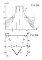
On peut également réaliser la synthèse d'un lobe élargi par les seuls déphaseurs en conservant la même loi équi-amplitude en émission (amplificateur HPA à même puissance de sortie) et la loi de pondération trouvée en réception (quantifiée selon figure 8). Par exemple on ajoute une loi de phase de type parabolique si la mission nécessite un lobe élargi (par exemple en mode SLAR ou "Side looking Airborne Radar", servant à imager le sol en générant des pixels de luminosité proportionnelle à l'intensité de l'écho reçu de chaque cellule de révolution, ou SAR) si l'on veut garder une fauchée au sol constante. Les diagrammes correspondant sont présentés sur les figurés 14, 15 et 16 : ce sont respectivement des diagrammes réception, émission, émission/réception. Avec 128 sources omnidirectionnelles distantes de 0,57 λ on obtient un rendement d'illumination global de -4,83 dB.It is also possible to synthesize an enlarged lobe by the phase shifters alone while keeping the same equi-amplitude law in transmission (HPA amplifier with same output power) and the weighting law found in reception (quantified according to FIG. 8). For example, we add a phase law of the parabolic type if the mission requires an enlarged lobe (for example in SLAR or "Side looking Airborne Radar" mode, used to image the ground by generating pixels of brightness proportional to the intensity of the echo received from each revolution cell, or SAR) if you want to keep a constant swath on the ground. The corresponding diagrams are presented in FIGS. 14, 15 and 16: they are reception, emission, emission / reception diagrams respectively. With 128 omni-directional sources 0.57 λ apart, an overall illumination efficiency of -4.83 dB is obtained.
Ce procédé limite le nombre de commandes à transmettre aux modules actifs à la seule reconfiguration des déphaseurs : celle-ci est de toute façon nécessaire pour le dépointage du faisceau, lié en général à son élargissement. La phase d'élargissement étant identique en émission et en réception, le rythme de commande des déphaseurs est modéré.This process limits the number of commands to be transmitted to the active modules to the only reconfiguration of the phase shifters: this is in any case necessary for the depointing of the beam, generally linked to its widening. Since the enlargement phase is identical in transmission and reception, the control phase of the phase shifters is moderate.
Les atténuateurs situés sur la voie réception des modules actifs (ou les amplificateurs LNA à gain variable) n'ont pas besoin d'être commandés. Ils sont préréglés à la valeur voulue, on ne risque pas ainsi d'ajouter de perturbation de phase.The attenuators located on the reception path of active modules (or LNA amplifiers with variable gain) do not need to be controlled. They are preset to the desired value, there is no risk of adding phase disturbance.
Si l'on veut obtenir des diagrammes élargis mieux formés, on peut s'accorder un degré de liberté supplémentaire consistant à contrôler le gain des modules MAER en réception au cours du temps. Cela permet de mieux adapter la loi d'illumination réception en amplitude et en phase, à chaque largeur de lobe visée.If we want to obtain better-formed enlarged diagrams, we can allow ourselves an additional degree of freedom consisting in controlling the gain of the MAER modules in reception over time. This makes it possible to better adapt the reception illumination law in amplitude and in phase, to each width of the target lobe.
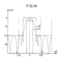
Ainsi les figures 17 à 19 et 20 à 22, qui représentent successivement des diagrammes émission, réception et émission/réception présentent deux lobes de largeur très différentes (1°4 et 8°8 à 3 dB du maximum) générés par le même réseau actif de 48 sources distantes de 0,822 λ .
- les illuminations en émission sont toujours équi-amplitude pour faire fonctionner les amplificateurs HPA à niveau identique.
- par contre le changement de loi d'illumination en réception, en amplitude et en phase, permet de générer soit un lobe très fin de SLL -20 dB (figure 19), soit un lobe large à flancs très raides et de SLL voisin (figure 22).

- the illuminations in emission are always equi-amplitude to operate the HPA amplifiers at identical level.
- on the other hand, the change in illumination law in reception, in amplitude and in phase, makes it possible to generate either a very fine lobe of SLL -20 dB (Figure 19), a wide lobe with very steep sides and a neighboring SLL (Figure 22).
Grâce au degré de contrôle supplémentaire (amplitude en réception), le diagramme du lobe élargi a des flancs plus raides que ceux de la figure 16, le pouvoir discriminateur du radar est donc meilleur.Thanks to the additional degree of control (amplitude on reception), the diagram of the enlarged lobe has steeper sides than those of FIG. 16, the discriminating power of the radar is therefore better.
Le seul inconvénient de cette variante est qu'il faut faire varier au cours du temps le gain de la chaîne réception des modules MAER. Cela augmente le débit des commandes et oblige à prévoir des drivers supplémentaires dans les modules MAER.The only drawback of this variant is that it is necessary to vary over time the gain of the reception chain of the MAER modules. This increases the throughput of commands and requires the provision of additional drivers in the MAER modules.
Deux options sont possibles sur le contrôle de gain :
- ou bien on s'impose une dynamique maximale (6,5 dB pour l'exemple présenté) qui évite d'induire un changement de phase d'insertion de la voie réception du module MAER.
- ou bien, si une dynamique plus importante s'avère nécessaire pour mieux former le diagramme, on calibre les variations de phase induites, et l'on en tient compte dans la commande des déphaseurs. Ceci présente l'inconvénient d'avoir à les reconfigurer à un rythme élevé entre l'émission et la réception.
- or else a maximum dynamic is imposed (6.5 dB for the example presented) which avoids inducing a change of phase of insertion of the reception channel of the MAER module.
- or, if a greater dynamic is necessary to better form the diagram, the induced phase variations are calibrated and taken into account in the control of the phase shifters. This has the disadvantage of having to reconfigure them at a high rate between transmission and reception.
Certains radars n'ont besoin du balayage électronique que dans un plan, par exemple le plan d'élévation dans les modes SCAR (Side-looking airbonne radar) ou SAR.Some radars only require electronic scanning in one plane, for example the elevation plane in SCAR (Side-looking airbonne radar) or SAR modes.
Dans le plan horizontal de l'antenne, on n'a pas besoin de nombreux contrôles d'amplitude et de phase. Pour simplifier l'antenne, on répartit un petit nombre de modules actifs sur la longueur.In the horizontal plane of the antenna, there is no need for many amplitude and phase controls. To simplify the antenna, a small number of active modules are distributed along the length.
Dans ce cas, on ne dispose pas d'assez de contrôles d'amplitude et de phase pour appliquer le procédé précédent à la synthèse du diagramme en azimut. Mais l'espacement plus grand des modules MAER permet d'appliquer un principe différent :
- on réalise cette fois un diagramme azimut identique en émission et en réception ;
- on répartit les modules MAER de façon non régulière sur la longueur d'antenne, pour réaliser la pondération d'amplitude nécessaire avec des amplificateurs HPA fonctionnant tous à même puissance de sortie, afin d'optimiser leur rendement comme dans la version de base.
- this time an identical azimuth diagram is produced in transmission and in reception;
- the MAER modules are distributed in an irregular manner over the antenna length, to achieve the necessary amplitude weighting with HPA amplifiers all operating at the same output power, in order to optimize their performance as in the basic version.
Un exemple de principe ci-dessus est présenté ci-après.An example of the principle above is presented below.
La figure 23 représente une grande antenne active (8m32 x 1m91) destinée à un radar spatial d'observation fonctionnant suivant le mode SAR. Pour pouvoir être repliée sous la coiffe du lanceur, l'antenne est décomposée en trois panneaux 25, 26 et 27. Elle comporte 88 lignes horizontales 28 identiques, comme représentée à la figure 24.FIG. 23 represents a large active antenna (8m32 x 1m91) intended for a space observation radar operating in SAR mode. In order to be foldable under the launcher cap, the antenna is broken down into three
Sur chaque ligne horizontale 28 d'éléments rayonnants (ici des guides à fentes superposés 32 et 33, rayonnant les uns en polarisation horizontale, les autres en polarisation verticale) sont disposés cinq modules MAER 29. Leur répartition non uniforme (plus rapprochés au centre) alliée à un réglage des conductances des fentes rayonnantes pour obtenir une loi d'amplitude variant linéairement en dB d'un bout à l'autre, permet de réaliser un diagramme de bonne qualité (figure 25).Five
En même temps on n'a besoin que de deux types de guides rayonnants :
- des guides 30 de longueur 60,4 cm à loi d'illumination "en biseau" ;
- des guides 31 de longueur 53,7 cm à loi d'illumination uniforme. Ceci simplifie grandement l'industrialisation de cette antenne. Pour le diagramme élévation, on applique par contre le procédé exposé précédemment.
- guides 30 of length 60.4 cm with law of illumination "beveled";
- guides 31 of length 53.7 cm with uniform illumination law. This greatly simplifies the industrialization of this antenna. For the elevation diagram, however, the method described above is applied.
Le balayage électronique étant important dans ce plan on a un contrôle de phase pour chaque sous-panneau (jeu de deux guides 32 et 33 rayonnants en polarisation H et V), c'est-à-dire à un pas voisin de 0,7 fois la longueur d'onde :
- on a donc 88 modules actifs sur la hauteur d'antenne répartis uniformément, la hauteur des guides rayonnants étant toujours la même.
- à l'émission, tous les amplificateurs HPA ayant la même puissance de sortie, on réalise une illumination uniforme comme représenté sur la figure 26,
- à la réception, on règle les atténuateurs situés derrière les amplificateurs LNA pour réaliser la pondération et on obtient le diagramme représenté sur la figure 27 ;
- le diagramme équivalent émission réception représenté sur la figure 28 présente les mêmes qualités déjà décrites.
- there are therefore 88 active modules on the antenna height distributed uniformly, the height of the radiating guides being always the same.
- on transmission, all the HPA amplifiers having the same output power, uniform illumination is carried out as shown in FIG. 26,
- on reception, the attenuators located behind the LNA amplifiers are adjusted to carry out the weighting and the diagram shown in FIG. 27 is obtained;
- the equivalent emission reception diagram shown in FIG. 28 has the same qualities already described.
Il est bien entendu que la présente invention n'a été décrite et représentée qu'à titre d'exemple préférentiel et que l'on pourra remplacer ses éléments constitutifs par des éléments équivalents sans, pour autant, sortir du cadre de l'invention.It is understood that the present invention has only been described and shown as a preferred example and that its constituent elements can be replaced by equivalent elements without, however, departing from the scope of the invention.
Claims (10)
Applications Claiming Priority (2)
| Application Number | Priority Date | Filing Date | Title |
|---|---|---|---|
| FR9003028 | 1990-03-09 | ||
| FR9003028A FR2659500B1 (en) | 1990-03-09 | 1990-03-09 | METHOD OF FORMING THE DIAGRAM OF A HIGH EFFICIENCY ACTIVE ANTENNA FOR ELECTRONICALLY SCANNED RADAR AND ANTENNA USING THE SAME. |
Publications (3)
| Publication Number | Publication Date |
|---|---|
| EP0451497A1 true EP0451497A1 (en) | 1991-10-16 |
| EP0451497B1 EP0451497B1 (en) | 1995-12-20 |
| EP0451497B2 EP0451497B2 (en) | 2000-12-20 |
Family
ID=9394571
Family Applications (1)
| Application Number | Title | Priority Date | Filing Date |
|---|---|---|---|
| EP91103216A Expired - Lifetime EP0451497B2 (en) | 1990-03-09 | 1991-03-04 | Method for forming the radiation pattern of an active antenna for radar with electronic scanning, and antenna using this method |
Country Status (7)
| Country | Link |
|---|---|
| US (1) | US5124712A (en) |
| EP (1) | EP0451497B2 (en) |
| JP (1) | JP2765770B2 (en) |
| CA (1) | CA2037849C (en) |
| DE (1) | DE69115544T3 (en) |
| ES (1) | ES2081379T3 (en) |
| FR (1) | FR2659500B1 (en) |
Cited By (2)
| Publication number | Priority date | Publication date | Assignee | Title |
|---|---|---|---|---|
| JPH05107335A (en) * | 1991-10-19 | 1993-04-27 | Nec Corp | Active phased array radar aerial device |
| FR2943182A1 (en) * | 2009-03-10 | 2010-09-17 | Thales Sa | Method for adjusting lobe of radiation pattern of plane radar antenna in airborne vehicle i.e. airplane, involves selecting sign of value of maximum phase at ends of antenna according to desired distribution of radiated energy |
Families Citing this family (14)
| Publication number | Priority date | Publication date | Assignee | Title |
|---|---|---|---|---|
| FR2679704B1 (en) * | 1991-07-26 | 1993-09-24 | Alcatel Espace | NETWORK ANTENNA FOR MICROWAVE WAVES. |
| JP2560001Y2 (en) * | 1991-09-04 | 1998-01-21 | 三菱電機株式会社 | Transmission / reception module |
| JP2006512691A (en) | 2002-10-22 | 2006-04-13 | アイシス テクノロジーズ | Non-peripheral processing control module with improved heat dissipation characteristics |
| EP1557074A4 (en) | 2002-10-22 | 2010-01-13 | Sullivan Jason | Robust customizable computer processing system |
| KR101499826B1 (en) | 2002-10-22 | 2015-03-10 | 제이슨 에이. 설리반 | Robust customizable computing system, processing control unit, and wireless computing network apparatus |
| GB0526661D0 (en) | 2005-11-23 | 2006-12-13 | Bae Systems Plc | Array Antenna |
| JP5040549B2 (en) * | 2007-09-20 | 2012-10-03 | 日本電気株式会社 | Synthetic aperture radar, compact polarimetry SAR processing method, program |
| US9653799B2 (en) * | 2010-11-16 | 2017-05-16 | Raytheon Company | Method and apparatus for controlling sidelobes of an active antenna array |
| WO2012109393A1 (en) | 2011-02-08 | 2012-08-16 | Henry Cooper | High gain frequency step horn antenna |
| US9478868B2 (en) | 2011-02-09 | 2016-10-25 | Xi3 | Corrugated horn antenna with enhanced frequency range |
| EP2883081B1 (en) * | 2012-08-09 | 2017-10-25 | Israel Aerospace Industries Ltd. | Friend or foe identification system and method |
| WO2014043401A1 (en) * | 2012-09-12 | 2014-03-20 | Wireless Research Development | Wireless antenna communicating system and method |
| US9450309B2 (en) | 2013-05-30 | 2016-09-20 | Xi3 | Lobe antenna |
| US11754706B2 (en) * | 2020-09-17 | 2023-09-12 | Rockwell Collins, Inc. | Agile antenna taper based on weather radar feedback |
Citations (6)
| Publication number | Priority date | Publication date | Assignee | Title |
|---|---|---|---|---|
| US4052723A (en) * | 1976-04-26 | 1977-10-04 | Westinghouse Electric Corporation | Randomly agglomerated subarrays for phased array radars |
| DE2943359A1 (en) † | 1978-11-03 | 1980-05-14 | The Bendix Corp., Southfield, Mich. | METHOD AND DEVICE FOR OPERATING A PHASE-CONTROLLED ANTENNA |
| EP0194244A1 (en) * | 1985-03-08 | 1986-09-10 | Telefonaktiebolaget L M Ericsson | Test apparatus in a radar system |
| EP0246640A2 (en) * | 1986-05-23 | 1987-11-25 | Ball Corporation | Transmit/receive module for phased array antenna system |
| EP0275303A1 (en) † | 1986-07-29 | 1988-07-27 | Hughes Aircraft Co | Low sidelobe solid state phased array antenna apparatus. |
| US4791421A (en) * | 1986-09-10 | 1988-12-13 | Westinghouse Electric Corp. | Transmit-receive module for phased-array antennas |
Family Cites Families (8)
| Publication number | Priority date | Publication date | Assignee | Title |
|---|---|---|---|---|
| JPS58100503A (en) * | 1981-12-09 | 1983-06-15 | Mitsubishi Electric Corp | Radar device |
| JPS596784U (en) * | 1982-07-05 | 1984-01-17 | 三菱電機株式会社 | Active transmit/receive module |
| US4766437A (en) * | 1983-01-12 | 1988-08-23 | Grumman Aerospace Corporation | Antenna apparatus having means for changing the antenna radiation pattern |
| JPS59157347U (en) * | 1983-04-08 | 1984-10-22 | 三菱電機株式会社 | Transmitting/receiving device |
| JPS6150278U (en) * | 1984-09-05 | 1986-04-04 | ||
| JPS63175788A (en) * | 1987-01-16 | 1988-07-20 | Mitsubishi Heavy Ind Ltd | Beam multi-division phased array radar |
| JP2589811B2 (en) | 1989-06-30 | 1997-03-12 | 松下電器産業株式会社 | Receiver |
| US5017928A (en) * | 1990-08-22 | 1991-05-21 | The United States Of America As Represented By The Secretary Of The Air Force | Low sidelobe array by amplitude edge tapering the edge elements |
-
1990
- 1990-03-09 FR FR9003028A patent/FR2659500B1/en not_active Expired - Fee Related
-
1991
- 1991-03-04 ES ES91103216T patent/ES2081379T3/en not_active Expired - Lifetime
- 1991-03-04 DE DE69115544T patent/DE69115544T3/en not_active Expired - Lifetime
- 1991-03-04 EP EP91103216A patent/EP0451497B2/en not_active Expired - Lifetime
- 1991-03-06 US US07/665,202 patent/US5124712A/en not_active Expired - Lifetime
- 1991-03-08 JP JP3125606A patent/JP2765770B2/en not_active Expired - Lifetime
- 1991-03-08 CA CA002037849A patent/CA2037849C/en not_active Expired - Lifetime
Patent Citations (6)
| Publication number | Priority date | Publication date | Assignee | Title |
|---|---|---|---|---|
| US4052723A (en) * | 1976-04-26 | 1977-10-04 | Westinghouse Electric Corporation | Randomly agglomerated subarrays for phased array radars |
| DE2943359A1 (en) † | 1978-11-03 | 1980-05-14 | The Bendix Corp., Southfield, Mich. | METHOD AND DEVICE FOR OPERATING A PHASE-CONTROLLED ANTENNA |
| EP0194244A1 (en) * | 1985-03-08 | 1986-09-10 | Telefonaktiebolaget L M Ericsson | Test apparatus in a radar system |
| EP0246640A2 (en) * | 1986-05-23 | 1987-11-25 | Ball Corporation | Transmit/receive module for phased array antenna system |
| EP0275303A1 (en) † | 1986-07-29 | 1988-07-27 | Hughes Aircraft Co | Low sidelobe solid state phased array antenna apparatus. |
| US4791421A (en) * | 1986-09-10 | 1988-12-13 | Westinghouse Electric Corp. | Transmit-receive module for phased-array antennas |
Non-Patent Citations (22)
| Title |
|---|
| D.N. McQuiddy,Jr.: " Solid State Radar's path to GaAs"; dans:1982 IEEE MTT-S Digest, 15 à 17 Juin 1982,Dallas, Texas, p.176 à 178 † |
| Dodson: " L Band Solid State Array Radar Overview ";dans:Eli Brookner: " Radar Technology" ( Artech House,Inc., 1988,Norwood,Mass.),chap.19,pages 265 à 273 † |
| E.H.Gregory: " Applicability,Availability and Affordability of GaAs MMICs in Military Systems ";Microwave Journal, Mars 1987,pages 119 à 126 † |
| Eli Brookner: " Array Radars: An Update, PartI and II"; Microwave Journal,Fevrier 1987,pages 117 à 138, und Microwave Journal,Mars 1987,pages 167 à 174 † |
| H.Moschüring: "Sende/Empfangsmodul für künftige aktive phasenwinkel- und amplitudengesteuerte RADAR Antennensysteme ";dans: 7.Radarsymposium, 10 à 12 Octobre 1989, Ulm;éditeur:Deutsche Gesellschaft für Ortung und Navigation e.V.,(Verlag TüV Rheinland GmbH,Köln,1989),pages 365 à 375. † |
| Harwell: " Airborne Solid State Radar Technology ", dans : Eli Brookner : " Radar Technology " ( Artech House, Inc., 1988, Norwood, Mass.), chap.20,pages 276 à 287 † |
| IEEE Transactions on antennas and propagation, Vol. AP-29,no 1,1981, Microstrip Array Technology, Robert J. Mailloux et al † |
| J.J.Lee: " Sidelobes Control of Solid-State Array Antennas "; IEEE Transactions on Antennas and Propagation, Vol.36,No.3,Mars 1988,pages 339 à 344 † |
| K.Solbach:" Radar auf dem Weg zum Active Array";dans:7.Radarsymposium,10 à 12 Octobre 1989, ULM;éditeur:Deutsche Gesellschaft für Ortung und Navigation e.V (Verlag TüV Rheinland GmbH,Köln,1989),pages 347 à 351 † |
| L'Onde Electrique, Mars-Avril 1989, Vol.69, No. 2,pages 7-14, Avenir des antennes-réseaux actives,Jean-Louis Pourailly et Claude Guerin † |
| M.Cohn,B.Sichelstiel: " Antenna and Monolithic MIC T/R Module Architecture for an Advanced Airborne Fire Control Radar System"; dans: Proceedings of the EASCON-Conf. 1981 (IEEE-Publication), pages 179 à 183 † |
| M.E.Davis,J.K.Smith,C.E.Grove: " L-Band T/R Module for Airborne Phased Array "; Microwave Journal, Fevrier 1977,pages 54 à 60. † |
| Modern Radar System Analysis, David K.Barton, Artech House, Inc. 1988 † |
| N.Amitay,C.P.Wu,V.Galindo:" Methods of Phased Array Analysis";dans:A.A.Oliner,G.H.Knittel: " Phased Array Antennas "; (Artech House Inc., 1972,Dedham,Mass.),pages 68,69 † |
| Present and Future Trends in Radar Systems and components : dans: Eli Brookner: " Radar Technology " ( Artech House Inc., 1988, Norwood, Mass.), pages 325 à 287 † |
| Proceedings of the IEEE,vol.56,no 11,1968,Design of Electronic Scanning Radar Systems,Peter J.Kahrilas † |
| Proceedings of the IEEE,vol.70,no 3,1982,Phased Array Theory and Technology, Robert J.Mailloux † |
| R.J.Naster,M.R.Lang: " Affordable MMIC Designs for Phased Arrays "; Microwave Journal,Mars 1987,pages 141 à 150 † |
| Radar Handbook, Merill I Skolnik, 1970 † |
| T.C.Cheston,J.Frank: Array Antennas";dans:M.I.Skolnik: " Radar Handbook ",( McGraw-Hill; 1970,New York ), chapitre 11,pages 11-24 et 11-25 † |
| U.Petri: " Kompensation von Amplitudenbelegungsfehlern bei Gruppenantennen durch Phasen-Einstellung ";Wiss.Ber.AEG-TELEFUNKEN 54(1981) 1-2,p.58 à 63 † |
| W.R.Wisseman, L.C.Witkowski, G.E.Brehm,R.P.Coats,D.D. Heston, R.D. Hudgens,R.E.Lehmann,H.M.Macksey and H.Q. Tserng: " X-Band GaAs Single-Chip T/R Radar Module"; Microwave Journal, Septembre 1987, pages 167 à 173 † |
Cited By (2)
| Publication number | Priority date | Publication date | Assignee | Title |
|---|---|---|---|---|
| JPH05107335A (en) * | 1991-10-19 | 1993-04-27 | Nec Corp | Active phased array radar aerial device |
| FR2943182A1 (en) * | 2009-03-10 | 2010-09-17 | Thales Sa | Method for adjusting lobe of radiation pattern of plane radar antenna in airborne vehicle i.e. airplane, involves selecting sign of value of maximum phase at ends of antenna according to desired distribution of radiated energy |
Also Published As
| Publication number | Publication date |
|---|---|
| DE69115544T2 (en) | 1996-05-02 |
| EP0451497B1 (en) | 1995-12-20 |
| US5124712A (en) | 1992-06-23 |
| FR2659500B1 (en) | 1992-05-15 |
| FR2659500A1 (en) | 1991-09-13 |
| JP2765770B2 (en) | 1998-06-18 |
| DE69115544T3 (en) | 2001-08-09 |
| ES2081379T3 (en) | 1996-03-01 |
| EP0451497B2 (en) | 2000-12-20 |
| CA2037849A1 (en) | 1991-09-10 |
| CA2037849C (en) | 1994-09-20 |
| DE69115544D1 (en) | 1996-02-01 |
| JPH04230881A (en) | 1992-08-19 |
Similar Documents
| Publication | Publication Date | Title |
|---|---|---|
| EP0451497B1 (en) | Method for forming the radiation pattern of an active antenna for radar with electronic scanning, and antenna using this method | |
| CA2037841C (en) | High efficiency active printed antenna system for an agile space radar | |
| EP2532050B1 (en) | On-board directional flat-plate antenna, vehicle comprising such an antenna, and satellite telecommunication system comprising such a vehicle | |
| EP2532046B1 (en) | Flat-plate scanning antenna for land mobile application, vehicle comprising such an antenna, and satellite telecommunication system comprising such a vehicle | |
| CA2110634C (en) | Variable polarization synthesis active antenna | |
| FR2939568A1 (en) | SOURCE-SHARING ANTENNA AND METHOD FOR PROVIDING SOURCE-SHARED ANTENNA FOR MULTI-BEAM MAKING | |
| EP3577720B1 (en) | Elementary antenna comprising a planar radiating device | |
| EP0288988B1 (en) | Adaptive antenna system for high frequencies, especially for ultra-high frequencies | |
| EP3176875B1 (en) | Active antenna architecture with reconfigurable hybrid beam formation | |
| EP1533866B1 (en) | Adaptive phased array antenna with digital beam forming | |
| EP1188202B1 (en) | Device for transmitting and/or receiving signals | |
| EP1351333A2 (en) | Adaptive phased array antenna and radar using the same | |
| EP1107359A1 (en) | Radiating source for an antenna to be installed in a satellite | |
| EP4020834A1 (en) | Device for controlling an active antenna with scanning | |
| FR2717312A1 (en) | Directional directional transmitter. | |
| CA2026129A1 (en) | Two-gate field effect transistor attenuator | |
| FR2930844A1 (en) | Active electronically scanned array aerial for airborne radar application, has supply line that is prolongation of printed circuit line of transmission and reception module and contained in plane perpendicular to plane of radiating element | |
| FR2828583A1 (en) | Regulation/closure electronic sweep antenna has phase shifter with phase shift cell having cascaded switches and rear cells carrying radiating element/switches pass state switch providing antenna closure | |
| EP3155689A1 (en) | Flat antenna for satellite communication | |
| Forrest | Un aperçu des possibilités d’évolution des antennes futures | |
| FR2723264A1 (en) | Radar aerial array with good directivity e.g. for guided missile | |
| EP3521851A1 (en) | Device and method for transmitting/receiving radio signals | |
| FR2734410A1 (en) | Microwave frequency antenna for radar jamming suppression | |
| BE425367A (en) |
Legal Events
| Date | Code | Title | Description |
|---|---|---|---|
| PUAI | Public reference made under article 153(3) epc to a published international application that has entered the european phase |
Free format text: ORIGINAL CODE: 0009012 |
|
| AK | Designated contracting states |
Kind code of ref document: A1 Designated state(s): DE ES FR GB IT SE |
|
| 17P | Request for examination filed |
Effective date: 19920330 |
|
| 17Q | First examination report despatched |
Effective date: 19940218 |
|
| GRAA | (expected) grant |
Free format text: ORIGINAL CODE: 0009210 |
|
| AK | Designated contracting states |
Kind code of ref document: B1 Designated state(s): DE ES FR GB IT SE |
|
| REF | Corresponds to: |
Ref document number: 69115544 Country of ref document: DE Date of ref document: 19960201 |
|
| ITF | It: translation for a ep patent filed |
Owner name: JACOBACCI & PERANI S.P.A. |
|
| REG | Reference to a national code |
Ref country code: ES Ref legal event code: FG2A Ref document number: 2081379 Country of ref document: ES Kind code of ref document: T3 |
|
| GBT | Gb: translation of ep patent filed (gb section 77(6)(a)/1977) |
Effective date: 19960314 |
|
| PLBQ | Unpublished change to opponent data |
Free format text: ORIGINAL CODE: EPIDOS OPPO |
|
| PLBI | Opposition filed |
Free format text: ORIGINAL CODE: 0009260 |
|
| PLBF | Reply of patent proprietor to notice(s) of opposition |
Free format text: ORIGINAL CODE: EPIDOS OBSO |
|
| 26 | Opposition filed |
Opponent name: DAIMLER-BENZ AEROSPACE AG SENSORSYSTEME Effective date: 19960920 Opponent name: HOLLANDSE SIGNAALAPPARATEN B.V. Effective date: 19960912 |
|
| PLBF | Reply of patent proprietor to notice(s) of opposition |
Free format text: ORIGINAL CODE: EPIDOS OBSO |
|
| PLBF | Reply of patent proprietor to notice(s) of opposition |
Free format text: ORIGINAL CODE: EPIDOS OBSO |
|
| RAP2 | Party data changed (patent owner data changed or rights of a patent transferred) |
Owner name: ALCATEL SPACE INDUSTRIES |
|
| PLAW | Interlocutory decision in opposition |
Free format text: ORIGINAL CODE: EPIDOS IDOP |
|
| PLAW | Interlocutory decision in opposition |
Free format text: ORIGINAL CODE: EPIDOS IDOP |
|
| PUAH | Patent maintained in amended form |
Free format text: ORIGINAL CODE: 0009272 |
|
| STAA | Information on the status of an ep patent application or granted ep patent |
Free format text: STATUS: PATENT MAINTAINED AS AMENDED |
|
| 27A | Patent maintained in amended form |
Effective date: 20001220 |
|
| AK | Designated contracting states |
Kind code of ref document: B2 Designated state(s): DE ES FR GB IT SE |
|
| PGFP | Annual fee paid to national office [announced via postgrant information from national office to epo] |
Ref country code: SE Payment date: 20010305 Year of fee payment: 11 |
|
| PGFP | Annual fee paid to national office [announced via postgrant information from national office to epo] |
Ref country code: ES Payment date: 20010316 Year of fee payment: 11 |
|
| ITF | It: translation for a ep patent filed |
Owner name: JACOBACCI & PERANI S.P.A. |
|
| GBTA | Gb: translation of amended ep patent filed (gb section 77(6)(b)/1977) | ||
| PG25 | Lapsed in a contracting state [announced via postgrant information from national office to epo] |
Ref country code: ES Free format text: LAPSE BECAUSE OF FAILURE TO SUBMIT A TRANSLATION OF THE DESCRIPTION OR TO PAY THE FEE WITHIN THE PRESCRIBED TIME-LIMIT Effective date: 20010520 |
|
| REG | Reference to a national code |
Ref country code: GB Ref legal event code: IF02 |
|
| PG25 | Lapsed in a contracting state [announced via postgrant information from national office to epo] |
Ref country code: SE Free format text: THE PATENT HAS BEEN ANNULLED BY A DECISION OF A NATIONAL AUTHORITY Effective date: 20020330 |
|
| PLAB | Opposition data, opponent's data or that of the opponent's representative modified |
Free format text: ORIGINAL CODE: 0009299OPPO |
|
| PGFP | Annual fee paid to national office [announced via postgrant information from national office to epo] |
Ref country code: FR Payment date: 20100324 Year of fee payment: 20 Ref country code: IT Payment date: 20100313 Year of fee payment: 20 |
|
| PGFP | Annual fee paid to national office [announced via postgrant information from national office to epo] |
Ref country code: GB Payment date: 20100303 Year of fee payment: 20 |
|
| PGFP | Annual fee paid to national office [announced via postgrant information from national office to epo] |
Ref country code: DE Payment date: 20100312 Year of fee payment: 20 |
|
| REG | Reference to a national code |
Ref country code: DE Ref legal event code: R071 Ref document number: 69115544 Country of ref document: DE |
|
| REG | Reference to a national code |
Ref country code: GB Ref legal event code: PE20 Expiry date: 20110303 |
|
| PG25 | Lapsed in a contracting state [announced via postgrant information from national office to epo] |
Ref country code: GB Free format text: LAPSE BECAUSE OF EXPIRATION OF PROTECTION Effective date: 20110303 |
|
| PG25 | Lapsed in a contracting state [announced via postgrant information from national office to epo] |
Ref country code: DE Free format text: LAPSE BECAUSE OF EXPIRATION OF PROTECTION Effective date: 20110304 |