EP0451335A1 - Strike-hammer driving device - Google Patents
Strike-hammer driving device Download PDFInfo
- Publication number
- EP0451335A1 EP0451335A1 EP90122014A EP90122014A EP0451335A1 EP 0451335 A1 EP0451335 A1 EP 0451335A1 EP 90122014 A EP90122014 A EP 90122014A EP 90122014 A EP90122014 A EP 90122014A EP 0451335 A1 EP0451335 A1 EP 0451335A1
- Authority
- EP
- European Patent Office
- Prior art keywords
- stop
- lever
- adjusting
- axis
- gong
- Prior art date
- Legal status (The legal status is an assumption and is not a legal conclusion. Google has not performed a legal analysis and makes no representation as to the accuracy of the status listed.)
- Withdrawn
Links
Images

Classifications
-
- G—PHYSICS
- G04—HOROLOGY
- G04B—MECHANICALLY-DRIVEN CLOCKS OR WATCHES; MECHANICAL PARTS OF CLOCKS OR WATCHES IN GENERAL; TIME PIECES USING THE POSITION OF THE SUN, MOON OR STARS
- G04B21/00—Indicating the time by acoustic means
- G04B21/02—Regular striking mechanisms giving the full hour, half hour or quarter hour
- G04B21/06—Details of striking mechanisms, e.g. hammer, fan governor
-
- G—PHYSICS
- G04—HOROLOGY
- G04B—MECHANICALLY-DRIVEN CLOCKS OR WATCHES; MECHANICAL PARTS OF CLOCKS OR WATCHES IN GENERAL; TIME PIECES USING THE POSITION OF THE SUN, MOON OR STARS
- G04B21/00—Indicating the time by acoustic means
- G04B21/02—Regular striking mechanisms giving the full hour, half hour or quarter hour
- G04B21/12—Reiterating watches or clocks
Definitions
- the invention relates to a stop device for a gong spring of a watch, in particular a repeater watch, with a gong spring arranged on a circuit board, against which one end provided with a stop hammer of a stop lever which can be pivoted about a pivot axis can be moved, with an end stop acting on the stop lever an axis between a basic position and a clamping position of the intermediate lever, which can be pivotably attacked, by means of which the stop lever can be moved against a spring force from a basic position in which the stop hammer is at a short distance from the gong to a clamping position remote from the gong, with an adjustable elastic stop on which the The stop lever in the basic position or the intermediate lever in the basic position is in contact and by means of which the distance of the stop hammer from the gong can be determined in the basic position.
- the stop lever is moved from the tensioned position with current into the basic position by a spring force.
- the swing must be large to deform the elastic stop so far that the hammer can hit the tonearm.
- this requires a relatively small distance between the stop hammer and the gong.
- this distance must not be too small either, since otherwise the gong spring, which is set in vibration by the striking stop hammer, comes into contact with the striking hammer, which is moved back somewhat by the elastically deforming stop, and the vibrations of the gong spring are thereby damped.
- the elastic stop is adjustable.
- the object of the invention is therefore to design a stop device of the type mentioned in such a way that its stop is adjustable in a simple and easy manner ensuring an optimal sound of the gong spring.
- the stop is arranged in an adjustment lever pivotally adjustable about an axis, which is supported on an arranged on the board at a distance from the axis, rotatable about an eccentric axis of rotation and engaging in a recess of the adjusting lever.
- the elastic stop can be a spring arm and form the stop surface at its free end.
- the eccentric has a circular adjusting head with an axis eccentric to the axis of rotation, which engages in a groove formed approximately radially to the axis of the adjusting lever in the adjusting lever, the width of which corresponds approximately to the diameter of the adjusting head.
- the eccentric preferably has a mounting pin which forms the axis of rotation and which can be press-fitted into a hole in the board.
- the adjusting head can have a screw slot on its end face facing away from the mounting pin.
- the adjusting lever can be locked against rotation in its setting position. This is possible on the one hand because the adjusting lever has a threaded hole, in which a set screw can be arranged, which can be supported with the free end of its shaft on the board.
- a further embodiment consists in that the adjusting lever has a bore through which an adjusting screw of smaller diameter can be passed and screwed into a threaded hole in the board, the head of the adjusting screw being able to be supported on the adjusting lever.
- the adjusting lever can be formed in one piece with a tension spring arm, through the free end of which the stop lever is urged into the tension position remote from the spring.
- the stop device shown is arranged on a circuit board 1 and has a gong spring 2 with a tonearm 3 fastened on the circuit board 1.
- a with one end pivotable about an axis 4 on the board 1 stop 5 has its other free end a stop hammer 6, which is in the basic position shown a short distance from the tonearm 3.
- a clamping arm 7 is firmly connected to the stop lever 5.
- the scoop 12 bears against the arm 11 via a projecting drive pin 13.
- the intermediate lever 9 is also pivoted via the drive pin 13 .
- the arm 10, which engages on the tension arm 7, moves the stop lever 5 counterclockwise from its illustrated basic position into a tension position until the engaging tooth 14 slips over the tip of the mandrel 16 and releases the creator 12.
- tension spring arm 17 is tensioned during this movement and moves after release of the scoop 12 through the tooth 14 the tension arm and thus the stop lever 5 and Hammer 6 back with a swing towards the basic position.
- the intermediate lever 9 rests with its arm 10 to an elastic stop 18, which thereby determines the distance between the tonearm 3 and the stop hammer 6.
- the stop 18 designed as a spring arm is elastically deformed to such an extent that the distance between the tonearm 3 and the stop hammer 6 is overcome and the stop hammer 6 strikes the tonearm 3. This causes it to vibrate and produces a sound.
- the elasticity of the stop 18 then immediately moves the stop lever 5 and thus the stop hammer 6 away from the tonearm 3 so that it can swing freely.
- Both the tension spring arm 17 and the stop 18 are integrally formed with an adjusting lever 19.
- the adjusting lever 19 is a two-armed lever which is freely pivotable about an axis 20, one lever arm of which is formed by the stop 18 and the second lever arm of which is on the adjusting arm 21.
- a groove 22 is formed which extends approximately radially to the axis 20, the width of which corresponds approximately to the diameter of an adjusting head 23 of an eccentric 24 guided in the groove 22.
- the eccentric 24 has an assembly pin 25 which projects eccentrically to the axis 20 and which is press-fitted into a bore 26 in the circuit board 1.
- the adjusting head 23 On its side facing away from the mounting pin 25, the adjusting head 23 is provided with a screw slot 27 into which a screwdriver is inserted and the eccentric 24 can be rotated in the bore 26 while overcoming the frictional forces of the mounting pin 25.
- the adjusting lever 19 is pivoted about the axis 20. This also leads to a change in position of the stop 18 and the intermediate lever 9 resting thereon. This correspondingly pivots the stop lever 5 via the tensioning arm 7 and changes the distance between the tonearm 3 and the stop hammer 6.
- the newly adjusted basic position can be secured by an adjusting screw 28 which extends through a fixing hole 29 of larger diameter of the adjusting lever 19 and is screwed with its threaded shaft into a threaded hole 30 on the circuit board 1.
- the head 31 of the adjusting screw 28 comes to bear on the side facing away from the circuit board 1 against the adjusting lever 19 and holds it firmly in this position.
Landscapes
- Physics & Mathematics (AREA)
- General Physics & Mathematics (AREA)
- Portable Nailing Machines And Staplers (AREA)
- Electromechanical Clocks (AREA)
Abstract
Description
Die Erfindung bezieht sich auf eine Anschlagvorrichtung für eine Tonfeder einer Uhr, insbesondere einer Repetieruhr, mit auf einer Platine angeordnet einer Tonfeder, gegen die das eine mit einem Anschlaghammer versehene Ende eines um eine Schwenkachse schwenkbaren Anschlaghebels bewegbar ist, mit einem am Anschlaghebel angreifenden, um eine Achse zwischen einer Grundstellung und einer Spannstellung schwenkbar angreifbaren Zwischenhebel, durch den der Anschlaghebel entgegen einer Federkraft aus einer Grundposition, in der der Anschlaghammer einen geringen Abstand zur Tonfeder aufweist, in eine tonfederferne Spannposition bewegbar ist, mit einem verstellbaren elastischen Anschlag, an dem der Anschlaghebel in der Grundstellung bzw. der Zwischenhebel in der Grundposition in Anlage ist und durch den der Abstand des Anschlaghammers von der Tonfeder in der Grundstellung festlegbar ist.The invention relates to a stop device for a gong spring of a watch, in particular a repeater watch, with a gong spring arranged on a circuit board, against which one end provided with a stop hammer of a stop lever which can be pivoted about a pivot axis can be moved, with an end stop acting on the stop lever an axis between a basic position and a clamping position of the intermediate lever, which can be pivotably attacked, by means of which the stop lever can be moved against a spring force from a basic position in which the stop hammer is at a short distance from the gong to a clamping position remote from the gong, with an adjustable elastic stop on which the The stop lever in the basic position or the intermediate lever in the basic position is in contact and by means of which the distance of the stop hammer from the gong can be determined in the basic position.
Bei derartigen Anschlagvorrichtungen wird der Anschlaghebel aus der Spannstellung durch eine Federkraft mit Strom in die Grundstellung bewegt. Dabei muß der Schwung groß sein, um den elastischen Anschlag so weit zu verformen, daß der Anschlaghammer auf den Tonarm aufschlagen kann. Dies bedingt in der Grundposition einen relativ geringen Abstand des Anschlaghammers zur Tonfeder. Dieser Abstand darf aber auch nicht zu gering sein, da sonst die von dem aufschlagenden Anschlaghammer in Schwingung versetzte Tonfeder mit dem vom elastisch sich zurückverformenden Anschlag etwas zurückbewegten Anschlaghammer in Berührung kommt und dadurch die Schwingungen der Tonfeder gedämpft werden. Um dazu den erforderlichen optimalen Abstand zwischen Tonfeder und Anschlaghammer in dessen Grundposition einstellen zu können, ist der elastische Anschlag verstellbar ausgebildet.With stop devices of this type, the stop lever is moved from the tensioned position with current into the basic position by a spring force. The swing must be large to deform the elastic stop so far that the hammer can hit the tonearm. In the basic position, this requires a relatively small distance between the stop hammer and the gong. However, this distance must not be too small either, since otherwise the gong spring, which is set in vibration by the striking stop hammer, comes into contact with the striking hammer, which is moved back somewhat by the elastically deforming stop, and the vibrations of the gong spring are thereby damped. In order to be able to set the required optimal distance between the gong and the stop hammer in its basic position, the elastic stop is adjustable.
Dazu ist es bekannt, den unter Krafteinwirkung verschiebbar auf der Platine angeordneten Anschlag mittels einer Stellschraube den Abstand zwischen Tonfeder und Anschlaghammer vergrössernd zu verschieben. Erfolgt beim Abstimmvorgang ein zu starkes Verschieben, so müssen alle über der Anschlagvorrichtung angeordneten Bauteile der Uhr entfernt und der Anschlag freigelegt werden, um ein Lösen und Zurückstellen des Anschlags zu ermöglichen.For this purpose, it is known to use a set screw to move the stop, which is displaceably arranged under force on the board, to increase the distance between the gong and the stop hammer. If there is too much movement during the tuning process, all components of the watch arranged above the stop device must be removed and the stop exposed to enable the stop to be released and reset.
Aufgabe der Erfindung ist es daher, eine Anschlagvorrichtung der eingangs genannten Art derart auszubilden, daß deren Anschlag auf einfache und leichte Weise einen optimalen Klang der Tonfeder gewährleistend einstellbar ist.The object of the invention is therefore to design a stop device of the type mentioned in such a way that its stop is adjustable in a simple and easy manner ensuring an optimal sound of the gong spring.
Diese Aufgabe wird erfindungsgemäß dadurch gelöst, daß der Anschlag in einem um eine Achse schwenkbar verstellbaren Justierhebel angeordnet ist, der an einem an der Platine in einem Abstand zur Achse angeordneten, um eine exzentrische Drehachse drehbaren und in eine Ausnehmung des Justierhebels eingreifenden Exzenter abgestützt ist. Diese Ausbildung ermöglicht es, allein durch Verdrehen des Exzenters den Anschlag sowohl in den Abstand zwischen Tonfeder und Anschlaghammer vergrößernder als auch verringernder Richtung feinfühlig zu verstellen.This object is achieved in that the stop is arranged in an adjustment lever pivotally adjustable about an axis, which is supported on an arranged on the board at a distance from the axis, rotatable about an eccentric axis of rotation and engaging in a recess of the adjusting lever. This design makes it possible to adjust the stop both in the distance between the gong and the striking hammer by increasing or decreasing the direction by turning the eccentric.
In einfacher bauteilarmer Ausbildung kann der elastische Anschlag ein Federarm sein und an seinem freien Ende die Anschlagfläche bilden.In a simple design with few components, the elastic stop can be a spring arm and form the stop surface at its free end.
Eine einfache bauteilarme Ausführung besteht darin, daß der Exzenter einen kreisförmigen Stellkopf mit zur Drehachse exzentrischer Achse aufweist, der in eine etwa radial zur Achse des Justierhebels gerichtete im Justierhebel ausgebildete Nut eingreift, deren Breite etwa dem Durchmesser des Stellkopfes entspricht. Dabei weist vorzugsweise der Exzenter einen die Drehachse bildenden Montagezapfen auf, der unter Preßpassung in eine Bohrung der Platine einsetzbar ist.A simple design with few components is that the eccentric has a circular adjusting head with an axis eccentric to the axis of rotation, which engages in a groove formed approximately radially to the axis of the adjusting lever in the adjusting lever, the width of which corresponds approximately to the diameter of the adjusting head. The eccentric preferably has a mounting pin which forms the axis of rotation and which can be press-fitted into a hole in the board.
Zum einfachen Verstellen mittels eines Schraubenziehers kann der Stellkopf an seiner dem Montagezapfen abgewandten Stirnseite einen Schraubschlitz besitzen.For simple adjustment by means of a screwdriver, the adjusting head can have a screw slot on its end face facing away from the mounting pin.
Zur Sicherung der einjustierten Position des Anschlags kann der Justierhebel in seiner Einstellposition verdrehsicherbar sein. Dies ist zum einen dadurch möglich, daß der Justierhebel eine Gewindebohrung aufweist, in der eine Stellschraube anordenbar ist, die mit dem freien Ende ihres Schafts auf der Platine abstützbar ist.To secure the adjusted position of the stop, the adjusting lever can be locked against rotation in its setting position. This is possible on the one hand because the adjusting lever has a threaded hole, in which a set screw can be arranged, which can be supported with the free end of its shaft on the board.
Eine weitere Ausführungsform besteht darin, daß der Justierhebel eine Bohrung aufweist, durch die eine Stellschraube geringeren Durchmessers hindurchführbar und in eine Gewindebohrung der Platine einschraubbar ist, wobei der Kopf der Stellschraube auf dem Justierhebel abstützbar ist.A further embodiment consists in that the adjusting lever has a bore through which an adjusting screw of smaller diameter can be passed and screwed into a threaded hole in the board, the head of the adjusting screw being able to be supported on the adjusting lever.
Zur Reduzierung der Bauteile kann der Justierhebel einteilig mit einem Spannfederarm ausgebildet sein, durch dessen freies Ende der Anschlaghebel in die tonfederferne Spannposition beaufschlagt ist.To reduce the components, the adjusting lever can be formed in one piece with a tension spring arm, through the free end of which the stop lever is urged into the tension position remote from the spring.
Ein Ausführungsbeispiel der Erfindung ist in der Zeichnung dargestellt und wird im folgenden näher beschrieben. Es zeigen
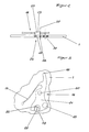
Figur 1- eine Draufsicht einer Anschlagvorrichtung,
Figur 2- eine Seitenansicht des Bereichs des Justierhebels aus
Figur 1, Figur 3- eine Draufsicht des Bereichs des Justierhebels nach
Figur 2.
- Figure 1
- a plan view of a stop device,
- Figure 2
- 2 shows a side view of the area of the adjusting lever from FIG. 1,
- Figure 3
- 3 shows a plan view of the area of the adjusting lever according to FIG. 2.
Die dargestellte Anschlagvorrichtung ist auf einer Platine 1 angeordnet und besitzt eine auf der Platine 1 befestigte Tonfeder 2 mit einem Tonarm 3.The stop device shown is arranged on a
Ein mit seinem einen Ende um eine Achse 4 schwenkbar an der Platine 1 gelagerter Anschlag 5 besitzt an seinem anderen freien Ende einen Anschlaghammer 6, der in der dargestellten Grundposition einen geringen Abstand zum Tonarm 3 besitzt.A with one end pivotable about an
Mit dem Anschlaghebel 5 fest verbunden ist eine Spannarm 7.A clamping arm 7 is firmly connected to the stop lever 5.
Im Bereich des freien Endes des Spannarms 7 liegt das das Ende des einen Arms 10 eines um eine Achse 8 schwenkbar an der Platine 1 gelagerten zweiarmigen Zwischenhebels 9 an, dessen anderer Arm 11 von einem ebenfalls auf der Achse 8 frei drehbar gelagerten Schöpfers 12 schwenkbar beaufschlagbar ist.In the area of the free end of the tensioning arm 7, the end of one
Der Schöpfer 12 liegt dazu über einen hervorstehenden Antriebsstift 13 an dem Arm 11 an.For this purpose, the
Die Zähne 14 eines von einer nicht dargestellten Vorrichtung entgegen dem Uhrzeigersinn drehbar antreibbaren, scheibenradförmigen Rechens 15, greifen bei Drehung des Rechens 15 an einem Dorn 16 des Schöpfers 12 an und verschwenken den Schöpfer 12. Über den Antriebsstift 13 wird dabei auch der Zwischenhebel 9 verschwenkt. Dieser bewegt dadurch mit seinem am Spannarm 7 angreifenden Arm 10 den Anschlaghebel 5 aus seiner dargestellten Grundposition entgegen dem Uhrzeigersinn in eine Spannposition bis der angreifende Zahn 14 über die Spitze des Dorns 16 rutscht und den Schöpfer 12 freigibt.The
Ein mit seinem freien Ende am Spannarm 7 angreifender Spannfederarm 17 wird bei dieser Bewegung gespannt und bewegt nach Freigabe des Schöpfers 12 durch den Zahn 14 den Spannarm und damit den Anschlaghebel 5 und den Anschlaghammer 6 mit Schwung in Richtung zur Grundposition zurück.One with its free end acting on the tension arm 7
In der dargestellten Grundposition liegt der Zwischenhebel 9 mit seinem Arm 10 zu einem elastischen Anschlag 18 an, der dadurch den Abstand zwischen Tonarm 3 und Anschlaghammer 6 bestimmt. Durch den Rückstellschwung des Anschlaghebels 5 wird der als Federarm ausgebildete Anschlag 18 so weit elastisch verformt, daß der Abstand zwischen Tonarm 3 und Anschlaghammer 6 überwunden wird und der Anschlaghammer 6 auf den Tonarm 3 aufschlägt. Dadurch wird dieser in Schwingung versetzt und erzeugt einen Ton.In the basic position shown, the intermediate lever 9 rests with its
Die Elastizität des Anschlags 18 bewegt dann sofort den Anschlaghebel 5 und damit den Anschlaghammer 6 wieder von dem Tonarm 3 weg, so daß dieser frei schwingen kann.The elasticity of the
Sowohl der Spannfederarm 17 als auch der Anschlag 18 sind einteilig mit einem Justierhebel 19 ausgebildet.Both the
Der Justierhebel 19 ist ein zweiarmiger, um eine Achse 20 frei schwenkbarer Hebel, dessen einer Hebelarm von dem Anschlag 18 gebildet wird und dessen zweiter Hebelarm am Justierarm 21 ist.The adjusting
In dem Justierarm 21 ist eine sich etwa radial zur Achse 20 erstreckende Nut 22 ausgebildet, deren Breite etwa dem Durchmesser eines in der Nut 22 geführten Stellkopfs 23 eines Exzenters 24 entspricht. Der Exzenter 24 besitzt einen exzentrisch zur Achse 20 hervorstehenden Montagezapfen 25, der mit Preßpassung in eine Bohrung 26 der Platine 1 eingesetzt ist.In the adjusting
An seiner dem Montagezapfen 25 abgewandten Seite ist der Stellkopf 23 mit einem Schraubschlitz 27 versehen, in den ein Schraubenzieher eingeführt und der Exzenter 24 unter Überwindung der Reibkräfte des Montagezapfens 25 in der Bohrung 26 verdreht werden kann.On its side facing away from the
Dadurch wird aber der Justierhebel 19 um die Achse 20 verschwenkt. Dies führt auch zu einer Lageänderung des Anschlags 18 und des daran anliegenden Zwischenhebels 9. Dieser verschwenkt entsprechend über den Spannarm 7 den Anschlaghebel 5 und verändert den Abstand zwischen Tonarm 3 und Anschlaghammer 6.As a result, however, the adjusting
Die so neu einjustierte Grundposition ist durch eine Stellschraube 28 sicherbar, die durch eine Feststellbohrung 29 größeren Durchmessers des Justierhebels 19 hindurchreicht und mit ihrem Gewindeschaft in eine Gewindebohrung 30 an der Platine 1 eingeschraubt wird. Dabei kommt der Kopf 31 der Stellschraube 28 auf der der Platine 1 abgewandten Seite zur Anlage an dem Justierhebel 19 und hält diesen fest in dieser Position fest.The newly adjusted basic position can be secured by an adjusting
Claims (9)
Applications Claiming Priority (2)
| Application Number | Priority Date | Filing Date | Title |
|---|---|---|---|
| DE4012026 | 1990-04-13 | ||
| DE19904012026 DE4012026A1 (en) | 1990-04-13 | 1990-04-13 | ANCHOR DEVICE |
Publications (1)
| Publication Number | Publication Date |
|---|---|
| EP0451335A1 true EP0451335A1 (en) | 1991-10-16 |
Family
ID=6404379
Family Applications (1)
| Application Number | Title | Priority Date | Filing Date |
|---|---|---|---|
| EP90122014A Withdrawn EP0451335A1 (en) | 1990-04-13 | 1990-11-17 | Strike-hammer driving device |
Country Status (2)
| Country | Link |
|---|---|
| EP (1) | EP0451335A1 (en) |
| DE (1) | DE4012026A1 (en) |
Cited By (6)
| Publication number | Priority date | Publication date | Assignee | Title |
|---|---|---|---|---|
| EP1760549A1 (en) * | 2005-09-01 | 2007-03-07 | Montres Journe SA | Gong for a striking mechanism in a timepiece |
| CN102109808A (en) * | 2009-12-24 | 2011-06-29 | 宝玑表有限公司 | Strike mechanism for a watch |
| CN102629100A (en) * | 2011-02-07 | 2012-08-08 | 帝舵钟表有限公司 | Watch movement part |
| US20160274543A1 (en) * | 2015-03-18 | 2016-09-22 | Glashuetter Uhrenbetrieb Gmbh | Striking mechanism comprising a hammer with an elastic adjustable stop |
| EP2048548A3 (en) * | 2007-10-10 | 2016-11-30 | Richemont International S.A. | Hammer for a timepiece mechanism, timepiece mechanism, in particular striking mechanism, equipped with it, and timepiece comprising them |
| CN110543091A (en) * | 2018-05-28 | 2019-12-06 | 布朗潘有限公司 | timepiece with striking mechanism and anti-release device |
Families Citing this family (2)
| Publication number | Priority date | Publication date | Assignee | Title |
|---|---|---|---|---|
| EP2362278B1 (en) * | 2010-02-26 | 2016-10-12 | Montres Breguet SA | Hammer for a stricking mechanism of a watch |
| EP3869280B1 (en) * | 2020-02-19 | 2024-04-17 | Montres Breguet S.A. | Timepiece display mechanism |
Citations (2)
| Publication number | Priority date | Publication date | Assignee | Title |
|---|---|---|---|---|
| US1966002A (en) * | 1933-02-15 | 1934-07-10 | Ingraham E Co | Hammer-mechanism for audiblesignal clocks |
| CH633376A5 (en) * | 1977-05-06 | 1982-11-30 | Yarden Medical Eng Ltd | Appliance for setting the flow rate of a liquid |
-
1990
- 1990-04-13 DE DE19904012026 patent/DE4012026A1/en not_active Ceased
- 1990-11-17 EP EP90122014A patent/EP0451335A1/en not_active Withdrawn
Patent Citations (2)
| Publication number | Priority date | Publication date | Assignee | Title |
|---|---|---|---|---|
| US1966002A (en) * | 1933-02-15 | 1934-07-10 | Ingraham E Co | Hammer-mechanism for audiblesignal clocks |
| CH633376A5 (en) * | 1977-05-06 | 1982-11-30 | Yarden Medical Eng Ltd | Appliance for setting the flow rate of a liquid |
Cited By (13)
| Publication number | Priority date | Publication date | Assignee | Title |
|---|---|---|---|---|
| EP1760549A1 (en) * | 2005-09-01 | 2007-03-07 | Montres Journe SA | Gong for a striking mechanism in a timepiece |
| EP2048548A3 (en) * | 2007-10-10 | 2016-11-30 | Richemont International S.A. | Hammer for a timepiece mechanism, timepiece mechanism, in particular striking mechanism, equipped with it, and timepiece comprising them |
| CN102109808A (en) * | 2009-12-24 | 2011-06-29 | 宝玑表有限公司 | Strike mechanism for a watch |
| CH702424A1 (en) * | 2009-12-24 | 2011-06-30 | Montres Breguet Sa | striking mechanism of a watch. |
| CN102109808B (en) * | 2009-12-24 | 2012-12-26 | 宝玑表有限公司 | Strike mechanism for a watch |
| US8514669B2 (en) | 2009-12-24 | 2013-08-20 | Montres Breguet Sa | Strike mechanism for a watch |
| CN102629100B (en) * | 2011-02-07 | 2016-03-02 | 帝舵钟表有限公司 | Watch movement part |
| CN102629100A (en) * | 2011-02-07 | 2012-08-08 | 帝舵钟表有限公司 | Watch movement part |
| EP2485098B1 (en) * | 2011-02-07 | 2021-11-03 | Montres Tudor S.A. | Timepiece |
| US20160274543A1 (en) * | 2015-03-18 | 2016-09-22 | Glashuetter Uhrenbetrieb Gmbh | Striking mechanism comprising a hammer with an elastic adjustable stop |
| US10067474B2 (en) * | 2015-03-18 | 2018-09-04 | Glashütter Uhrenbetrieb GmbH | Striking mechanism comprising a hammer with an elastic adjustable stop |
| CN110543091A (en) * | 2018-05-28 | 2019-12-06 | 布朗潘有限公司 | timepiece with striking mechanism and anti-release device |
| CN110543091B (en) * | 2018-05-28 | 2021-02-26 | 布朗潘有限公司 | Timepiece with striking mechanism and anti-release device |
Also Published As
| Publication number | Publication date |
|---|---|
| DE4012026A1 (en) | 1991-10-17 |
Similar Documents
| Publication | Publication Date | Title |
|---|---|---|
| DE2711466B2 (en) | Damping device for the sound-generating component of a percussion instrument that can be vibrated | |
| EP0451335A1 (en) | Strike-hammer driving device | |
| AT403185B (en) | HINGE FOR GLASS DOORS | |
| EP1128012A2 (en) | Furniture hinge | |
| DE2725514C3 (en) | Movement for a calendar watch | |
| DE69903842T2 (en) | BELT TENSIONER AND METHOD FOR ITS INSTALLATION | |
| DE2717077B2 (en) | Holder for a hinged armature magnet of a mosaic print head | |
| DE10138123A1 (en) | Power tool handle, e.g. for a hammer drill, has a parallel lever linkage for mounting at the tool housing together with a damper spring to dampen vibrations at the handle when using the tool | |
| DE2702020C3 (en) | clockwork | |
| DE4435704C2 (en) | Vibrating system | |
| CH506116A (en) | Adjustment device in a time-keeping device | |
| DE1291406B (en) | Device for actuating electrical contacts | |
| DE3028853C2 (en) | Trigger mechanism for firearms | |
| DE1673710C (en) | Adjustment device for changing the axial play of a shaft stored in a bridge | |
| EP0451336B1 (en) | Mainspring assembly | |
| DE702193C (en) | Short-time switch adjustable to a desired period of time | |
| CH695223A5 (en) | Limiter for clock mechanism has lever working in conjunction with restrictor with two stops with which lever comes into contact alternately during its backward and forward movement | |
| CH511472A (en) | Alarm clock | |
| AT164234B (en) | Small electromagnetic device with toggle armature, in particular toggle relay | |
| DE1548066C3 (en) | Electromechanical drive for electric clocks with a moving coil | |
| DE489291C (en) | Device for setting or readjusting the distance between the armature and the magnetic poles in magnetic loudspeaker drive systems | |
| DE1523847B2 (en) | Alarm clock movement | |
| DE102715C (en) | ||
| DE2358262C3 (en) | Adjustable field plate arrangement provided with a display device | |
| DE940213C (en) | Bearings, especially for pivoting and turning sashes of windows |
Legal Events
| Date | Code | Title | Description |
|---|---|---|---|
| PUAI | Public reference made under article 153(3) epc to a published international application that has entered the european phase |
Free format text: ORIGINAL CODE: 0009012 |
|
| 17P | Request for examination filed |
Effective date: 19910712 |
|
| AK | Designated contracting states |
Kind code of ref document: A1 Designated state(s): CH DE FR IT LI |
|
| 17Q | First examination report despatched |
Effective date: 19920910 |
|
| STAA | Information on the status of an ep patent application or granted ep patent |
Free format text: STATUS: THE APPLICATION IS DEEMED TO BE WITHDRAWN |
|
| 18D | Application deemed to be withdrawn |
Effective date: 19930323 |