EP0451019B1 - Dispositif de liaison entre un profilé de bas de vitre de porte de véhicule et un profilé de coulissement de lève-vitre, et porte de véhicule équipée de ce dispositif - Google Patents
Dispositif de liaison entre un profilé de bas de vitre de porte de véhicule et un profilé de coulissement de lève-vitre, et porte de véhicule équipée de ce dispositif Download PDFInfo
- Publication number
- EP0451019B1 EP0451019B1 EP91400816A EP91400816A EP0451019B1 EP 0451019 B1 EP0451019 B1 EP 0451019B1 EP 91400816 A EP91400816 A EP 91400816A EP 91400816 A EP91400816 A EP 91400816A EP 0451019 B1 EP0451019 B1 EP 0451019B1
- Authority
- EP
- European Patent Office
- Prior art keywords
- section
- profile
- window
- sliding
- bottom window
- Prior art date
- Legal status (The legal status is an assumption and is not a legal conclusion. Google has not performed a legal analysis and makes no representation as to the accuracy of the status listed.)
- Expired - Lifetime
Links
- 230000035515 penetration Effects 0.000 claims description 2
- 239000011521 glass Substances 0.000 description 3
- 238000000034 method Methods 0.000 description 2
- 238000006073 displacement reaction Methods 0.000 description 1
- 238000009434 installation Methods 0.000 description 1
- 210000000056 organ Anatomy 0.000 description 1
Images

Classifications
-
- B—PERFORMING OPERATIONS; TRANSPORTING
- B60—VEHICLES IN GENERAL
- B60J—WINDOWS, WINDSCREENS, NON-FIXED ROOFS, DOORS, OR SIMILAR DEVICES FOR VEHICLES; REMOVABLE EXTERNAL PROTECTIVE COVERINGS SPECIALLY ADAPTED FOR VEHICLES
- B60J1/00—Windows; Windscreens; Accessories therefor
- B60J1/08—Windows; Windscreens; Accessories therefor arranged at vehicle sides
- B60J1/12—Windows; Windscreens; Accessories therefor arranged at vehicle sides adjustable
- B60J1/16—Windows; Windscreens; Accessories therefor arranged at vehicle sides adjustable slidable
- B60J1/17—Windows; Windscreens; Accessories therefor arranged at vehicle sides adjustable slidable vertically
-
- E—FIXED CONSTRUCTIONS
- E05—LOCKS; KEYS; WINDOW OR DOOR FITTINGS; SAFES
- E05F—DEVICES FOR MOVING WINGS INTO OPEN OR CLOSED POSITION; CHECKS FOR WINGS; WING FITTINGS NOT OTHERWISE PROVIDED FOR, CONCERNED WITH THE FUNCTIONING OF THE WING
- E05F11/00—Man-operated mechanisms for operating wings, including those which also operate the fastening
- E05F11/38—Man-operated mechanisms for operating wings, including those which also operate the fastening for sliding windows, e.g. vehicle windows, to be opened or closed by vertical movement
- E05F11/44—Man-operated mechanisms for operating wings, including those which also operate the fastening for sliding windows, e.g. vehicle windows, to be opened or closed by vertical movement operated by one or more lifting arms
- E05F11/445—Man-operated mechanisms for operating wings, including those which also operate the fastening for sliding windows, e.g. vehicle windows, to be opened or closed by vertical movement operated by one or more lifting arms for vehicle windows
-
- E—FIXED CONSTRUCTIONS
- E05—LOCKS; KEYS; WINDOW OR DOOR FITTINGS; SAFES
- E05Y—INDEXING SCHEME ASSOCIATED WITH SUBCLASSES E05D AND E05F, RELATING TO CONSTRUCTION ELEMENTS, ELECTRIC CONTROL, POWER SUPPLY, POWER SIGNAL OR TRANSMISSION, USER INTERFACES, MOUNTING OR COUPLING, DETAILS, ACCESSORIES, AUXILIARY OPERATIONS NOT OTHERWISE PROVIDED FOR, APPLICATION THEREOF
- E05Y2900/00—Application of doors, windows, wings or fittings thereof
- E05Y2900/50—Application of doors, windows, wings or fittings thereof for vehicles
- E05Y2900/53—Type of wing
- E05Y2900/55—Windows
Definitions
- the present invention relates to a connecting device between a bottom profile of a vehicle door window and a window regulator sliding profile, comprising means for fixing the second profile on the first.
- the invention also relates to a vehicle door equipped with this device.
- This method of assembly has the drawback that the placing of the fixing holes of the two profiles in coincidence requires the manual intervention of an operator, therefore an increase in the assembly time of the parts on the assembly line. . Indeed, the assembly technique used so far does not automatically execute the connection between the window regulator and the window.
- the object of the invention is therefore to allow the centering of the window regulator profile relative to the window bottom profile to be carried out automatically.
- the connecting device between the bottom window profile and the window regulator sliding profile comprises means for automatic centering of the sliding profile on the window bottom profile.
- the centering means comprise a male part integral with the sliding profile and a female part integral with the bottom window profile, the female part carrying ramps for guiding the penetration of the male part in the female part when assembling the sliding profile to the bottom window profile.
- the female part is a plate in which is formed a notch having a substantially V-shaped profile, the edges of which form said guide ramps of the male part, which is formed for example by a tab cut in the sliding profile and projecting laterally therefrom, in order to be able to slide on one of the ramps of the V-shaped notch open downwards during the positioning of the sliding profile.
- lateral clearances are provided on the sliding profile, and these clearances are delimited on one side at least by an inclined ramp for guiding a corresponding plate of the bottom window profile.
- the positioning of the sliding profile and its tab having been previously adjusted, in a manner known per se, using a stop of the profile cooperating with a roller of the window regulator, the tab slides on the ramp when raising the sliding profile, and abuts against the bottom of the notch.
- the two pairs of fixing holes of the two profiles are then in perfect coincidence, and the operator can install the fixing screws.
- the positioning of the sliding profile in perfect coincidence with the holes in the bottom window profile can be carried out automatically by a robot, which reduces the time required for assembly.
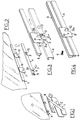
- Figure 1 is a simplified perspective view of a window regulator and a window before assembly of their respective sections.
- Figure 2 is a partial perspective view on an enlarged scale compared to Fig.1 of a first embodiment of the two profiles and their connecting device, before assembly.
- Figure 3 is a perspective view on an enlarged scale of the two profiles of Fig.2 immediately before their assembly.
- Figure 4 is a perspective view of the two profiles of Fig.3 in their assembled position immediately before installation of the fixing screws.
- Figure 5 is a perspective view similar to Fig.3 of the two profiles equipped with a connecting device according to a second embodiment of the invention.
- a window lifter 1 of the arm type 2, 3 whose upper ends carry a sliding section 4, intended to receive rollers not shown, in a manner known per se, as well as a window 5, the horizontal lower edge of which is fitted with a section 6 of the bottom of the glass, fixed to the latter.
- the sliding profile 4 is drilled with two holes 9 spaced apart by an interval equal to that of the holes 10, so that the two sections 4 and 6 can be assembled using suitable members such as screws 11 (Fig. 4) passing through the holes 9 and 10, when assembling the elements of the door on the chain mounting.
- connection system between the two sections 4 and 6 comprises means for automatic centering of the section 4 on the section 6, which in the example illustrated in FIGS. 2 to 4 are constituted in the following manner.
- the sliding profile 4 comprises a male part constituted by a lug 12 cut in the wall of the profile 4 and folded laterally at right angles.
- the bottom window profile 6 carries a female part constituted in this example by one of the lugs 8 in the lower edge of which has been formed a notch 13 having substantially an inverted V profile.
- the edges 13a, 13b of this notch form ramps for guiding the projecting tab 12 and therefore of the sliding profile 4, when the latter is moved upwards, as indicated by the arrow F.
- the guide ramps 13a and 13b may moreover not be identical, as shown in FIGS.
- the ramp of left 13a is in two sections: the first section, connected to the horizontal lower edge of the tab 8 has an inclination on the horizontal less than that of the second section which ends at the top of the V, in order to facilitate the sliding of the tab 12 on the first section of the ramp 13a.
- the profile 4 is provided, in a manner known per se, at one of its ends, with an internal stop 19 adapted to cooperate with a roller 20 carried by one of the arms 2, 3, for example the arm 3, in order to preset the position of profile 4 relative to that of profile 6.
- the assembly of the two sections 4 and 6 can be done automatically in a very simple manner: the V formed by the notch 13 being open at the bottom, and the section 4 being first positioned as indicated above, by coming from the roller 20 in contact with the stopper 19, its projecting tab 12 is inside a zone of width d equal to the distance between the opposite edges of the notch 13; the profile 4 is then moved upwards (arrow F). Therefore, the sliding of the tab 12 on the two successive sections of the ramp 13a, or on the second ramp 13b, brings the tab 12 into abutment in the bottom of the notch 13, and by the same positions the profile 4 in such a way that its holes 9 are in exact coincidence with the threaded holes 10 of the profile 6 (Fig.4). It then only remains for the operator to place the screws 11 (or possibly other fixing members) in the holes 9 and 10.
- the bottom window profile 6 carries two identical tabs 7, while in the sliding profile 4 are formed two lateral clearances 14 and 15.
- the clearing 14 is formed in the region of the profile 4 corresponding to the position of the plate 7 on the left when the two profiles 4 and 6 are assembled, while the clearance 15 is formed at the end of the profile 4 located opposite the second plate 7.
- the clearance 14 is delimited on each side, in the longitudinal direction of the profile 4, by two ramps 16 inclined towards one another, symmetrical with respect to a transverse plane passing through the middle of the bottom of the clearance 14 connecting these ramps 16.
- the terminal clearance 15 is delimited on one side by an inclined ramp 17, and on the other by a projecting tab 18, folded at a right angle and capable of forming a stop for the corresponding plate 7.
- the assembly of the two sections 4 and 6 is done in the following manner: the section 6 being kept fixed, the section 4 is raised so that the clearances 14, 15 are substantially placed opposite the legs 7. Due to the offset in the longitudinal direction (assumed to the left in the drawing) between the tabs 7 and the recesses 14, 15, the tabs 7 slide on the ramps 16 and 17 until they come to rest on the bottoms of the recesses 14 , 15, this longitudinal displacement of the profile 4 being stopped by the stop constituted by the tab 18, and when the tabs 7 come to bear on the dishes formed by the clearances 14 and 15. At this time, the holes 9 and 10 are in perfect coincidence and the operator can install screws 11.
- the invention is not limited to the embodiments described and may include variant embodiments.
- the profiles of the ramps 13a and 13b may vary, insofar as these ramps retain their function of guiding the movement of the profile 4 relative to the profile 6.
- the invention is applicable to the various existing types of window regulator : window winder with arm (Fig. 1), with cable-rack or cable.
Landscapes
- Engineering & Computer Science (AREA)
- Mechanical Engineering (AREA)
- Window Of Vehicle (AREA)
- Power-Operated Mechanisms For Wings (AREA)
Applications Claiming Priority (2)
| Application Number | Priority Date | Filing Date | Title |
|---|---|---|---|
| FR9004189A FR2660255B1 (fr) | 1990-04-02 | 1990-04-02 | Dispositif de liaison entre un profile de bas de vitre de porte de vehicule et un profile de coulissement de leve-vitre, et porte de vehicule equipee de ce dispositif. |
| FR9004189 | 1990-04-02 |
Publications (2)
| Publication Number | Publication Date |
|---|---|
| EP0451019A1 EP0451019A1 (fr) | 1991-10-09 |
| EP0451019B1 true EP0451019B1 (fr) | 1994-06-01 |
Family
ID=9395353
Family Applications (1)
| Application Number | Title | Priority Date | Filing Date |
|---|---|---|---|
| EP91400816A Expired - Lifetime EP0451019B1 (fr) | 1990-04-02 | 1991-03-26 | Dispositif de liaison entre un profilé de bas de vitre de porte de véhicule et un profilé de coulissement de lève-vitre, et porte de véhicule équipée de ce dispositif |
Country Status (8)
| Country | Link |
|---|---|
| US (1) | US5113620A (es) |
| EP (1) | EP0451019B1 (es) |
| JP (1) | JPH0717243A (es) |
| BR (1) | BR9101287A (es) |
| CA (1) | CA2039504A1 (es) |
| DE (1) | DE69102188T2 (es) |
| ES (1) | ES2055970T3 (es) |
| FR (1) | FR2660255B1 (es) |
Families Citing this family (10)
| Publication number | Priority date | Publication date | Assignee | Title |
|---|---|---|---|---|
| US5622005A (en) * | 1995-11-06 | 1997-04-22 | General Motors Corporation | Automotive door glass assembly |
| GB2319050B (en) * | 1996-10-15 | 2000-11-15 | Nissan Europ Technology Ct Ltd | Glass holding means and carrier plate for a vehicle window regulator |
| KR100196412B1 (en) * | 1996-12-16 | 1999-06-15 | Hyundai Motor Co Ltd | Door side impact structure |
| US6119401A (en) * | 1998-07-31 | 2000-09-19 | Hi-Lex Corporation | Dual-slider window regulator with three flexible, inextensible drive members |
| US6125585A (en) * | 1999-08-16 | 2000-10-03 | Hi-Lex Corporation | Sliding window regulator |
| US6330764B1 (en) | 1999-11-19 | 2001-12-18 | Larry G. Klosterman | Door window mounting and regulator assembly and method for assembly |
| DE60110663T2 (de) | 2000-03-10 | 2006-02-02 | Arvinmeritor Light Vehicle Systems-France | Verfahren und Gerät zum Montieren eines Antriebsmechanismus in einem Türmodul |
| GB0102987D0 (en) | 2001-02-07 | 2001-03-21 | Meritor Light Vehicle Sys Ltd | An assembly |
| US20070261181A1 (en) * | 2005-11-04 | 2007-11-15 | Willard Stephen E | Telescoping ramp stored upon tailgate |
| US8650800B2 (en) * | 2012-03-09 | 2014-02-18 | Toyota Motor Engineering & Manufacturing North America, Inc. | Window lift assemblies for vehicles including window support bracket assemblies |
Family Cites Families (10)
| Publication number | Priority date | Publication date | Assignee | Title |
|---|---|---|---|---|
| US3050332A (en) * | 1960-03-18 | 1962-08-21 | Gen Motors Corp | Window and window frame structure |
| JPS58417A (ja) * | 1981-06-20 | 1983-01-05 | Hori Glass Kk | 自動車用窓ガラスの保持装置 |
| JPS5810868U (ja) * | 1981-07-13 | 1983-01-24 | 花王株式会社 | スプレイヤ− |
| JPS5826623A (ja) * | 1981-08-08 | 1983-02-17 | Hori Glass Kk | 自動車用窓ガラスのホルダ− |
| JPS5826624A (ja) * | 1981-08-08 | 1983-02-17 | Hori Glass Kk | 自動車用窓ガラスのホルダ− |
| JPS5872855A (ja) * | 1981-10-23 | 1983-04-30 | 株式会社日立製作所 | 吸収式空調機 |
| US4943179A (en) * | 1986-06-27 | 1990-07-24 | Central Glass Company, Limited | Plate member arrangement |
| US4811519A (en) * | 1988-07-05 | 1989-03-14 | Gold Peter N | Automotive window mounting assembly |
| FR2637009A1 (fr) * | 1988-09-26 | 1990-03-30 | Rockwell Cim | Dispositif de liaison entre une vitre et un bras de leve-vitre dans une porte de vehicule |
| FR2637011B1 (fr) * | 1988-09-29 | 1995-06-30 | Rockwell Cim | Dispositif d'accouplement coulissant entre une vitre et un mecanisme de leve-vitre dans un vehicule |
-
1990
- 1990-04-02 FR FR9004189A patent/FR2660255B1/fr not_active Expired - Lifetime
-
1991
- 1991-03-26 EP EP91400816A patent/EP0451019B1/fr not_active Expired - Lifetime
- 1991-03-26 DE DE69102188T patent/DE69102188T2/de not_active Expired - Fee Related
- 1991-03-26 ES ES91400816T patent/ES2055970T3/es not_active Expired - Lifetime
- 1991-04-01 US US07/678,505 patent/US5113620A/en not_active Expired - Lifetime
- 1991-04-01 BR BR919101287A patent/BR9101287A/pt not_active Application Discontinuation
- 1991-04-02 CA CA002039504A patent/CA2039504A1/en not_active Abandoned
- 1991-04-02 JP JP3144292A patent/JPH0717243A/ja active Pending
Non-Patent Citations (1)
| Title |
|---|
| & JP-A-58 26623 (HORI GLASS) 17 février 1983, * |
Also Published As
| Publication number | Publication date |
|---|---|
| DE69102188T2 (de) | 1994-09-08 |
| FR2660255A1 (fr) | 1991-10-04 |
| FR2660255B1 (fr) | 1992-07-24 |
| CA2039504A1 (en) | 1991-10-03 |
| US5113620A (en) | 1992-05-19 |
| EP0451019A1 (fr) | 1991-10-09 |
| JPH0717243A (ja) | 1995-01-20 |
| BR9101287A (pt) | 1991-11-26 |
| ES2055970T3 (es) | 1994-09-01 |
| DE69102188D1 (de) | 1994-07-07 |
Similar Documents
| Publication | Publication Date | Title |
|---|---|---|
| EP3323958B1 (fr) | Agencement pour la fixation d'un panneau dans une rainure au moyen de deux coins opposés | |
| EP0451019B1 (fr) | Dispositif de liaison entre un profilé de bas de vitre de porte de véhicule et un profilé de coulissement de lève-vitre, et porte de véhicule équipée de ce dispositif | |
| EP0115353B1 (fr) | Dispositif destiné à déplacer, devant des moyens d'usinage et dans le sens de sa longueur un profilé à usiner | |
| EP0720935A1 (fr) | Dispositif pour le positionnement précis d'une pièce de carrosserie de véhicule par rapport à une autre pièce de carrosserie | |
| EP0250344A1 (fr) | Installation pour la réparation et le contrôle de carrosseries de véhicules accidentés | |
| EP1574422B1 (fr) | Traverse pour véhicule automobile et véhicule associé | |
| EP0083270B1 (fr) | Dérailleur à chape réglable pour pédalier | |
| EP1131240B1 (fr) | Procede et dispositif pour la mise en geometrie des elements de carrosserie de la face avant d'un vehicule automobile | |
| EP0419383A1 (fr) | Dispositif de fixation d'un véhicule et de réglage de sa position sur un châssis en vue de sa réparation | |
| FR2587058A1 (fr) | Dispositif d'assemblage et d'articulation pour porte montee sur pivot | |
| EP0594475B1 (fr) | Compas-charnière pour fenêtre à l'italienne | |
| FR2587942A1 (fr) | Toit ouvrant coulissant pour vehicules automobiles | |
| EP0220967B1 (fr) | Convoyeur de récipients | |
| EP0702443B1 (fr) | Dispositif de support pour appareillage à rapporter sur un corps de goulotte | |
| FR2530557A1 (fr) | Dispositif de blocage pour deux couples de glissieres d'un siege de vehicule automobile | |
| EP2103464B1 (fr) | Ensemble de guidage de vitre amélioré pour portière de véhicule automobile | |
| EP0707996A1 (fr) | Procédé de fixation d'une buse sur un radiateur de refroidissement | |
| EP4049798B1 (fr) | Support polyvalent pour manutention de porte automobile et methode de manutention | |
| FR2681025A1 (fr) | Balai d'essuie-glace comportant des moyens d'arret longitudinal de la lame d'essuyage. | |
| FR2962969A1 (fr) | Pion assurant le maintien en position d'un element rapporte destine a etre fixe sur une caisse de vehicule automobile. | |
| FR2951476A1 (fr) | Dispositif de couverture d’un faite de mur | |
| FR3055254A1 (fr) | Dispositif de guidage d’une vitre mobile montee dans la porte d’un vehicule, notamment automobile | |
| FR2705605A1 (fr) | Dispositif de démontage d'une porte de véhicule automobile, par soulèvement axial à l'aide d'un robot. | |
| FR2505223A1 (fr) | Table de coupe pour metal en feuille, en particulier zinc | |
| FR2698592A1 (fr) | Agencement pour la fixation amovible d'un siège sur le support plancher d'un véhicule automobile. |
Legal Events
| Date | Code | Title | Description |
|---|---|---|---|
| PUAI | Public reference made under article 153(3) epc to a published international application that has entered the european phase |
Free format text: ORIGINAL CODE: 0009012 |
|
| AK | Designated contracting states |
Kind code of ref document: A1 Designated state(s): DE ES GB IT SE |
|
| 17P | Request for examination filed |
Effective date: 19920304 |
|
| 17Q | First examination report despatched |
Effective date: 19930705 |
|
| RAP1 | Party data changed (applicant data changed or rights of an application transferred) |
Owner name: ROCKWELL BODY AND CHASSIS SYSTEMS - FRANCE, EN ABR |
|
| GRAA | (expected) grant |
Free format text: ORIGINAL CODE: 0009210 |
|
| AK | Designated contracting states |
Kind code of ref document: B1 Designated state(s): DE ES GB IT SE |
|
| ITF | It: translation for a ep patent filed | ||
| REF | Corresponds to: |
Ref document number: 69102188 Country of ref document: DE Date of ref document: 19940707 |
|
| REG | Reference to a national code |
Ref country code: ES Ref legal event code: FG2A Ref document number: 2055970 Country of ref document: ES Kind code of ref document: T3 |
|
| GBT | Gb: translation of ep patent filed (gb section 77(6)(a)/1977) |
Effective date: 19940906 |
|
| EAL | Se: european patent in force in sweden |
Ref document number: 91400816.4 |
|
| PGFP | Annual fee paid to national office [announced via postgrant information from national office to epo] |
Ref country code: ES Payment date: 19950315 Year of fee payment: 5 |
|
| PG25 | Lapsed in a contracting state [announced via postgrant information from national office to epo] |
Ref country code: GB Effective date: 19950326 |
|
| PG25 | Lapsed in a contracting state [announced via postgrant information from national office to epo] |
Ref country code: SE Effective date: 19950327 |
|
| PLBE | No opposition filed within time limit |
Free format text: ORIGINAL CODE: 0009261 |
|
| STAA | Information on the status of an ep patent application or granted ep patent |
Free format text: STATUS: NO OPPOSITION FILED WITHIN TIME LIMIT |
|
| 26N | No opposition filed | ||
| GBPC | Gb: european patent ceased through non-payment of renewal fee |
Effective date: 19950326 |
|
| EUG | Se: european patent has lapsed |
Ref document number: 91400816.4 |
|
| PG25 | Lapsed in a contracting state [announced via postgrant information from national office to epo] |
Ref country code: ES Free format text: LAPSE BECAUSE OF NON-PAYMENT OF DUE FEES Effective date: 19960327 |
|
| PGFP | Annual fee paid to national office [announced via postgrant information from national office to epo] |
Ref country code: DE Payment date: 19970221 Year of fee payment: 7 |
|
| PG25 | Lapsed in a contracting state [announced via postgrant information from national office to epo] |
Ref country code: DE Free format text: LAPSE BECAUSE OF NON-PAYMENT OF DUE FEES Effective date: 19981201 |
|
| REG | Reference to a national code |
Ref country code: ES Ref legal event code: FD2A Effective date: 19990503 |
|
| PG25 | Lapsed in a contracting state [announced via postgrant information from national office to epo] |
Ref country code: IT Free format text: LAPSE BECAUSE OF NON-PAYMENT OF DUE FEES;WARNING: LAPSES OF ITALIAN PATENTS WITH EFFECTIVE DATE BEFORE 2007 MAY HAVE OCCURRED AT ANY TIME BEFORE 2007. THE CORRECT EFFECTIVE DATE MAY BE DIFFERENT FROM THE ONE RECORDED. Effective date: 20050326 |