EP0450109B1 - Réservoir pour liquide avec une rigole - Google Patents
Réservoir pour liquide avec une rigole Download PDFInfo
- Publication number
- EP0450109B1 EP0450109B1 EP90106223A EP90106223A EP0450109B1 EP 0450109 B1 EP0450109 B1 EP 0450109B1 EP 90106223 A EP90106223 A EP 90106223A EP 90106223 A EP90106223 A EP 90106223A EP 0450109 B1 EP0450109 B1 EP 0450109B1
- Authority
- EP
- European Patent Office
- Prior art keywords
- float
- liquid
- discharge channel
- accordance
- weir
- Prior art date
- Legal status (The legal status is an assumption and is not a legal conclusion. Google has not performed a legal analysis and makes no representation as to the accuracy of the status listed.)
- Expired - Lifetime
Links
Images
Classifications
-
- B—PERFORMING OPERATIONS; TRANSPORTING
- B01—PHYSICAL OR CHEMICAL PROCESSES OR APPARATUS IN GENERAL
- B01D—SEPARATION
- B01D21/00—Separation of suspended solid particles from liquids by sedimentation
- B01D21/24—Feed or discharge mechanisms for settling tanks
- B01D21/2444—Discharge mechanisms for the classified liquid
-
- B—PERFORMING OPERATIONS; TRANSPORTING
- B01—PHYSICAL OR CHEMICAL PROCESSES OR APPARATUS IN GENERAL
- B01D—SEPARATION
- B01D17/00—Separation of liquids, not provided for elsewhere, e.g. by thermal diffusion
- B01D17/02—Separation of non-miscible liquids
- B01D17/0208—Separation of non-miscible liquids by sedimentation
- B01D17/0214—Separation of non-miscible liquids by sedimentation with removal of one of the phases
-
- B—PERFORMING OPERATIONS; TRANSPORTING
- B01—PHYSICAL OR CHEMICAL PROCESSES OR APPARATUS IN GENERAL
- B01D—SEPARATION
- B01D21/00—Separation of suspended solid particles from liquids by sedimentation
- B01D21/24—Feed or discharge mechanisms for settling tanks
- B01D21/2433—Discharge mechanisms for floating particles
-
- E—FIXED CONSTRUCTIONS
- E02—HYDRAULIC ENGINEERING; FOUNDATIONS; SOIL SHIFTING
- E02B—HYDRAULIC ENGINEERING
- E02B15/00—Cleaning or keeping clear the surface of open water; Apparatus therefor
- E02B15/04—Devices for cleaning or keeping clear the surface of open water from oil or like floating materials by separating or removing these materials
- E02B15/10—Devices for removing the material from the surface
- E02B15/106—Overflow skimmers with suction heads; suction heads
-
- E—FIXED CONSTRUCTIONS
- E02—HYDRAULIC ENGINEERING; FOUNDATIONS; SOIL SHIFTING
- E02B—HYDRAULIC ENGINEERING
- E02B8/00—Details of barrages or weirs ; Energy dissipating devices carried by lock or dry-dock gates
- E02B8/06—Spillways; Devices for dissipation of energy, e.g. for reducing eddies also for lock or dry-dock gates
Definitions
- the invention relates to a device for removing liquids and floating substances from a liquid surface with an outlet channel, a height-adjustable weir separating the outlet channel from the liquid surface and a float operatively connected to the weir.
- Devices of the type mentioned at the outset are used in particular in settling tanks from which precisely controllable amounts of liquid are to be removed. In this case, in particular, it is necessary to remove floating substances that are on the surface of the liquid.
- the height-adjustable weir is designed in the form of an overflow edge, the height of which is adjusted from a scraper bridge, for example using a spindle. It proves to be disadvantageous that in the event of fluctuations in the filling level of the liquid in the container, the overflow edge has to be adjusted either by hand or by means of complex electronic devices. If this is not done, either too much or no amount of liquid is drained off, which on the one hand leads to an excessive loss of liquid and on the other hand leads to the fact that the substances floating on the surface cannot be removed.
- Another disadvantage of this known embodiment is that inaccuracies in the structure, in particular the upper edges of mobile scraper bridges, prevent an exact setting of the amount of liquid to be discharged.
- a float is attached to the overflow edge itself, which moves the overflow edge upwards due to its buoyancy and thus closes.
- operating states can occur in which the float opens the overflow edge or the weir instead of closing it, so that a targeted control of the amount of liquid discharged is not possible.
- the invention has for its object to provide a device of the type mentioned, which is simple and reliable and in which a reliable, adjustable discharge of liquid is made possible.
- the object is achieved in that the interior of the float is connected to the drain channel by means of a communicating tube, that the weir is designed in the form of a wall of the drain channel which can be pivoted by means of a joint, and that the pivotable wall is rigidly connected to the float via a bearing arm is.
- the joint can be designed, for example, in the form of a liquid-tight, elastic connection layer be.
- the pivotable wall of the drainage channel is a Has overflow edge.
- the float is mounted on the bearing arm in an adjustable manner. The float can be adjusted to adjust the amount of liquid to be drained and to determine it for the subsequent process.
- an overflow weir is arranged in the outlet region of the outlet channel.
- the device according to the invention is distinguished by a number of considerable advantages. Since the interior of the float is in fluid communication with the interior of the drain channel, it is possible to control the position of the float and thus the height-variable weir via the amount of liquid in the drain channel. For example, it is possible to design the operational connection between the float and the height-adjustable weir so that when a certain amount of liquid or a certain liquid level in the discharge channel is exceeded, the float changes its buoyancy behavior due to the liquid entering it via the communicating tube, and that height-adjustable weir lifts and closes. According to the invention, it is thus possible to adjust the amount of liquid to be drained off in each case by adjusting the position of the float.
- the tube opens at one end in the bottom region of the drain channel.
- the drain channel is emptied, it is also possible to completely empty the float as well.
- the tube opens at a distance from the bottom of the drain channel.
- a predetermined liquid level is thus always maintained in the discharge channel, so that it is possible to discharge a presettable amount of liquid.
- the float is only activated when this amount of liquid is exceeded, i.e. at a higher liquid level in the discharge channel, run full of liquid and cause the weir to close.
- the tube is preferably designed in the form of a flexible hose which can open, for example, in the bottom region of the hollow float body. With this embodiment there is no impairment of the mobility of the swimmer through the communicating tube.
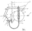
- FIG. 1 schematically shows a side view of the area of a device according to the invention in a liquid container, which is provided with a drain channel 1.
- the drain channel 1 is shown in section in FIG. 1; the walls of the liquid container have not been shown for reasons of clarification of the present invention.
- the drain channel 1 has a bottom 6 and a rear wall 11 firmly connected to it.
- the wall of the drain channel 1 opposite the rear wall 11 is provided in its central region with a joint or hinge which is liquid-tight and supports a pivotable wall 2 of the drain channel 1.
- the drainage channel 1 is arranged over most of its height so that it is below the liquid level 12 of the liquid in the liquid container.
- a communicating tube 4 in the form of a tube, which ends 5 in the interior of the drain channel 1.
- the other end 13 of the hose 4 opens into the interior of a float 3, which is arranged on the side of the drain channel 1 facing away from the pivotable wall 2.
- the float 3 is rigidly connected to the pivotable wall 2 via a bearing arm 9, so that a vertical movement of the float 3 leads to a pivoting of the weir or the pivotable wall 2.
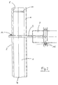
- FIG. 2 shows a top view of the arrangement shown in FIG. 1. It can be seen in particular that, as also shown in FIG. 1, the pivotable wall 2 of the drain channel 1 is provided with an overflow edge 8, which ensures a uniform, preferably laminar flow into the drain channel 1.
- connection between the bearing arm 9 and the pivotable wall 2 of the outlet channel 1 can, as shown in FIG. 2, take place by means of a screw connection 14 in order to enable adjustability during the assembly of the liquid container.
- the float 3 can take any shape, but for reasons of simplified production it is expedient to make it cylindrical or cuboid.
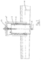
- the end of the bearing arm 9 facing the float 3 is connected to a U-shaped frame 15 (see FIG. 3), in which the float 3 is guided such that it can be adjusted in height, for example by means of lateral rail elements 16, not shown in detail.
- the area of the frame 15 has an adjusting spindle 17 which is rotatably mounted on the frame 15 and which fits into a threaded recess the float 3 is introduced. By rotating the threaded spindle 17, it is possible to adjust the height setting of the float 3 relative to the frame 15 and thus the bearing arm 9.
- the drain channel 1 has a slope so that the liquid entering it is drained off.
- an overflow weir 10 is also shown, which can be used in the interior of the drain channel 1.
- the overflow weir 10 which is designed to be removable and the height of which can be adjusted, makes it possible to vary the liquid level in the outlet channel 1, in order in this way to adapt the amount of liquid entering the float 1.
- the buoyancy of the float 3 is reduced, so that the pivotable wall 2 always remains open to a certain extent, so that an adapted amount of liquid flows continuously into the outlet channel 1.
- the buoyancy of the float 3 continues to decrease, so that the pivotable wall 2 or the weir is closed.
- the arrangement according to the invention ensures that the float can pivot about the pivot axis of the hinge or joint 7, so that jamming of the float 3 is prevented.
- the drain channel 1 is subsequently emptied, the amount of liquid in the float 3 also runs off, so that its buoyancy is increased again, so that the control process just described can take place again.
Landscapes
- Engineering & Computer Science (AREA)
- General Engineering & Computer Science (AREA)
- Chemical Kinetics & Catalysis (AREA)
- Chemical & Material Sciences (AREA)
- Civil Engineering (AREA)
- Structural Engineering (AREA)
- Mechanical Engineering (AREA)
- Physics & Mathematics (AREA)
- Thermal Sciences (AREA)
- Environmental & Geological Engineering (AREA)
- Float Valves (AREA)
- Removal Of Floating Material (AREA)
- Flow Control (AREA)
- Hydroponics (AREA)
- Containers And Packaging Bodies Having A Special Means To Remove Contents (AREA)
- Infusion, Injection, And Reservoir Apparatuses (AREA)
- Thermally Insulated Containers For Foods (AREA)
Claims (9)
- Dispositif pour enlever des liquides et des matières surnageantes d'une surface de liquide (12), comprenant un canal d'évacuation (1), un barrage réglable en hauteur qui sépare le canal d'évacuation (1) de la surface de liquide (12), et un flotteur (3) flottant sur la surface de liquide (12) et fonctionnellement relié au barrage, caractérisé en ce que l'intérieur du flotteur (3) est relié au canal d'évacuation (1) par l'intermédiaire d'un tuyau communicant (4), en ce que le barrage est réalisé sous la forme d'une paroi (2) du canal d'évacuation (1) qui peut pivoter grâce à une articulation (7), et en ce que la paroi pivotante (2) est rigidement reliée au flotteur (3) par l'intermédiaire d'un bras de liaison (9).
- Dispositif selon la revendication 1, caractérisé en ce que le tuyau (4) débouche, à une de ses extrémités, dans la région de fond du canal d'évacuation (1).
- Dispositif selon la revendication 1, caractérisé en ce que le tuyau (4) débouche à distance de la région de fond du canal d'évacuation (1).
- Dispositif selon l'une quelconque des revendications 1 à 3, caractérisé en ce que le tuyau (4) est réalisé sous forme de tuyau souple.
- Dispositif selon la revendication 1, caractérisé en ce que la paroi pivotante (2) présente une arête de déversement (8).
- Dispositif selon l'une quelconque des revendications 1 à 5, caractérisé en ce qu'un barrage déversoir (10) est disposé dans la région de sortie du canal d'évacuation (1).
- Dispositif selon l'une quelconque des revendications 1 à 6, caractérisé en ce que le canal d'évacuation (1) peut être vidé au moyen d'une pompe.
- Dispositif selon l'une quelconque des revendications 1 à 7, caractérisé en ce que le canal d'évacuation (1) présente une pente.
- Dispositif selon l'une quelconque des revendications 1 à 8, caractérisé en ce que le flotteur (3) est fixé au bras de liaison (9) avec possibilité de réglage en hauteur.
Priority Applications (4)
| Application Number | Priority Date | Filing Date | Title |
|---|---|---|---|
| DE3837707A DE3837707A1 (de) | 1988-11-07 | 1988-11-07 | Fluessigkeitsbehaelter mit einem ablaufkanal |
| AT90106223T ATE106024T1 (de) | 1988-11-07 | 1990-03-31 | Flüssigkeitsbehälter mit einem ablaufkanal. |
| DE59005823T DE59005823D1 (de) | 1988-11-07 | 1990-03-31 | Flüssigkeitsbehälter mit einem Ablaufkanal. |
| EP90106223A EP0450109B1 (fr) | 1988-11-07 | 1990-03-31 | Réservoir pour liquide avec une rigole |
Applications Claiming Priority (2)
| Application Number | Priority Date | Filing Date | Title |
|---|---|---|---|
| DE3837707A DE3837707A1 (de) | 1988-11-07 | 1988-11-07 | Fluessigkeitsbehaelter mit einem ablaufkanal |
| EP90106223A EP0450109B1 (fr) | 1988-11-07 | 1990-03-31 | Réservoir pour liquide avec une rigole |
Publications (2)
| Publication Number | Publication Date |
|---|---|
| EP0450109A1 EP0450109A1 (fr) | 1991-10-09 |
| EP0450109B1 true EP0450109B1 (fr) | 1994-05-25 |
Family
ID=25873994
Family Applications (1)
| Application Number | Title | Priority Date | Filing Date |
|---|---|---|---|
| EP90106223A Expired - Lifetime EP0450109B1 (fr) | 1988-11-07 | 1990-03-31 | Réservoir pour liquide avec une rigole |
Country Status (3)
| Country | Link |
|---|---|
| EP (1) | EP0450109B1 (fr) |
| AT (1) | ATE106024T1 (fr) |
| DE (2) | DE3837707A1 (fr) |
Families Citing this family (4)
| Publication number | Priority date | Publication date | Assignee | Title |
|---|---|---|---|---|
| DE4327235A1 (de) * | 1993-08-13 | 1994-01-13 | Ferdinand Diedrich | Überlaufeinrichtung mit fast vom Wasserstand unabhängigen Volumenstrom, insbesondere als Verbindungsglied zwischen den einzelnen Kammern einer Kläranlage |
| EP0748248B1 (fr) * | 1994-03-02 | 1997-10-29 | Bernd Glaser | Bassin de decantation |
| DE19717572A1 (de) * | 1997-04-25 | 1998-10-29 | Keld Gabelgaard | Skimmereinrichtung |
| DE19731264B4 (de) * | 1997-07-21 | 2005-09-01 | Emschergenossenschaft Lippeverband | Wasserabzug und/oder Schlammabzug in Absetzbecken |
Family Cites Families (5)
| Publication number | Priority date | Publication date | Assignee | Title |
|---|---|---|---|---|
| US2348938A (en) * | 1941-01-30 | 1944-05-16 | Sharples Corp | Skimming apparatus |
| GB2129697B (en) * | 1982-11-12 | 1986-07-02 | Stetfield Limited | Surface skimming device |
| DE3627119A1 (de) * | 1986-08-06 | 1988-02-11 | Passavant Werke | Schwimmstoffabzugsrinne |
| DE3642702A1 (de) * | 1986-12-13 | 1988-06-23 | Passavant Werke | Verfahren zum abziehen von schwimmstoffen von der oberflaeche von absitzbecken |
| EP0331807A1 (fr) * | 1988-02-25 | 1989-09-13 | Passavant-Werke Ag | Procédé de séparation des matières flottantes de la superficie d'un bac de sédimentation |
-
1988
- 1988-11-07 DE DE3837707A patent/DE3837707A1/de not_active Withdrawn
-
1990
- 1990-03-31 DE DE59005823T patent/DE59005823D1/de not_active Expired - Fee Related
- 1990-03-31 EP EP90106223A patent/EP0450109B1/fr not_active Expired - Lifetime
- 1990-03-31 AT AT90106223T patent/ATE106024T1/de not_active IP Right Cessation
Also Published As
| Publication number | Publication date |
|---|---|
| EP0450109A1 (fr) | 1991-10-09 |
| DE3837707A1 (de) | 1990-05-10 |
| DE59005823D1 (de) | 1994-06-30 |
| ATE106024T1 (de) | 1994-06-15 |
Similar Documents
| Publication | Publication Date | Title |
|---|---|---|
| DE2523942C3 (de) | Drosselvorrichtung für den Auslauf von Flüssigkeits-Sammelbecken | |
| DE4211659C2 (de) | Vorrichtung zum Entfernen von Abscheidegut aus einerFlüssigkeit mit einer zylindermantelförmigen, flüssigkeitsdurchlässigen Abscheidefläche | |
| EP0450109B1 (fr) | Réservoir pour liquide avec une rigole | |
| DE3305409A1 (de) | Regenabschlagwerk | |
| EP0221349B1 (fr) | Dispositif de régulation | |
| EP0128122B2 (fr) | Dispositif d'écoulement d'un barrage ou d'un bac de sédimentation | |
| DE3202354A1 (de) | Vorrichtung fuer den fluessigkeitsabzug aus becken o.dgl. | |
| DE3305226C2 (de) | Schwimmergesteuerte Regelvorrichtung zum Verändern des Durchflußquerschnittes eines Abflußrohres eines Flüssigkeitsbeckens | |
| DE2406857A1 (de) | Vorrichtung fuer den fluessigkeitsabzug von der oberflaeche von becken o.dgl. | |
| DE3817444A1 (de) | Schwimmergesteuerte regelvorrichtung zur veraenderung des durchflussquerschnittes der auslaufoeffnung eines fluessigkeitsbehaelters, insbesondere eines regenrueckhaltebeckens | |
| EP0086749B1 (fr) | Bassin comprenant un bac de rinçage basculant et une paroi plongeante flottable | |
| DE3305227C2 (fr) | ||
| EP0029468B1 (fr) | Dispositif de filtration à nettoyage par contre-courant | |
| EP0518912B1 (fr) | Bassin d'epuration ou de sedimentation | |
| EP0668242A1 (fr) | Dispositif pour le prélèvement régulièrement distribué des eaux usées clarifiées dans la périphérie d'un bassin circulaire de sédimentation | |
| DE19816900C1 (de) | Vorrichtung zum Sammeln und Abgeben eines vorbestimmten Flüssigkeitsvolumens | |
| EP1138363A2 (fr) | Dispositif et procédé de soutirage d'eau purifiée d'un récipient lors de la purification biologique d'eaux usées | |
| DE3428500A1 (de) | Regenabschlagwerk | |
| DE102007016487B4 (de) | Flüssigkeitsreinigungsvorrichtung mit einer Steueranordnung | |
| WO1985001974A1 (fr) | Dispositif de reglage pour l'ecoulement d'un fluide a partir d'un recipient | |
| DE3809706C2 (de) | Klärschlammabzugsvorrichtung | |
| DE2504769A1 (de) | Vorrichtung zum erzeugen von salzloesung fuer das regenerieren von ionenaustauschharzen einer wasseraufbereitungsanlage | |
| DE2452906A1 (de) | Rueckspuel-ventilanordnung zum regenerieren von ionenaustauschmaterial | |
| EP0742036A2 (fr) | Séparateur de liquides légers | |
| DE19527970A1 (de) | Kläranlage, insbesondere Bodenfilterkläranlage |
Legal Events
| Date | Code | Title | Description |
|---|---|---|---|
| PUAI | Public reference made under article 153(3) epc to a published international application that has entered the european phase |
Free format text: ORIGINAL CODE: 0009012 |
|
| 17P | Request for examination filed |
Effective date: 19910205 |
|
| AK | Designated contracting states |
Kind code of ref document: A1 Designated state(s): AT BE CH DE DK FR GB IT LI LU NL SE |
|
| 17Q | First examination report despatched |
Effective date: 19920605 |
|
| GRAA | (expected) grant |
Free format text: ORIGINAL CODE: 0009210 |
|
| AK | Designated contracting states |
Kind code of ref document: B1 Designated state(s): AT BE CH DE DK FR GB IT LI LU NL SE |
|
| PG25 | Lapsed in a contracting state [announced via postgrant information from national office to epo] |
Ref country code: IT Free format text: LAPSE BECAUSE OF FAILURE TO SUBMIT A TRANSLATION OF THE DESCRIPTION OR TO PAY THE FEE WITHIN THE PRE;WARNING: LAPSES OF ITALIAN PATENTS WITH EFFECTIVE DATE BEFORE 2007 MAY HAVE OCCURRED AT ANY TIME BEFORE 2007. THE CORRECT EFFECTIVE DATE MAY BE DIFFERENT FROM THE ONE RECORDED.SCRIBED TIME-LIMIT Effective date: 19940525 Ref country code: BE Effective date: 19940525 Ref country code: NL Effective date: 19940525 Ref country code: FR Effective date: 19940525 Ref country code: DK Effective date: 19940525 Ref country code: SE Free format text: THE PATENT HAS BEEN ANNULLED BY A DECISION OF A NATIONAL AUTHORITY Effective date: 19940525 Ref country code: GB Effective date: 19940525 |
|
| REF | Corresponds to: |
Ref document number: 106024 Country of ref document: AT Date of ref document: 19940615 Kind code of ref document: T |
|
| REF | Corresponds to: |
Ref document number: 59005823 Country of ref document: DE Date of ref document: 19940630 |
|
| EN | Fr: translation not filed | ||
| NLV1 | Nl: lapsed or annulled due to failure to fulfill the requirements of art. 29p and 29m of the patents act | ||
| GBV | Gb: ep patent (uk) treated as always having been void in accordance with gb section 77(7)/1977 [no translation filed] |
Effective date: 19940525 |
|
| PLBE | No opposition filed within time limit |
Free format text: ORIGINAL CODE: 0009261 |
|
| STAA | Information on the status of an ep patent application or granted ep patent |
Free format text: STATUS: NO OPPOSITION FILED WITHIN TIME LIMIT |
|
| PG25 | Lapsed in a contracting state [announced via postgrant information from national office to epo] |
Ref country code: LU Free format text: LAPSE BECAUSE OF NON-PAYMENT OF DUE FEES Effective date: 19950331 Ref country code: CH Effective date: 19950331 Ref country code: AT Effective date: 19950331 Ref country code: LI Effective date: 19950331 |
|
| 26N | No opposition filed | ||
| REG | Reference to a national code |
Ref country code: CH Ref legal event code: PL |
|
| PGFP | Annual fee paid to national office [announced via postgrant information from national office to epo] |
Ref country code: DE Payment date: 19990510 Year of fee payment: 10 |
|
| PG25 | Lapsed in a contracting state [announced via postgrant information from national office to epo] |
Ref country code: DE Free format text: LAPSE BECAUSE OF NON-PAYMENT OF DUE FEES Effective date: 20010103 |