EP0448633B1 - Procédé mettant en oeuvre un lit mobile simulé - Google Patents
Procédé mettant en oeuvre un lit mobile simulé Download PDFInfo
- Publication number
- EP0448633B1 EP0448633B1 EP90901343A EP90901343A EP0448633B1 EP 0448633 B1 EP0448633 B1 EP 0448633B1 EP 90901343 A EP90901343 A EP 90901343A EP 90901343 A EP90901343 A EP 90901343A EP 0448633 B1 EP0448633 B1 EP 0448633B1
- Authority
- EP
- European Patent Office
- Prior art keywords
- sorbent
- bed
- resin
- simulated moving
- loop
- Prior art date
- Legal status (The legal status is an assumption and is not a legal conclusion. Google has not performed a legal analysis and makes no representation as to the accuracy of the status listed.)
- Expired - Lifetime
Links
Images

Classifications
-
- B—PERFORMING OPERATIONS; TRANSPORTING
- B01—PHYSICAL OR CHEMICAL PROCESSES OR APPARATUS IN GENERAL
- B01D—SEPARATION
- B01D15/00—Separating processes involving the treatment of liquids with solid sorbents; Apparatus therefor
- B01D15/08—Selective adsorption, e.g. chromatography
- B01D15/10—Selective adsorption, e.g. chromatography characterised by constructional or operational features
- B01D15/18—Selective adsorption, e.g. chromatography characterised by constructional or operational features relating to flow patterns
- B01D15/1814—Selective adsorption, e.g. chromatography characterised by constructional or operational features relating to flow patterns recycling of the fraction to be distributed
- B01D15/1821—Simulated moving beds
-
- B—PERFORMING OPERATIONS; TRANSPORTING
- B01—PHYSICAL OR CHEMICAL PROCESSES OR APPARATUS IN GENERAL
- B01D—SEPARATION
- B01D2215/00—Separating processes involving the treatment of liquids with adsorbents
- B01D2215/02—Separating processes involving the treatment of liquids with adsorbents with moving adsorbents
- B01D2215/023—Simulated moving beds
Definitions
- This invention relates to an improvement in the preparation of the sorbent beds of a simulated moving bed chromatographic separator. It is particularly directed to a sorbent bed packing technique which reduces void volume and improves the separation characteristics of a simulated moving bed.
- a sorbent bed should be prepared in such a manner that no large voids exist in the compartment containing the sorbent. This preparation minimizes mixing inside the compartment and improves even plug flow across the compartment cross-section. It is also recognized that an increase in sorbent bed density can improve the separating efficiency of the sorbent bed.
- Sorbent bed systems representative of the types contemplated by this invention are disclosed in US-A-2,985,589; US-A-3,831,755; US-A-4,400,278; US-A-4,404,037; US-A-4,011,113; US-A-4,182,633; US-A-4,247,636; US-A-4,412,866; US-A-4,501,814; and US-A-4,511,476, These documents describe the use of such beds in industrial scale operations.
- U.S.-A-4,511,476 is specifically instructive concerning the mechanical manipulation of such beds.
- U.S.-A-4,366,060 and US-A-4,673,507 disclose techniques for shrinking and expanding resins useful for sorbent beds.
- Simulated moving bed (SMB) technology is well developed for applications involving separating the components of a fluid.
- Typical applications of simulated moving bed chromatography include the separation of fructose from fructose-glucose solutions and the separation of sucrose from sugar beet or sugar cane syrups.
- Ion exchange resins are typically employed as sorbents for these applications. Solution components are differentially absorbed by the ion exchange resin so that a separation waveform develops within the simulated moving bed.
- a typical simulated moving bed apparatus consists of several compartments (or individual columns) filled with solid sorbent.
- a fluid conduit interconnects the upstream and downstream ends of the system to form a loop through which fluid is continuously recirculated. The constant flow of fluid through the loop is called "internal recirculation flow.”
- a manifold system of pipes and valves is provided selectively to position an inlet for feed material, an inlet for desorbent, an outlet for a sorbed component and an outlet for a nonsorbed (or less sorbed) component. Each inlet and outlet communicates with a separate bed compartment. Feed material enters the system at a designated compartment and is moved through the sorbent by the continuous internal recirculation flow.
- Sorbed component(s) which flow(s) at a relatively slow rate is removed from the sorbed component outlet.
- Nonsorbed component(s) which flow(s) at a relatively fast rate is removed from the nonsorbed component outlet.
- Desorbent is added at its inlet valve between the respective outlet valve positions of the sorbed and nonsorbed components.
- step time the designated inlet and outlet valve positions are displaced downstream one position on the manifold to the next sorbent bed compartment, which may be a discrete section of a vessel, (such as a column), or an individual such vessel, e.g., column.
- the step time is chosen such that the designation of valves is properly synchronized with the internal recirculation flow. Under these conditions the system eventually reaches a steady state with specific product characteristics appearing at predetermined intervals in sequence at each valve position. This type of system simulates valves held in a single position while the solid sorbent moves at a constant and continuous rate around the recirculation loop producing constant quality product at each valve.
- the simulated version more closely approaches the character of an actual moving bed system as the number of compartments and valve positions increase.
- An important distinction between batch and simulated moving bed systems is that the internal recirculation flow is continuous in the simulated moving bed process. Except for very small adjustments to control internal pressure, the entering and exiting flow rates are continuous and constant, thereby approximating an actual moving bed system as closely as possible.
- This invention provides a sorbent bed packing procedure which minimizes sorbent bed compartment void space and provides a sorbent bed of increased density in a chromatographic separator operating on the principle of the simulated moving bed.
- a resin contraction procedure is employed.
- the present invention involves operating a simulated moving bed consisting of separate columns or compartments.
- the compartments are filled with a separation medium (sorbent), such as ion exchange resin.
- sorbent such as ion exchange resin.
- the simulated moving bed is operated such that an equilibrated separation waveform develops.
- equilibrated separation waveform refers to a steady state condition in which the plot of percent solids of a component versus circulation loop position retains approximately the same shape over time, although the individual points on the plot appear to rotate around the loop over time.
- the circulating waveform is monitored for the development of a resin contraction phase.
- resin contraction phase refers to a fluid composition revealed by the waveform known to interact with the sorbent material to cause shrinkage of that material.
- the rotation of the contraction phase through the simulating moving bed is also monitored.
- the equilibrated simulated moving bed system exhibits a steady state separation waveform along the path of the recirculation loop. This waveform rotates around the path of the recirculation loop with valve switching synchronized to maintain the desired steady state.
- the invention is applied to a simulated moving bed process in which a plurality of sorbent beds are contained within separate respective vessels (compartments) with inlets and outlets connected in a loop. Circulating liquid moves in sequence through the beds while process input streams are cyclically introduced in corresponding sequence to the loop at selected locations associated with the vessels. Compensating process outlet streams are withdrawn in similarly corresponding sequence from the loop at other selected locations associated with the vessels. A forward flow is maintained in a fixed direction through the loop during a plurality of cycles.
- the invention comprises operating such a simulated moving bed process to establish an equilibrated percent solids waveform whereby a contraction phase continuously moves through the loop; monitoring the position of the contraction phase in the loop over time; and introducing sorbent to a selected sorbent bed following the passage of the contraction phase through the bed while maintaining the forward flow through the loop.
- a discrete contraction phase is followed in the loop by a discrete desorbent phase.
- the contraction and desorbent phases thus flow in sequence through any particular bed.
- Sorbent is desirably added during the interval of time between contact of the bed by the respective discrete contraction and desorbent phases.
- the sorbent is most readily added in slurry form, ideally with the liquid phase of the slurry being similar in composition to the contraction phase.
- the sorbent is added to a bed by introducing sorbent to the top of the compartment containing the bed. As sorbent is added, liquid is displaced from the compartment, usually through a liquid distributor at the top of the compartment.
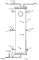
- Figure 1 illustrates a model separator cell 10 which was used for a number of test runs.
- the cell stood 2.74 meters tall and had a 0.61 meter diameter. It was filled with Dowex 99, a commercially available strong cation resin in potassium form.
- Three liquid distributors were positioned on the top plate and three liquid collectors were positioned on the bottom plate of the cell. The three collectors at the bottom were covered by several centimeters of sand to provide a more porous bed, and to protect the collectors from the resin.
- Liquid pressure gauges 11 were mounted on one side of the cell and diaphragm pressure gauges 12 were mounted directly opposite. Strain gauges 13 were mounted in various places as shown, and they measured the horizontal and vertical strain on the cell at those points.
- the entire cell 10 was insulated to ensure isothermal results, and the cell was operated under a downflow condition.
- a positive displacement pump (not shown) was used to pump water or syrup at 22.7-30.3 liters per minute (LPM).
- a positive displacement tubing pump (not shown) was used to pump resin from 18.9 liter buckets.
- the operating temperature for the tests ranged from 78°C to 83°C, as measured at temperature sensors 14.
- the empty cell was initially filled with water and operated at various pressures to enable the investigators to become familiar with the equipment, and to observe the liquid, diaphragm, and temperature gauges.
- the liquid and diaphragm pressure gauges displayed the same pressure readings from 0 kilopascals up to 310 kilopascals.
- the cell was then filled with resin and it was determined that the cell was free from air pockets.
- the diaphragm gauges read a higher pressure than the liquid gauges.
- the resin was removed to a level of 5.08 centimeters below both pressure gauges.
- a wood dowel was then wedged in place on the diaphragm of the diaphragm gauge, producing an artificial 55.14 kilopascals reading on the gauge. This artificial reading represented a mechanical pressure, simulating a constant resin expansion.
- the exit valve was partially closed, forcing the top liquid pressure to rise to 55.14 kilopascals.
- the recorded pressures in Table 1 show that a 41.35-55.14 kilopascals increase in liquid pressure resulted in a 41.35-62.0 kilopascals increase in the diaphragm pressure.
- the diaphragm pressure reading minus the liquid pressure reading equals the mechanical pressure due to resin expansion.
- the cell was then filled with resin slurried in water.
- the cell was heated with recirculating hot water.
- 40 RDS syrup was pumped through the cell to shrink the resin.
- the top of the cell was opened and resin shrinkage was observed.
- the top was then closed, and the resin was rinsed with circulating water.
- the resin was observed to expand back to its original size. This test was designated an "unpacked test.”
- Table 3 shows that the mechanical pressure dropped along the whole column as the 40 RDS syrup was pumped through, indicating resin shrinkage.
- the liquid pressure drop across the cell increased from 0.0-55.14 kilopascals, but visual inspection, after the top of the cell was opened, revealed very little resin shrinkage, about 0.94 centimeters.
- the cell Under “packed condition,” the cell was again heated with recirculating hot water, but 60 RDS syrup was used to shrink the resin. After the 60 RDS syrup had recirculated through the cell, the top was opened to observe the resin shrinkage. On several occasions the resin was observed to have shrunk 7.62-10.16 centimeters (3-4% of total volume). Then an additional 24 to 26 liters of resin was added to the cell, the top closed, and the cell rinsed off with water.
- This example shows that it is feasible to shrink the resin and pack the separator cells.
- the resin packing operation should be done such that the resin-water mixture enters the top of the cell with the water exiting through the top distributors. It is possible to identify when the cell is full of resin by the sharp rise in observable liquid pressure. It is preferable to repeat the resin shrinkage/packing operation, e.g., 2-3 times, to ensure a packed cell. It is significant that when the cell is rinsed with water, the most likely place for the development of high mechanical pressure, due to resin expansion, is in the bottom of the cell. The cell under packed conditions showed no evidence of an unusually high liquid pressure drop across the cell. It is feasible to shrink the resin with filtered 60 RDS sugar solution.
- Diaphragm gauges alone may not indicate that the resin has indeed shrunk. There were no distributor/collector plugging problems, either in the packed or unpacked cell condition. Tests were done with backwashing the resin in the cell, which allows the resin to intimately contact the distributors at the top, and still no plugging problems occurred. It is important to coat the inside of each cell to protect the resin from fouling and discoloration. There was no evidence of resin damage in the short term by packing the cell. Because heat alone has an effect on resin expansion, it is preferred to pack the cells under cooler conditions (e.g., 30-40°C) if possible to ensure a packed cell at higher temperatures (e.g., 80°C).
- cooler conditions e.g. 30-40°C
- kPa 68.9 110.3 55.1 Top liq. kPa 27.6 82.7 27.6 41.4 20.7 27.6 Mid diaph. kPa 103.4 110.3 89.6 Mid liq. kPa 34.5 62.0 34.5 68.9 48.2 55.1 Bot. diaph. kPa 110.3 82.7 117.1 Bot. liquid kPa 27.6 41.4 27.6 82.7 41.4 82.7 TABLE 4 AVERAGE PRESSURES PACKED CONDITIONS Heating Cell Pumping 60 RDS syrup Rinse Mechanical Pressures Heating Cell Pumping 60 RDS syrup Rinse Top diaph. kPa 68.9 186.0 62.0 Top liq.
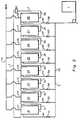
- FIG. 2 illustrates a typical embodiment of this invention.
- the simulated moving bed illustrated includes eight individual compartments, designated 21 through 28, respectively.
- Internal recirculating flow is established through the loop I including the compartments 21 through 28 connected in series through piping 31 through 38.
- a device M is provided in the loop I for monitoring the concentration of components in the recirculating flow. Typical monitoring instruments M include refractometers, conductivity meters or polarimeters.
- a sorbent pathway S comprising pipes 40 through 48 and valves 51 through 58, is used to pack the compartments 21 through 28.
- a packing sorbent tank T communicates with the sorbent pathway S through an appropriate sorbent pump P.
- a pathway R for displaced liquid destined for a recovery tank comprises piping 70 through 78.
- Individual compartments 21-28 may be partially packed by providing sight glasses (not shown) on each cell so that resin levels can be adjusted manually. Sight glasses also aid monitoring of the circulating contraction phase. Complete packing of created void can be accomplished by providing pressure gauges (not shown) near the top plate of the compartments and pumping resin into the created void until a positive mechanical pressure develops within the compartment as indicated by the gauges.
- the following procedure may be used to pack the individual compartments of a simulated moving bed process.
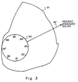
- FIGS. 3 through 5 illustrate the practice of this invention as applied to a simulated bed process of the type shown by FIG. 2.
- FIG. 3 is illustrative of the percent dry substance waveform which developed within a simulated moving bed system configured to demonstrate the invention.
- Points labeled 81 through 88 represent eight stationary points along the circular path 90 of the internal recirculation (I, FIG. 2).
- the distance between the circle 90 and the plot 91 as measured along the radius 92 represents the percent dissolved solids in the circulating fluid at a specific time at each point in the loop.
- the positions of the points 81 through 88 have been chosen arbitrarily, but with equal distance between any two neighboring points.
- each point 81 through 88 corresponds to the respective compartments 21 through 28 or associated piping 31 through 38, respectively.
- the physical size of the sorbent may also be differentially affected by the separate components.
- the fructose component is more strongly sorbed and the resin bead size decreases as the high fructose portion of the circulating waveform passes through a given section of the simulated moving bed.
- the resin size expands.
- the simulated moving bed in these applications can be viewed with respect to a resin bead size waveform circulating through the bed compartments. If the simulated moving bed is configured as separate columns or compartments (resin in each compartment isolated from the resin in other compartments) the system can be viewed as an oscillation of resin bed depth versus time in each of the columns or compartments.
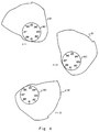
- the location of this phase at any time can be determined by monitoring the percent solids waveform 91 because the contraction phase occurs in the tail end 95 of the waveform, i.e., in the portion of the waveform which represents the sorbed component(s).
- the maximum contraction of resin observed in Example III was six percent, measured as an increase in the liquid freeboard above the resin level.
- the liquid in the created void at the top of the bed is displaced by pumping or otherwise drawing in additional sorbent resin into the created void area.
- slurried resin may be pumped from the tank T through the sorbent manifolds S.
- the liquid phase of the slurry exits out of the compartment distributors and is recovered through the manifold R. Bed packing is thus carried out during normal production without use of special reagents or off-line routines.
- the contraction phase A is approaching position 86, which may be assumed to correspond to the pipe 36 entering the compartment 26 of FIG. 2.
- the contraction phase A has moved past the compartment 26 and is entering compartment 25 (position 85, FIG. 5) and slurried resin may be pumped from the tank T through valve 56 and pipe 46 to the top of compartment 26, the excess liquid being displaced through the pipes 76 and 70.
- the desorbent portion 96 of the waveform 91 is shown in contact with position 86, indicating that desorbent has passed or is passing through the compartment 26, thereby causing expansion of the resin bed.
Landscapes
- Chemical & Material Sciences (AREA)
- Life Sciences & Earth Sciences (AREA)
- Sustainable Development (AREA)
- Analytical Chemistry (AREA)
- Chemical Kinetics & Catalysis (AREA)
- Treatment Of Liquids With Adsorbents In General (AREA)
- Mixers Of The Rotary Stirring Type (AREA)
- Processing And Handling Of Plastics And Other Materials For Molding In General (AREA)
- Preparation Of Clay, And Manufacture Of Mixtures Containing Clay Or Cement (AREA)
- Accommodation For Nursing Or Treatment Tables (AREA)
- Seats For Vehicles (AREA)
- Toys (AREA)
Claims (6)
- Procédé utilisant un lit mobile simulé, dans lequel plusieurs lits sorbants sont contenus au sein de récipients (21-28) respectifs, dont les entrées et les sorties sont reliées en une boucle (I, 90), de façon que le liquide en circulation se déplace en traversant successivement lesdits lits (21-28), cependant que les courants d'entrée dans le procédé (40, 41, 42, 43, 44, 45, 46, 47 et 48) sont introduits cycliquement en séquences correspondantes dans ladite boucle (I, 90) en des endroits choisis associés auxdits récipients, et des courants compensateurs de sortie du procédé (70, 71, 72, 73, 74, 75, 76, 77, 78) sont soutirés de ladite boucle (I, 90) en une séquence correspondante de façon similaire, en d'autres endroits choisis associés auxdits récipients, tout en maintenant un écoulement vers l'avant dans une direction fixe empruntant la boucle (I) au cours de plusieurs cycles, procédé caractérisé en ce que :- on fait fonctionner ledit procédé utilisant un lit mobile simulé de façon à établir une forme d'onde des solides en pourcentage équilibré,de sorte qu'une phase de contraction se déplace en continu dans ladite boucle (I) ;- on surveille la position de ladite phase de contraction dans ladite boucle (I, 90) au cours du temps ; et- on introduit du sorbant dans un lit choisi de sorbant, après le passage de ladite phase de contraction à travers ce lit, tout en maintenant ledit écoulement vers l'avant dans ladite boucle (I, 90).
- Procédé utilisant un lit mobile simulé, selon la revendication 1, dans lequel ledit liquide en circulation comprend une phase de contraction séparée suivie d'une phase de désorption séparée, lesdites phases de contraction et de désorption s'écoulant successivement en empruntant ledit lit choisi, et du sorbant est ajouté dans ledit lit choisi pendant l'intervalle de temps entre la venue desdites phases séparées respectives au contact dudit lit choisi.
- Procédé utilisant un lit mobile simulé selon la revendication 2, dans lequel du sorbant est ajouté sous forme de suspension, la phase liquide de ladite suspension ayant une composition semblable à celle de la phase en contraction.
- Procédé utilisant un lit mobile simulé selon la revendication 2, dans lequel chaque lit de sorbant est contenu dans un compartiment (21-28) séparé, et du sorbant est ajouté audit lit choisi,par introduction de sorbant au sommet du compartiment contenant ledit lit choisi.
- Procédé utilisant un lit mobile simulé selon la revendication 4, dans lequel du sorbant est ajouté successivement à chacun desdits plusieurs lits de sorbant, ce qui est suivi de la mise en contact successive de chaque lit avec ladite phase de contraction.
- Procédé utilisant un lit mobile simulé selon la revendication 5, dans lequel du sorbant est ajouté dans chaque lit de sorbant en étant sous forme d'une suspension dont la phase liquide a une composition semblable a celle de ladite phase de contraction, un distributeur étant prévu au sommet de chacun desdits compartiments, et l'excès de liquide résultant de l'introduction de ladite suspension étant déplacé dans ledit distributeur pour être récupéré à l'extérieur de ladite boucle.
Applications Claiming Priority (5)
| Application Number | Priority Date | Filing Date | Title |
|---|---|---|---|
| US285717 | 1981-07-22 | ||
| US28571788A | 1988-12-16 | 1988-12-16 | |
| US07/412,417 US4990259A (en) | 1988-12-16 | 1989-09-26 | Chromatographic separator sorbent bed preparation |
| US412417 | 1989-09-26 | ||
| PCT/US1989/005572 WO1990006796A1 (fr) | 1988-12-16 | 1989-12-14 | Amelioration apportee a la preparation des lits de sorbant d'un separateur chromatographique |
Publications (3)
| Publication Number | Publication Date |
|---|---|
| EP0448633A1 EP0448633A1 (fr) | 1991-10-02 |
| EP0448633A4 EP0448633A4 (en) | 1992-06-10 |
| EP0448633B1 true EP0448633B1 (fr) | 1996-04-17 |
Family
ID=26963344
Family Applications (1)
| Application Number | Title | Priority Date | Filing Date |
|---|---|---|---|
| EP90901343A Expired - Lifetime EP0448633B1 (fr) | 1988-12-16 | 1989-12-14 | Procédé mettant en oeuvre un lit mobile simulé |
Country Status (8)
| Country | Link |
|---|---|
| US (1) | US4990259A (fr) |
| EP (1) | EP0448633B1 (fr) |
| JP (1) | JPH0734010B2 (fr) |
| AT (1) | ATE136805T1 (fr) |
| AU (1) | AU4815690A (fr) |
| CA (1) | CA2005702C (fr) |
| DE (1) | DE68926308D1 (fr) |
| WO (1) | WO1990006796A1 (fr) |
Families Citing this family (39)
| Publication number | Priority date | Publication date | Assignee | Title |
|---|---|---|---|---|
| FR2651149B1 (fr) * | 1989-08-28 | 1992-06-05 | Inst Francais Du Petrole | Procede continu et dispositif de separation chromatographique d'un melange d'au moins trois constituants en trois effluents purifies au moyen d'un seul solvant a deux temperatures et/ou a deux pressions differentes. |
| FR2651148B1 (fr) * | 1989-08-28 | 1992-05-07 | Inst Francais Du Petrole | Procede continu et dispositif de separation chromatographique d'un melange d'au moins trois constituants en trois effluents purifies au moyen de deux solvants. |
| FI86440C (fi) | 1990-01-15 | 1992-08-25 | Cultor Oy | Foerfarande foer samtidig framstaellning av xylitol och etanol. |
| US7109005B2 (en) | 1990-01-15 | 2006-09-19 | Danisco Sweeteners Oy | Process for the simultaneous production of xylitol and ethanol |
| US5200075A (en) * | 1991-03-08 | 1993-04-06 | Nkk Corporation | Separator |
| JP2962594B2 (ja) * | 1991-06-12 | 1999-10-12 | オルガノ株式会社 | 複数成分の分離方法 |
| US5241998A (en) * | 1991-10-30 | 1993-09-07 | Suprex Corporation | Apparatus and method for packing particles |
| DE69323382T2 (de) * | 1992-04-29 | 1999-06-10 | Inst Francais Du Petrole | Verfahren und vorrichtung zur chromatographischen fraktionierung einer mischung mittels eines simulierten fliessbetts in gegenwart eines komprimierten gases, eines überkritischem fluides oder einer unterkritischen flüssigkeit |
| US6663780B2 (en) | 1993-01-26 | 2003-12-16 | Danisco Finland Oy | Method for the fractionation of molasses |
| FI96225C (fi) | 1993-01-26 | 1996-05-27 | Cultor Oy | Menetelmä melassin fraktioimiseksi |
| JP3070890B2 (ja) * | 1993-02-12 | 2000-07-31 | オルガノ株式会社 | 澱粉糖の製造方法 |
| FI932108A (fi) * | 1993-05-10 | 1994-11-11 | Xyrofin Oy | Menetelmä sulfiittikeittoliemen fraktioimiseksi |
| US5387347A (en) * | 1993-09-15 | 1995-02-07 | Rothchild; Ronald D. | Method and apparatus for continuous chromatographic separation |
| CA2139033C (fr) * | 1993-12-27 | 2004-04-20 | Masatake Tanimura | Methode de separation chromatographique utilisant un lit mobile simule |
| US5470464A (en) * | 1994-04-06 | 1995-11-28 | Uop | Small scale simulated moving bed separation apparatus and process |
| FI98791C (fi) * | 1994-04-21 | 1997-08-25 | Xyrofin Oy | Menetelmä liuoksen fraktioimiseksi |
| FR2721527B1 (fr) * | 1994-06-22 | 1996-09-06 | Inst Francais Du Petrole | Procédé de séparation par chromatographie en lit mobile simulé avec correction de volume mort par augmentation de débit. |
| FR2721529B1 (fr) * | 1994-06-22 | 1996-09-06 | Inst Francais Du Petrole | Procédé de séparation par chromatographie en lit mobile simulé avec correction de volume mort par diminution de longueur. |
| FR2721528B1 (fr) * | 1994-06-22 | 1996-09-06 | Inst Francais Du Petrole | Procédé de séparation par chromatographie en lit mobile simulé avec correction de volume mort par desynchronisation des périodes. |
| US5795398A (en) | 1994-09-30 | 1998-08-18 | Cultor Ltd. | Fractionation method of sucrose-containing solutions |
| US5635072A (en) * | 1995-01-31 | 1997-06-03 | Uop | Simulated moving bed adsorptive separation process |
| US5906747A (en) * | 1995-11-13 | 1999-05-25 | Biosepra Inc. | Separation of molecules from dilute solutions using composite chromatography media having high dynamic sorptive capacity at high flow rates |
| US5630943A (en) * | 1995-11-30 | 1997-05-20 | Merck Patent Gesellschaft Mit Beschrankter Haftung | Discontinuous countercurrent chromatographic process and apparatus |
| US6224776B1 (en) | 1996-05-24 | 2001-05-01 | Cultor Corporation | Method for fractionating a solution |
| FR2751888B1 (fr) * | 1996-07-31 | 1998-09-11 | Inst Francais Du Petrole | Dispositif et procede de rincage en lit mobile simule comportant au moins deux lignes de distribution de fluides |
| US6063284A (en) * | 1997-05-15 | 2000-05-16 | Em Industries, Inc. | Single column closed-loop recycling with periodic intra-profile injection |
| FR2766385B1 (fr) * | 1997-07-24 | 1999-09-03 | Novasep | Procede pour le controle de la pression dans un systeme de separation a lit mobile simule |
| US6194431B1 (en) | 1998-04-14 | 2001-02-27 | Paul D. Rubin | Methods and compositions using terfenadine metabolites in combination with leukotriene inhibitors |
| CA2254223A1 (fr) * | 1998-11-16 | 2000-05-16 | Biophys, Inc. | Dispositif et methode pour l'analyse d'un echantillon biologique |
| US6238486B1 (en) | 1999-03-10 | 2001-05-29 | Nalco Chemical Company | Detectable cationic flocculant and method of using same in industrial food processes |
| US6740243B2 (en) | 2000-11-15 | 2004-05-25 | Purdue Research Foundation | Systems and processes for performing separations using a simulated moving bed apparatus |
| FI20010977A (fi) * | 2001-05-09 | 2002-11-10 | Danisco Sweeteners Oy | Kromatografinen erotusmenetelmä |
| CA2472945A1 (fr) * | 2002-02-13 | 2003-08-21 | Nanostream, Inc. | Dispositifs a colonnes de separation microfluidique, et procedes de fabrication |
| US20050061744A1 (en) | 2003-07-16 | 2005-03-24 | Kearney Michael M. | Method for the recovery of acids from hydrometallurgy process solutions |
| US6896812B1 (en) * | 2003-07-17 | 2005-05-24 | Uop Llc | Process to compensate for a discrete non-separating section in simulated moving bed adsorptive separation processes |
| EP1812131A1 (fr) * | 2004-10-01 | 2007-08-01 | 3M Innovative Properties Company | Procede et appareil de separation d'une molecule cible d'un melange de liquides |
| US7544293B2 (en) | 2005-09-26 | 2009-06-09 | Semba Inc. | Valve and process for interrupted continuous flow chromatography |
| US7413660B2 (en) * | 2005-09-30 | 2008-08-19 | 3M Innovative Properties Company | Single pass method and apparatus for separating a target molecule from a liquid mixture |
| TWI342228B (en) * | 2006-12-29 | 2011-05-21 | Ind Tech Res Inst | Extracted liquid automatic collecting equipment and method thereof |
Family Cites Families (24)
| Publication number | Priority date | Publication date | Assignee | Title |
|---|---|---|---|---|
| US2985589A (en) * | 1957-05-22 | 1961-05-23 | Universal Oil Prod Co | Continuous sorption process employing fixed bed of sorbent and moving inlets and outlets |
| US3268605A (en) * | 1961-11-06 | 1966-08-23 | Universal Oil Prod Co | Supervisory control system for a simulated moving bed separation process |
| US3831755A (en) * | 1971-06-28 | 1974-08-27 | Ecodyne Corp | Filtration apparatus |
| US4017358A (en) * | 1971-10-14 | 1977-04-12 | Westinghouse Electric Corporation | Boron thermal regeneration system |
| DE2357794A1 (de) * | 1972-11-22 | 1974-06-06 | Brenner Max | Verfahren zur herstellung von traegerfixierten aminoverbindungen |
| US4001113A (en) * | 1975-01-28 | 1977-01-04 | The Amalgamated Sugar Company | Ion exchange method |
| FI69248C (fi) * | 1976-12-21 | 1986-01-10 | Mitsubishi Chem Ind | Foerfarande foer reglering av operationsprocessen av en simulerad roerlig baedd |
| US4366060A (en) * | 1977-01-24 | 1982-12-28 | A. E. Staley Manufacturing Company | Process and equipment for chromatographic separation of fructose/dextrose solutions |
| JPS6055162B2 (ja) * | 1977-05-26 | 1985-12-04 | 参松工業株式会社 | カラムクロマト分離法 |
| US4501814A (en) * | 1978-10-26 | 1985-02-26 | The Amalgamated Sugar Company | Process for producing a high fructose sweetener, high protein meal, and cereal germ oils |
| US4247636A (en) * | 1978-10-26 | 1981-01-27 | The Amalgamated Sugar Company | Process for producing a high fructose sweetener, high protein meal, and cereal germ oils |
| US4392980A (en) * | 1980-09-04 | 1983-07-12 | The Dow Chemical Co. | Transition metal aluminates |
| DE3040616A1 (de) * | 1980-10-29 | 1982-06-03 | Bayer Ag, 5090 Leverkusen | Gegenstrom-adsorptionsfilter zur behandlung von fluessigkeiten und verfahren zum betreiben des filters |
| US4412866A (en) * | 1981-05-26 | 1983-11-01 | The Amalgamated Sugar Company | Method and apparatus for the sorption and separation of dissolved constituents |
| US4422942A (en) * | 1981-09-09 | 1983-12-27 | Isco, Inc. | Method for liquid chromatography |
| DE3173386D1 (en) * | 1981-09-29 | 1986-02-13 | Uop Inc | Simulated countercurrent sorption process employing ion exchange resins with backflushing |
| US4478721A (en) * | 1982-08-12 | 1984-10-23 | Uop Inc. | High efficiency continuous separation process |
| US4402832A (en) * | 1982-08-12 | 1983-09-06 | Uop Inc. | High efficiency continuous separation process |
| US4511476A (en) * | 1983-01-17 | 1985-04-16 | The Amalgamated Sugar Company | Method for preventing compaction in sorbent beds |
| US4498991A (en) * | 1984-06-18 | 1985-02-12 | Uop Inc. | Serial flow continuous separation process |
| CA1247329A (fr) * | 1985-05-06 | 1988-12-28 | Craig J. Brown | Methode et dispositif de traitement d'un fluide |
| JPH0759104B2 (ja) * | 1985-12-18 | 1995-06-21 | 日本電気株式会社 | 表示付無線選択呼出受信機 |
| US4724081A (en) * | 1986-04-28 | 1988-02-09 | Soken Kagaku Kabushiki Kaisha | Process and apparatus for separation by liquid chromatography |
| US4840730A (en) * | 1986-07-25 | 1989-06-20 | Sepragen Corporation | Chromatography system using horizontal flow columns |
-
1989
- 1989-09-26 US US07/412,417 patent/US4990259A/en not_active Expired - Lifetime
- 1989-12-14 WO PCT/US1989/005572 patent/WO1990006796A1/fr active IP Right Grant
- 1989-12-14 JP JP2501576A patent/JPH0734010B2/ja not_active Expired - Lifetime
- 1989-12-14 AT AT90901343T patent/ATE136805T1/de not_active IP Right Cessation
- 1989-12-14 EP EP90901343A patent/EP0448633B1/fr not_active Expired - Lifetime
- 1989-12-14 DE DE68926308T patent/DE68926308D1/de not_active Expired - Lifetime
- 1989-12-14 AU AU48156/90A patent/AU4815690A/en not_active Abandoned
- 1989-12-15 CA CA002005702A patent/CA2005702C/fr not_active Expired - Fee Related
Also Published As
| Publication number | Publication date |
|---|---|
| EP0448633A4 (en) | 1992-06-10 |
| CA2005702C (fr) | 1996-07-16 |
| JPH0734010B2 (ja) | 1995-04-12 |
| CA2005702A1 (fr) | 1990-06-16 |
| ATE136805T1 (de) | 1996-05-15 |
| EP0448633A1 (fr) | 1991-10-02 |
| AU4815690A (en) | 1990-07-10 |
| WO1990006796A1 (fr) | 1990-06-28 |
| US4990259A (en) | 1991-02-05 |
| JPH04502276A (ja) | 1992-04-23 |
| DE68926308D1 (de) | 1996-05-23 |
Similar Documents
| Publication | Publication Date | Title |
|---|---|---|
| EP0448633B1 (fr) | Procédé mettant en oeuvre un lit mobile simulé | |
| US5538637A (en) | Process for separating acid-sugar mixtures using ion exclusion chromatography | |
| EP0079948B1 (fr) | Procede de sorption et de separation de constituants dissous | |
| US3774771A (en) | Reverse osmosis module | |
| van Reis et al. | Linear scale ultrafiltration | |
| RU2191617C2 (ru) | Способ фракционирования путем хроматографического процесса, имитирующего подвижный слой | |
| CA2345802C (fr) | Procede de separation chromatographique | |
| EP0609373A1 (fr) | Colonne chromatographique avec milieu de separation polymere macroporeux. | |
| US3847550A (en) | Differential chromatographic method | |
| US4828701A (en) | Temperature-sensitive method of size-selective extraction from solution | |
| EP0781162B1 (fr) | Procede et systeme d'extraction d'un solute d'un fluide a l'aide d'un gaz dense et d'une membrane poreuse | |
| US5667693A (en) | Exclusion chromatographic separation of ionic from nonionic solutes | |
| Łabȩcki et al. | Two-dimensional analysis of protein transport in the extracapillary space of hollow-fibre bioreactors | |
| US4548802A (en) | Continuous flow separation with moving boundary sorption | |
| US4416783A (en) | Liquid chromatography column, process for preparing the same and its use for fractionation | |
| CA1218020A (fr) | Prevention de la densification d'un lit d'absorption | |
| Svec et al. | Molded separation media: An inexpensive, efficient, and versatile alternative to packed columns for the fast HPLC separation of peptides, proteins, and synthetic oligomers and polymers | |
| Schwarzenbach | Liquid chromatography of neohesperidin dihydrochalcone | |
| Hicketier et al. | Fluidized bed adsorption of Cephalosporin C | |
| Nadler | Continuous methods of protein chromatography | |
| EP0815911A1 (fr) | Séparation de solutés ioniques de non-ioniques par chromatographie d'exclusion | |
| AU715541B2 (en) | Exclusion chromatographic separation of ionic from nonionic solutes | |
| Agosto | Amino acid recovery using a multistage fluidized bed contactor | |
| Srivastava | Diffusion of water in ion exchange resin spheres. | |
| Swanson | Continuous chromatography using time-varying eluant flow |
Legal Events
| Date | Code | Title | Description |
|---|---|---|---|
| PUAI | Public reference made under article 153(3) epc to a published international application that has entered the european phase |
Free format text: ORIGINAL CODE: 0009012 |
|
| 17P | Request for examination filed |
Effective date: 19910621 |
|
| AK | Designated contracting states |
Kind code of ref document: A1 Designated state(s): AT BE DE FR GB NL |
|
| A4 | Supplementary search report drawn up and despatched |
Effective date: 19920421 |
|
| AK | Designated contracting states |
Kind code of ref document: A4 Designated state(s): AT BE DE FR GB NL |
|
| 17Q | First examination report despatched |
Effective date: 19930601 |
|
| GRAH | Despatch of communication of intention to grant a patent |
Free format text: ORIGINAL CODE: EPIDOS IGRA |
|
| GRAA | (expected) grant |
Free format text: ORIGINAL CODE: 0009210 |
|
| AK | Designated contracting states |
Kind code of ref document: B1 Designated state(s): AT BE DE FR GB NL |
|
| PG25 | Lapsed in a contracting state [announced via postgrant information from national office to epo] |
Ref country code: NL Free format text: LAPSE BECAUSE OF FAILURE TO SUBMIT A TRANSLATION OF THE DESCRIPTION OR TO PAY THE FEE WITHIN THE PRESCRIBED TIME-LIMIT Effective date: 19960417 Ref country code: FR Effective date: 19960417 Ref country code: BE Effective date: 19960417 Ref country code: AT Effective date: 19960417 |
|
| REF | Corresponds to: |
Ref document number: 136805 Country of ref document: AT Date of ref document: 19960515 Kind code of ref document: T |
|
| REF | Corresponds to: |
Ref document number: 68926308 Country of ref document: DE Date of ref document: 19960523 |
|
| PG25 | Lapsed in a contracting state [announced via postgrant information from national office to epo] |
Ref country code: DE Effective date: 19960718 |
|
| EN | Fr: translation not filed | ||
| NLV1 | Nl: lapsed or annulled due to failure to fulfill the requirements of art. 29p and 29m of the patents act | ||
| PG25 | Lapsed in a contracting state [announced via postgrant information from national office to epo] |
Ref country code: GB Effective date: 19961214 |
|
| PLBE | No opposition filed within time limit |
Free format text: ORIGINAL CODE: 0009261 |
|
| STAA | Information on the status of an ep patent application or granted ep patent |
Free format text: STATUS: NO OPPOSITION FILED WITHIN TIME LIMIT |
|
| 26N | No opposition filed | ||
| GBPC | Gb: european patent ceased through non-payment of renewal fee |
Effective date: 19961214 |