EP0448561B1 - Ponton pour bateaux ferry et analogues - Google Patents
Ponton pour bateaux ferry et analogues Download PDFInfo
- Publication number
- EP0448561B1 EP0448561B1 EP89906848A EP89906848A EP0448561B1 EP 0448561 B1 EP0448561 B1 EP 0448561B1 EP 89906848 A EP89906848 A EP 89906848A EP 89906848 A EP89906848 A EP 89906848A EP 0448561 B1 EP0448561 B1 EP 0448561B1
- Authority
- EP
- European Patent Office
- Prior art keywords
- ramp
- flap
- quay
- ferry
- pivot
- Prior art date
- Legal status (The legal status is an assumption and is not a legal conclusion. Google has not performed a legal analysis and makes no representation as to the accuracy of the status listed.)
- Expired - Lifetime
Links
Images

Classifications
-
- E—FIXED CONSTRUCTIONS
- E01—CONSTRUCTION OF ROADS, RAILWAYS, OR BRIDGES
- E01D—CONSTRUCTION OF BRIDGES, ELEVATED ROADWAYS OR VIADUCTS; ASSEMBLY OF BRIDGES
- E01D15/00—Movable or portable bridges; Floating bridges
- E01D15/24—Bridges or similar structures, based on land or on a fixed structure and designed to give access to ships or other floating structures
-
- B—PERFORMING OPERATIONS; TRANSPORTING
- B65—CONVEYING; PACKING; STORING; HANDLING THIN OR FILAMENTARY MATERIAL
- B65G—TRANSPORT OR STORAGE DEVICES, e.g. CONVEYORS FOR LOADING OR TIPPING, SHOP CONVEYOR SYSTEMS OR PNEUMATIC TUBE CONVEYORS
- B65G69/00—Auxiliary measures taken, or devices used, in connection with loading or unloading
- B65G69/28—Loading ramps; Loading docks
- B65G69/2805—Loading ramps; Loading docks permanently installed on the dock
- B65G69/2811—Loading ramps; Loading docks permanently installed on the dock pivoting ramps
Definitions
- the present invention refers to a ramp for a ferry berth or the like, one end of which is connected to a quay structure and the opposite end thereof, which is vertically adjustable relative to the water surface, is supported by a floating member and which ramp on the quay side is pivotably connected to a flap.
- a ramp is known from a document such as EP-A-0245227.
- the conventional type of ramps for ferry berths at its interconnection with and disconnection from the ferry, is raised and lowered by means of heavy hydraulic piston-cylinder arrangements provided at the edge of the quay.
- the ramp is generally a cantilever structure, which in view of local circumstances must be designed with an overhang over the edge of the quay, and the hydraulic system therefore must be very extensive like the mechanism controlling and guiding the ramp. This mechanism furthermore must be able to absorb the forces arising when the ferry lands, which means that the ramp must be able to move relative to the quay structure.
- Landing ramps have also been proposed, where the quay side of the ramp is elastically supported, whereas its opposite end is supported by a pontoon float, but these landing ramps either must be equipped with an additional section, which can be raised and lowered thus that the ramp can be adapted to the height level of the ferry, or the float must be designed in such a manner that its displacement may be altered.
- the purpose of the present invention is to provide a ramp having a structurally simple, balanced design, which on one hand may be vertically adjusted by means of small hydraulic appliances and on the other hand may absorb big horizontal forces from the ferry, which forces are not transferred to the hydraulic appliances.
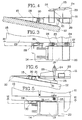
- the ramp according to the invention in the drawings designated 11, at one of its ends, the end 13 facing the quay 12, on one hand is elastically connected to two quay structures 14 and on the other hand is articulatedly connected to a flap 15.
- a floating element 17 At the end 16 of the ramp facing away from the quay is provided a floating element 17, which via a stand 18 supports the foremost end of the ramp.
- the floating element 17 may be trimmed with a suitable ballast for level adjustment of the ramp 11.
- the quay structures 14, which are firmly connected to the quay 12, are equipped with heavy energy absorbing shock absorbers 19, e.g. made from a rubber material, which in turn are connected to transverse beams 20 attached to the ramp 11.
- the shock absorbers 19 may be arranged beside the ramp or below the same.
- the flap 15 is articulatedly connected to the ramp 11 via a pivot 21.
- attachments 24 for a hydraulic actuator 25 are provided beside the carriage-way 22 on the ramp at longitudinal side beams 23 on the ramp, the opposite end of said actuator being connected to an attachment 26 provided on the flap 15.
- the flap 15, which is wedge-shaped, is loosely arranged upon the quay 12, thus that it may make the movements caused by sea and by the forces to which the ramp is subjected during landing of the ferry.
- the flap In order to prevent the flap 15 from being lifted from the quay 12, the flap cooperates with guides 28 firmly connected to the quay in parallel with the side edges 29 of the flap 15, force absorbing members 30, preferably in form of sliding blocks, rollers or the like being provided on said guides.
- the floating element 17 is provided at such a depth, that the water swell does not influence it or has only an insignificant influence thereon.
- the ramp 11 and its floating element 17 are furthermore so balanced that only comparatively weak actuators 25 are required for lifting the free front end of the ramp so much, that the attachment console of the ferry (not shown) can be moved below the raised ramp, which is thereupon lowered towards the ferry.
- the fixed guides 28 on both sides of the flap 15 prevent the flap from lifting when the ramp is swung upwards about the pivot 21, but at the same time it makes it possible for the ramp 11 and the flap 15 to make the horizontal movements occuring at swell and when the ferry is landing.
- each one of the hydralic actuators 25 is directed mainly vertically downward from the attachment 24 of the ramp towards one beam 31 each, which beams form an extension of the flap which is parallel to the ramp.
- the ramp 11 is swung upwardly, the front part of the flap, i.e. mainly the beams 31, will press against the quay 12, whereas the flap 15 is prevented from raising from the quay due to its cooperation with the guides 28.
- the energy absorbing members 19 can be positioned at a distance from each other, thus that the force couple created makes it possible to refrain from additional side anchoring of the ramp.
Landscapes
- Engineering & Computer Science (AREA)
- Mechanical Engineering (AREA)
- Architecture (AREA)
- Civil Engineering (AREA)
- Structural Engineering (AREA)
- Bridges Or Land Bridges (AREA)
- Auxiliary Methods And Devices For Loading And Unloading (AREA)
- Vending Machines For Individual Products (AREA)
- Transition And Organic Metals Composition Catalysts For Addition Polymerization (AREA)
Abstract
Claims (5)
- Ponton (11) pour poste d'amarrage de bateaux ferry ou analogues, dont l'une des extrémités (13) est reliée de manière élastique à une structure de quai (14) et dont l'extrémité opposée (16), qui est réglable verticalement par rapport à la surface de l'eau (27), repose sur un élément flottant (17), ponton qui, en outre, est relié, du côté du quai, à un volet (15) de manière pivotante, caractérisé en ce que le volet (15) repose, dans la direction longitudinale du ponton, dans des glissières de guidage (28) reliées fixement à la structure de quai (14) de manière à pouvoir être déplacé de façon linéaire, et en ce qu'à une certaine distance du pivot (21) commun au ponton (11) et au volet (15) est prévu, sur le ponton (11) et sur le volet (15), au moins un vérin (25) destiné à faire pivoter la rampe d'accès des véhicules par rapport au volet sur ledit pivot.
- Ponton selon la revendication 1, caractérisé en ce que le volet (15) peut être déplacé le long d'un plan (32) incliné en direction de la surface de l'eau (27).
- Ponton selon la revendication 1, caractérisé en ce que le volet (15) est muni d'au moins une paire d'éléments coulissants (30), par exemple sous forme de galets, qui sont prévus pour coopérer avec les glissières de guidage (28).
- Ponton selon la revendication 1, caractérisé en ce que des absorbeurs d'énergie (19) sont prévus sur les structures de quai (14) espacées à l'extérieur du ponton.
- Ponton selon la revendication 1, caractérisé en ce que plusieurs pontons (11) sont reliés dans une disposition parallèle pour former un poste d'amarrage pour plusieurs bateaux ferry.
Applications Claiming Priority (2)
| Application Number | Priority Date | Filing Date | Title |
|---|---|---|---|
| NO882326A NO164185C (no) | 1988-05-26 | 1988-05-26 | Kjoererampe for fergeleie e.l. |
| NO882326 | 1988-05-26 |
Publications (2)
| Publication Number | Publication Date |
|---|---|
| EP0448561A1 EP0448561A1 (fr) | 1991-10-02 |
| EP0448561B1 true EP0448561B1 (fr) | 1993-04-28 |
Family
ID=19890916
Family Applications (1)
| Application Number | Title | Priority Date | Filing Date |
|---|---|---|---|
| EP89906848A Expired - Lifetime EP0448561B1 (fr) | 1988-05-26 | 1989-05-25 | Ponton pour bateaux ferry et analogues |
Country Status (3)
| Country | Link |
|---|---|
| EP (1) | EP0448561B1 (fr) |
| NO (1) | NO164185C (fr) |
| WO (1) | WO1989011564A1 (fr) |
Families Citing this family (3)
| Publication number | Priority date | Publication date | Assignee | Title |
|---|---|---|---|---|
| GB9108618D0 (en) * | 1991-04-23 | 1991-06-12 | Arnprior Holdings Limited | Bridges for providing access from a water-borne craft to the shore |
| US7461611B2 (en) | 2006-09-28 | 2008-12-09 | Raymond Howard Hebden | Floating pontoon berthing facility for ferries and ships |
| NO345699B1 (no) * | 2018-06-20 | 2021-06-21 | Coast Innovation As | Flytende fergekaibro |
Family Cites Families (5)
| Publication number | Priority date | Publication date | Assignee | Title |
|---|---|---|---|---|
| FR2394642A1 (fr) * | 1977-03-22 | 1979-01-12 | Mac Gregor Comarain Sa | Rampe portuaire d'acces a un navire roulier |
| DE3104361C2 (de) * | 1981-02-07 | 1983-01-20 | Eisenwerke Kaiserslautern Entwicklungsgesellschaft mbH, 6750 Kaiserslautern | Vorrichtung zum Verstellen von Rampen an Fähren, Schwimmbrücken o.dgl. |
| SE451373B (sv) * | 1986-01-22 | 1987-10-05 | Macgregor Navire Int Ab | Korbar ramp for lastning och lossning av fartyg |
| SE456338B (sv) * | 1986-05-05 | 1988-09-26 | Macgregor Navire Int Ab | Dempanordning vid en pontonforsedd last- och lossningsramp |
| NO161747C (no) * | 1987-03-30 | 1989-09-20 | Tore Ivarsson | Landingsbrygge. |
-
1988
- 1988-05-26 NO NO882326A patent/NO164185C/no not_active IP Right Cessation
-
1989
- 1989-05-25 EP EP89906848A patent/EP0448561B1/fr not_active Expired - Lifetime
- 1989-05-25 WO PCT/SE1989/000297 patent/WO1989011564A1/fr active IP Right Grant
Also Published As
| Publication number | Publication date |
|---|---|
| NO164185B (no) | 1990-05-28 |
| NO164185C (no) | 1990-09-05 |
| EP0448561A1 (fr) | 1991-10-02 |
| WO1989011564A1 (fr) | 1989-11-30 |
| NO882326D0 (no) | 1988-05-26 |
| NO882326L (no) | 1989-11-27 |
Similar Documents
| Publication | Publication Date | Title |
|---|---|---|
| US6293734B1 (en) | Apparatus for transporting and installing a deck of an offshore oil production platform | |
| US8286574B2 (en) | Lowerable platform with float for a watercraft | |
| US3541987A (en) | Water vehicle with elevated deck | |
| US4441449A (en) | Port ramp for access to a roll-on roll-off ship | |
| GB2165188A (en) | Installation and removal vessel | |
| WO1990003470A3 (fr) | Procede et appareil de construction et de demontage de structures en haute mer | |
| EP0448561B1 (fr) | Ponton pour bateaux ferry et analogues | |
| EP1304415A1 (fr) | Guidage pour pilotis | |
| GB2156758A (en) | Semi-submersible crane vessel | |
| US5806455A (en) | Trim adjusting device for planing hull | |
| US4337545A (en) | Bridges for providing access from a water-borne craft to the shore | |
| WO1988007605A1 (fr) | Rampe de chargement | |
| US4831751A (en) | Water craft for clearing navigational waters | |
| NL8801920A (nl) | Werkwijze voor het door middel van een half-afzinkbaar vaartuig zoals een dokschip transporteren van een zware last, en een inrichting voor het uitvoeren van de werkwijze. | |
| CN110593191B (zh) | 自适应水位变化的浮码头活动钢引桥楼梯踏步调平系统 | |
| EP0132013B1 (fr) | Tin pour le soutènement d'un navire dans un dock | |
| GB2111449A (en) | Passenger bridge | |
| GB2047175A (en) | Mobile caisson structure | |
| SU1693169A1 (ru) | Временный инвентарный причал | |
| KR102181192B1 (ko) | 공기 부양식 보트 리프트 장치 | |
| JPS605084Y2 (ja) | 自己上昇式作業台の固定装置 | |
| JPS6226309Y2 (fr) | ||
| SU1686060A1 (ru) | Временный инвентарный причал | |
| CA2168444C (fr) | Dispositif d'amarrage d'une embarcation a un point d'accostage | |
| JPS5847075Y2 (ja) | ジヤッキアップリグの曳航時における脚に対する衝撃の軽減構造 |
Legal Events
| Date | Code | Title | Description |
|---|---|---|---|
| PUAI | Public reference made under article 153(3) epc to a published international application that has entered the european phase |
Free format text: ORIGINAL CODE: 0009012 |
|
| 17P | Request for examination filed |
Effective date: 19901120 |
|
| AK | Designated contracting states |
Kind code of ref document: A1 Designated state(s): BE DE FR GB IT NL SE |
|
| 17Q | First examination report despatched |
Effective date: 19921008 |
|
| GRAA | (expected) grant |
Free format text: ORIGINAL CODE: 0009210 |
|
| AK | Designated contracting states |
Kind code of ref document: B1 Designated state(s): BE DE FR GB IT NL SE |
|
| PG25 | Lapsed in a contracting state [announced via postgrant information from national office to epo] |
Ref country code: IT Free format text: LAPSE BECAUSE OF FAILURE TO SUBMIT A TRANSLATION OF THE DESCRIPTION OR TO PAY THE FEE WITHIN THE PRESCRIBED TIME-LIMIT;WARNING: LAPSES OF ITALIAN PATENTS WITH EFFECTIVE DATE BEFORE 2007 MAY HAVE OCCURRED AT ANY TIME BEFORE 2007. THE CORRECT EFFECTIVE DATE MAY BE DIFFERENT FROM THE ONE RECORDED. Effective date: 19930428 |
|
| REF | Corresponds to: |
Ref document number: 68906268 Country of ref document: DE Date of ref document: 19930603 |
|
| ET | Fr: translation filed | ||
| PLBE | No opposition filed within time limit |
Free format text: ORIGINAL CODE: 0009261 |
|
| STAA | Information on the status of an ep patent application or granted ep patent |
Free format text: STATUS: NO OPPOSITION FILED WITHIN TIME LIMIT |
|
| 26N | No opposition filed | ||
| EAL | Se: european patent in force in sweden |
Ref document number: 89906848.0 |
|
| PGFP | Annual fee paid to national office [announced via postgrant information from national office to epo] |
Ref country code: BE Payment date: 19970514 Year of fee payment: 9 Ref country code: FR Payment date: 19970514 Year of fee payment: 9 Ref country code: GB Payment date: 19970514 Year of fee payment: 9 |
|
| PGFP | Annual fee paid to national office [announced via postgrant information from national office to epo] |
Ref country code: NL Payment date: 19970516 Year of fee payment: 9 |
|
| PGFP | Annual fee paid to national office [announced via postgrant information from national office to epo] |
Ref country code: DE Payment date: 19970530 Year of fee payment: 9 |
|
| PG25 | Lapsed in a contracting state [announced via postgrant information from national office to epo] |
Ref country code: GB Free format text: LAPSE BECAUSE OF NON-PAYMENT OF DUE FEES Effective date: 19980525 |
|
| PG25 | Lapsed in a contracting state [announced via postgrant information from national office to epo] |
Ref country code: BE Free format text: LAPSE BECAUSE OF NON-PAYMENT OF DUE FEES Effective date: 19980531 Ref country code: FR Free format text: LAPSE BECAUSE OF NON-PAYMENT OF DUE FEES Effective date: 19980531 |
|
| BERE | Be: lapsed |
Owner name: IVARSSON TORE Effective date: 19980531 |
|
| PG25 | Lapsed in a contracting state [announced via postgrant information from national office to epo] |
Ref country code: NL Free format text: LAPSE BECAUSE OF NON-PAYMENT OF DUE FEES Effective date: 19981201 |
|
| GBPC | Gb: european patent ceased through non-payment of renewal fee |
Effective date: 19980525 |
|
| NLV4 | Nl: lapsed or anulled due to non-payment of the annual fee |
Effective date: 19981201 |
|
| PG25 | Lapsed in a contracting state [announced via postgrant information from national office to epo] |
Ref country code: DE Free format text: LAPSE BECAUSE OF NON-PAYMENT OF DUE FEES Effective date: 19990302 |
|
| REG | Reference to a national code |
Ref country code: FR Ref legal event code: ST |
|
| PGFP | Annual fee paid to national office [announced via postgrant information from national office to epo] |
Ref country code: SE Payment date: 20080520 Year of fee payment: 20 |
|
| EUG | Se: european patent has lapsed |