EP0448447A1 - Verfahren und Vorrichtung zum Biegen von Glasscheiben - Google Patents
Verfahren und Vorrichtung zum Biegen von Glasscheiben Download PDFInfo
- Publication number
- EP0448447A1 EP0448447A1 EP91400691A EP91400691A EP0448447A1 EP 0448447 A1 EP0448447 A1 EP 0448447A1 EP 91400691 A EP91400691 A EP 91400691A EP 91400691 A EP91400691 A EP 91400691A EP 0448447 A1 EP0448447 A1 EP 0448447A1
- Authority
- EP
- European Patent Office
- Prior art keywords
- bending
- frame
- sheets
- pivoting
- glass sheet
- Prior art date
- Legal status (The legal status is an assumption and is not a legal conclusion. Google has not performed a legal analysis and makes no representation as to the accuracy of the status listed.)
- Granted
Links
Images


Classifications
-
- C—CHEMISTRY; METALLURGY
- C03—GLASS; MINERAL OR SLAG WOOL
- C03B—MANUFACTURE, SHAPING, OR SUPPLEMENTARY PROCESSES
- C03B23/00—Re-forming shaped glass
- C03B23/02—Re-forming glass sheets
- C03B23/023—Re-forming glass sheets by bending
- C03B23/025—Re-forming glass sheets by bending by gravity
- C03B23/027—Re-forming glass sheets by bending by gravity with moulds having at least two upward pivotable mould sections
Definitions
- the present invention relates to the bending or bending of glass sheets and in particular the bending on a bending form or hollowed out configuration commonly designated by bending frame or skeleton.
- the bending of glass sheets onto a skeleton is a technique commonly used for bending the glass sheets and in particular for simultaneously bending the two glass sheets intended to form a curved laminated glazing such as a transport vehicle windshield.
- the two glass sheets placed one on the other with the interposition of a suitable separation agent are supported along their marginal end portions in a substantially horizontal manner by a frame having the desired profile. , that is to say the profile corresponding to that of the final two curved glass sheets.
- the two glass sheets pass through a bending oven, generally an oven having zones of different temperatures.
- the first of these zones is a preheating zone in which the glass sheets are heated to a temperature of the glass substantially close to the softening point.
- the next area is the bending area where the glass sheets brought to a temperature of about 600 ° C will gradually bend by gravity to finally match the shape of the frame.
- the glass sheets are then cooled to be taken out of the tunnel furnace, removed from the forming frame.
- the curved glass sheets obtained then no longer meet the conditions imposed on the glazing in order to be able to be mounted in a body bay.
- the invention provides a method and a device which aims to overcome the aforementioned drawbacks, making it possible to eliminate the counter-bending, in particular during the bending of two sheets of glass simultaneously.
- the invention overcomes the disadvantages mentioned. It proposes a new method of bending by gravity of one or more sheets of glass simultaneously, making it possible to eliminate the counter-bending, which leaves no mark on the visible part of the sheet or sheets of glass and which also allows good homogenization of the temperature of the glass sheets after the bending proper.
- the method of bending by gravity according to the invention comprises at least two steps for the bending proper during which the glass sheet or sheets undergo a modification of their shape by gravity by being supported on the periphery, a first step during which the glass sheet or sheets are bent by gravity in a first shape corresponding to a rough form of the final shape, then a second step during which the glass sheet or sheets are bent by gravity according to the final form.
- the first bending step providing the shape of a blank consists in bending essentially according to a first curvature generally corresponding to the transverse curvature of the glass sheet or sheets, without significant modification of the second curvature then corresponding to the longitudinal curvature of the glass sheet (s), and the second step consists in finishing the first curvature and essentially producing the second curvature.
- the first bending step consists in bending essentially along the transverse curvature and according to the longitudinal curvature localized for the latter at the middle part of the sheet or sheets of glass
- the second step of bending consists of a complementary bending which is essentially longitudinal and located on the peripheral parts of the glass sheet or sheets.
- the first bending step is carried out by supporting the glass sheet or sheets along a first peripheral line which may, if necessary, vary during the first step, and the second is carried out bending step by supporting the glass sheet or sheets along a second peripheral line of different curvature which replaces the first.
- the two peripheral lines are entirely separate from each other, one being arranged inside the other.
- the substitution of one line by the other takes place either by raising the level of the second line relative to the level of the first, or by lowering the level of this first line.
- this second peripheral line is distinct in parts only from the first line.
- the distinction or difference may relate to the lateral parts of the two lines.
- the difference generally consists in that the lateral parts of the second line have more accentuated curvatures and are placed at a level higher than the level of the lateral parts of the first line.
- peripheral lines according to the invention are generally continuous lines in particular for the line defining the final curved shape of the glass sheet or sheets, although a line formed by several points arranged in suitable locations may also be suitable, in particular for the line defining the blank.
- the first peripheral line intended for carrying out the first bending step is such that the angle formed by any vector tangent to said line with the horizontal plane is less than 20 degrees and preferably less than 15 degrees.
- the invention also relates to a device for the bending by gravity of one or more stacked glass sheets and in particular a new bending frame.
- the bending frame according to the invention comprises a peripheral strip at least part of which is lined with two elements, one element forming a so-called blank frame and being used to support the periphery of the sheet or sheets of glass to be bent during the first bending step consisting in forming a shape blank, and a second element forming a so-called definitive frame replacing the first and being used to support the periphery of the glass sheet or sheets during the second bending step to arrive at the final shape .
- the doubled part can extend over the entire periphery of the frame.
- the doubled part is limited to the two lateral parts of the frame.
- the device in one embodiment, consists of a fixed blank frame on which are articulated, at the desired locations, in particular on the two lateral parts, pivoting elements which can occupy two positions, a so-called position rest, eclipsed, these pivoting elements being arranged at a level lower than the lateral parts of the fixed frame, and a so-called working position, when these elements replace the fixed lateral parts for supporting the sheets to be bent along a peripheral line located at a level higher than the level of the fixed lateral parts, thus forming a definitive frame.
- Means allowing the pivoting of the pivoting elements are provided. These means can be a weight system kept locked in a position and that is unlocked at the desired time, or any other suitable system, in particular a system using the weight of the frame itself.
- the blank frame has a pivoting part which in the working position is arranged at a level higher than that of the fixed final frame in this variant, and which in the rest position is lowered to a level lower than that of the active part of the final frame.
- the blank frame and the final frame both have pivoting parts.
- the blank frame may have pivoting parts which pivot as the blank is formed.
- the first peripheral bending line which has previously been defined according to the invention as being the line of the support of the glass sheet or sheets for the formation of the blank is a line whose shape varies as and as the blank is formed.
- the pivoting parts of the blank frame are the lateral parts which then carry the pivoting lateral crosspieces intended to form the final frame.
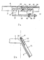
- Figure 1 shows an embodiment of a bending device or frame in a perspective view.
- FIGS. 2a and 2b represent the mounting of the pivoting part of the frame shown in FIG. 1.
- Figure 3 schematically shows the arrangement of the bending frame of Figure 1 during the first bending step.
- Figure 4 schematically shows the arrangement of the bending frame of Figure 1 during the second bending step.
- FIG. 5 schematically represents an embodiment of a device which can be used for the bending of a glazing subject to counter-bending near its four corners.
- Figure 6 schematically shows the configuration of the bending device of Figure 5, adopted during the second bending step.
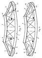
- Figures 7a, 7b and 7c schematically represent the evolution of the bending of a glass sheet on a standard known bending frame.
- Figures 8a, 8b, 8c schematically show the development of bending of a glass sheet on a bending frame according to the invention.
- FIG. 9 schematically represents a variant of a device which can be used for bending a glazing unit subject to counter-bending near its four corners.
- Figure 10 schematically shows the device of Figure 9 in its configuration corresponding to the second bending step.
- the device shown in FIG. 1 comprises a fixed frame 1 arranged horizontally, comprising two longitudinal parts or longitudinal members 2,3 and two transverse parts or end crossmembers 4,5.
- the spar 2 shown here has a relatively accentuated line of curvature (in projection in the horizontal plane), which corresponds to a cutting of glazing particularly suitable for counter-bending near the two lower corners.
- the upper edge 6 of the fixed frame constitutes the bending line which corresponds to the shape of the blank for the sheets of glass to be bent.
- This fixed frame is the rough frame.
- the side members 2.3 and the cross members 4.5 are connected by spacers 7 which ensure the rigidity of the system.
- the two longitudinal members 2,3 carry near their ends, as described below, essentially horizontal axes 8, 9, 10, 11 (the axes 8 and 9 being aligned here, the same for the two axes 10 and 11) around which are hinged mounted, two pivoting crosspieces 12, 13 which have a profile corresponding to the final profile desired for the lateral parts of the sheets to be bent.
- An assembly of a pivoting cross member is shown in FIGS. 2a and 2b commented on below.
- the two pivoting crosspieces 12, 13 are each formed of a transverse part 14, 15 relative to the frame and of a wing 16, 17, which joins the spar 2.
- the curvatures of these pivoting crosspieces 12, 13 correspond to the final bending profile as described below. These curvatures are therefore more pronounced than the curvatures of the fixed crosspieces of the frame.
- the two pivoting crosspieces 12, 13 can occupy two positions as shown schematically in Figures 3 and 4.
- a first position which is that shown here in Figures 1 and 3 is the so-called rest position, or overshadowed relative to the fixed frame 1 , in particular with respect to the fixed side rails 4,5 of this frame.
- the second position shown in Figure 4 is the working position.
- the profile of the upper edge of the pivoting crosspieces 12, 13 regularly extends the upper edge of the side members 2, 3 along a curve tangent to the curve of these side members 2, 3, the assembly forming the bending line. final device.
- Two rails 18, 19 are provided under the fixed frame allowing the mounting of the bending frame on a carriage, not shown, which in a known manner conveys the frame in the bending oven.
- the mounting of the pivoting crosspieces is designed in such a way that the pivoting crosspieces come to double the fixed crosspieces in the closest possible way, so that the peripheral contact line between these pivoting crosspieces and the glass sheet is closest to the line of contact between the fixed crosspieces and said glass sheet.
- FIG 2a there is shown a detail of the mounting of the wing 17 of a pivoting cross member 13 on the front spar 2 of the fixed frame 1.
- the fixed frame provided with a reinforcement 29 bears integrally at the end of two rods 30 , a plate 31 having an arm 32, the end of which carries an axis 10 around which another plate 33 can pivot, held by two rods 34 fixed on the wing 17 of the pivoting cross member 13.
- the pivot axis 10 is located at level of the upper edge 6 of the fixed frame.
- the plate 31 also carries a threaded rod 35 on which are arranged two nuts 36, 37 at the appropriate locations which delimit the amplitude of the pivoting movement of the cross member in cooperation with a stop 38 carried by the plate 33 secured to the pivoting cross member.
- FIG. 2b there is shown the mounting of the cross member on the rear spar 3 of the fixed frame 1.
- the end of the spar carries an axis 11 around which is rotatably mounted a bore 39 integral with the pivoting cross member 13 via d '' a square 40 and a plate 41.
- This device is used for bending two sheets of glass intended to be used to manufacture laminated glazings, for example a windshield of a motor vehicle.
- the curved glazing to be manufactured is such that when placed in a horizontal position, a vector tangent to the lateral end of the widest part of the glazing forms an angle of about 45 degrees with the horizontal plane.
- the device is in its configuration in which the pivoting crosspieces are in the eclipsed position in accordance with FIG. 3.
- the maintenance of this position is ensured by the jumper 26 which connects the two rods 24, 25.
- the two glass sheets are placed on the frame being centered for example by means of knobs (not shown) arranged around the periphery of the frame.
- the lower glass sheet (not shown) bears at various points on the frame about 5 mm from its edge.
- the angle formed by a vector tangent to the upper edge of the fixed frame with a horizontal plane is about 15 degrees.
- the device is then brought into the bending oven.
- a first phase the assembly undergoes preheating.
- a second phase which carries and maintains the glass at a temperature of around 600 ° C.
- the glass sheets collapse by gravity and bear on the periphery of the fixed frame mainly on the central parts of the side members 2, 3, thus taking the form of a blank of the final curvatures to be obtained.
- This blank shape has in particular a transverse curvature close to the definitive transverse curvature.
- This action causes the pivoting of the two pivoting crosspieces 12, 13 which during this movement replace the two fixed lateral parts 4, 5 for supporting the glass sheets along a very close peripheral line and offset externally from the first peripheral line formed by the fixed lateral parts, of the distance that one chooses preferably minimum.
- This minimum distance generally corresponds to the thickness of the pivoting crosspieces increased by the clearance necessary for the very close doubling of the pivoting crosspieces of the fixed crosspieces.
- the two peripheral support lines for the transverse parts are thus very close together and both very close to the edge of the bottom sheet.
- the two close peripheral marks can thus be in the area covered by the seal used for mounting the glazing in the bodywork bay and are therefore invisible on the glazing fitted.
- the device When the two pivoting parts replace the fixed parts as peripheral support for the glass sheets, the device is then in the configuration shown in FIG. 4.
- the wings 16, 17 of the pivoting parts thus extend the central parts of the two longitudinal members 2, 3 along a regular line corresponding to the final curvature desired for the glass sheets.
- the central area of the pivoting parts has the curvature definitive transverse which is more accentuated than the curvature presented by the fixed crosspieces of the frame.
- the assembly is subjected to a homogenization of the temperatures and then the device is removed from the bending oven.
- the two glass sheets are removed from the bending frame and they can be used for the manufacture of laminated glazing by interposing between them an interlayer sheet of polyvinyl butyral for example.
- FIGs 5 and 6 there is shown a device which can be used for bending a glazing subject to counter-bending near its four corners.
- This device essentially comprises the same elements as that described above, except as regards its lateral parts.
- the device comprises a fixed frame 42 formed of two longitudinal members 43, 44 and two end crossmembers 45, 46.
- Its pivoting crossmembers 47, 48 each have here two wings 49, 50, 51, 52 which are pivotally mounted around horizontal axes 53, 54, 55, 56 as in the previous device for mounting the pivoting crosspieces 12, 13 on the front spar 2.
- this device is similar to that described above.
- the glass sheet or sheets are placed horizontally on the fixed frame while the device is in position according to FIG. 5.
- the first bending step providing the blank shape takes place on the fixed frame.
- the second bending step providing the final shape takes place while the device is in the configuration according to FIG. 6.
- the transition from one configuration to another is carried out as before by the action of weights 22, 23 and d '' a locking and unlocking system with rods and jumper (not shown).
- the angle formed by the horizontal plane which is that of the glass sheet and the frame in the lower left corner is about 35 degrees.
- the glass sheet 60 As shown in FIG. 7a, there is a slight counter-bending along the line 61.
- the glass sheet curves and the counter-bending along line 61 is accentuated.
- the glass sheet presents a definitive bending with a pronounced counter-bending according to FIG. 61.
- the angle formed by the glass sheet 60 that is to say the horizontal plane, and the fixed frame in the lower corner left, is around 15 degrees.
- the glass is supported on the fixed frame and there appears a positive curvature according to the line 63.
- the glass is curved and there is no counter-bending.
- the curvature is positive along line 63.
- FIGS. 9 and 10 a variant of a frame has been shown for the bending of a glazing unit subject to counter-bending near its four corners.
- the frame here incorporates the essential characteristics of the frame described in relation to FIGS. 5 and 6. It includes a fixed frame 64 formed of two longitudinal members 65, 66 and two end crossmembers 67, 68, as well as two pivoting crossmembers 69, 70, each have two wings 71, 72, 73, 74, pivotally mounted around the four axes aligned two by two along the lines of axes 75, 76, carried by the fixed frame at a level corresponding to that of the edge upper part of this frame.
- the device differs from the previous frame by the means causing the pivoting crosspieces 69, 70 to tilt.
- the mounting of the frame on the carriage intended to convey the frame in the bending oven is carried out here by means of two round bars 77, 78 extending transversely and mounted freely rotating at their ends in holes 79 provided in plates 80 surmounted by hooks 81 allowing the frame to be hooked on the carriage (not shown).
- the frame is connected to the two bars 77, 78 by means of arms 82 mounted on rings 83 which can pivot around the bars 77, 78.
- the arms 82 are fixed to the wings of the pivoting crosspieces.
- the bending frame is then in the position shown in FIG. 10.
- it is therefore the weight of the frame and not of the weights which causes the pivoting, at the desired moment, of the pivoting crosspieces for the passage of the configuration draft frame to final frame configuration.
- the method and the device according to the invention advantageously apply to the bending by gravity of glass sheets subject to a counter-bending.
Applications Claiming Priority (2)
| Application Number | Priority Date | Filing Date | Title |
|---|---|---|---|
| FR9003513A FR2659957B1 (fr) | 1990-03-20 | 1990-03-20 | Procede et dispositif pour le bombage de feuilles de verre. |
| FR9003513 | 1990-03-20 |
Publications (2)
| Publication Number | Publication Date |
|---|---|
| EP0448447A1 true EP0448447A1 (de) | 1991-09-25 |
| EP0448447B1 EP0448447B1 (de) | 1995-01-25 |
Family
ID=9394894
Family Applications (1)
| Application Number | Title | Priority Date | Filing Date |
|---|---|---|---|
| EP91400691A Expired - Lifetime EP0448447B1 (de) | 1990-03-20 | 1991-03-14 | Verfahren und Vorrichtung zum Biegen von Glasscheiben |
Country Status (5)
| Country | Link |
|---|---|
| US (1) | US5167689A (de) |
| EP (1) | EP0448447B1 (de) |
| DE (1) | DE69106912T2 (de) |
| ES (1) | ES2068528T3 (de) |
| FR (1) | FR2659957B1 (de) |
Cited By (14)
| Publication number | Priority date | Publication date | Assignee | Title |
|---|---|---|---|---|
| EP0705798A1 (de) | 1994-10-04 | 1996-04-10 | Saint-Gobain Vitrage | Verfahren und Vorrichtung zum Biegen von Glasscheiben |
| JP2002308635A (ja) * | 2001-04-10 | 2002-10-23 | Asahi Glass Co Ltd | ガラス板曲げ成形装置および成形方法 |
| WO2010136702A1 (fr) | 2009-05-27 | 2010-12-02 | Saint-Gobain Glass France | Vitrage a faible niveau de double image |
| WO2012022904A1 (fr) | 2010-08-20 | 2012-02-23 | Saint-Gobain Glass France | Miroir bombe par pressage |
| WO2012049433A1 (fr) | 2010-10-15 | 2012-04-19 | Saint-Gobain Glass France | Procede de bombage et support de trempe thermique |
| WO2017178733A1 (fr) | 2016-04-13 | 2017-10-19 | Saint-Gobain Glass France | Bombage de feuilles de verre |
| BE1024134B1 (fr) * | 2016-05-19 | 2017-11-17 | Mechanical Glass Center | Structure pour le contrôle de vitrages bombés |
| WO2018020087A1 (fr) | 2016-07-25 | 2018-02-01 | Saint-Gobain Glass France | Support de verre a aspiration |
| WO2019077277A1 (fr) | 2017-10-19 | 2019-04-25 | Saint-Gobain Glass France | Bombage de verre par gravite entre squelette et contre-squelette |
| WO2019081317A1 (de) | 2017-10-27 | 2019-05-02 | Saint-Gobain Glass France | Mittel zur immobilisierung einer scheibe |
| WO2019129980A1 (fr) | 2017-12-29 | 2019-07-04 | Saint-Gobain Glass France | Procede de bonbage de feuille de verre |
| US10343378B2 (en) | 2013-10-23 | 2019-07-09 | Saint-Gobain Glass France | Thin laminated glass for windscreen |
| WO2019202242A1 (fr) | 2018-04-16 | 2019-10-24 | Saint-Gobain Glass France | Support de bombage gravitaire du verre |
| WO2020174185A1 (fr) | 2019-02-28 | 2020-09-03 | Saint-Gobain Glass France | Fabrication de vitrages a contrainte d'extension reduite |
Families Citing this family (21)
| Publication number | Priority date | Publication date | Assignee | Title |
|---|---|---|---|---|
| FR2709483B1 (fr) * | 1993-08-31 | 1995-10-20 | Saint Gobain Vitrage Int | Procédé et dispositif pour le bombage de feuilles de verre. |
| US5882370A (en) * | 1995-06-07 | 1999-03-16 | Pilkington Glass Limited | Method of bending glass sheets |
| US5645621A (en) * | 1995-06-07 | 1997-07-08 | Pilkington Glass Limited | Apparatus for and method of bending glass sheets |
| GB9511556D0 (en) * | 1995-06-07 | 1995-08-02 | Triplex Safety Glass Co | Apparatus for and method of bending glass sheets |
| GB9511545D0 (en) * | 1995-06-07 | 1995-08-02 | Triplex Safety Glass Co | Apparatus for and method of bending glass sheets |
| US6076373A (en) * | 1997-06-16 | 2000-06-20 | Ppg Industries Ohio, Inc. | Apparatus and method for bending glass sheets |
| JPH11157857A (ja) * | 1997-11-19 | 1999-06-15 | Asahi Glass Co Ltd | ガラス板の曲げ成形方法および装置 |
| DE10105200A1 (de) | 2001-02-06 | 2002-08-14 | Saint Gobain | Verfahren und Vorrichtung zum paarweisen Biegen von Glasscheiben |
| FR2855168B1 (fr) * | 2003-05-19 | 2007-03-30 | Saint Gobain | Bombage de vitrages par gravite sur une multiplicite de supports |
| US20070005056A1 (en) * | 2005-06-30 | 2007-01-04 | Surginetics, Llc | Electrosurgical Instrument With Blade Profile For Reduced Tissue Damage |
| FR2894955B1 (fr) * | 2005-12-20 | 2008-05-02 | Saint Gobain | Dispositif de bombage de verre par gravite sur plusieurs formes de support a transition de forme controlee |
| GB0624190D0 (en) | 2006-12-04 | 2007-01-10 | Pilkington Glass Ltd | Gravity bending glass sheets |
| GB0624192D0 (en) | 2006-12-04 | 2007-01-10 | Pilkington Group Ltd | Gravity bending glass sheets |
| GB0724162D0 (en) | 2007-12-11 | 2008-01-23 | Pilkington Group Ltd | Gravity bending glass sheets |
| GB0810001D0 (en) | 2008-06-02 | 2008-07-09 | Pilkington Group Ltd | Gravity bending glass sheets |
| WO2013055861A1 (en) | 2011-10-13 | 2013-04-18 | Corning Incorporated | Thermo-mechanical reforming method and system and mechanical reforming tool |
| US8833106B2 (en) | 2012-09-18 | 2014-09-16 | Corning Incorporated | Thermo-mechanical reforming method and system and mechanical reforming tool |
| US8549885B2 (en) | 2011-11-23 | 2013-10-08 | Corning Incorporated | Process and system for precision glass sheet bending |
| FR2990430B1 (fr) | 2012-05-14 | 2018-05-18 | Helioclim | Procede de mise en forme d'une feuille de verre et miroir comportant une telle feuille de verre |
| FR3017865A1 (fr) * | 2014-02-27 | 2015-08-28 | Saint Gobain | Bombage par gravite sur double-support |
| CN104860513B (zh) * | 2015-04-15 | 2017-03-29 | 福耀玻璃工业集团股份有限公司 | 一种汽车玻璃热弯成型模具 |
Citations (2)
| Publication number | Priority date | Publication date | Assignee | Title |
|---|---|---|---|---|
| DE1100238B (de) * | 1958-11-06 | 1961-02-23 | Kinon Glas Spiegel | Vorrichtung zum Biegen von unterschiedlich gewoelbten Glasscheiben |
| GB2051037A (en) * | 1979-05-23 | 1981-01-14 | Nissan Motor | Method and apparatus for forming bent plate glass |
Family Cites Families (1)
| Publication number | Priority date | Publication date | Assignee | Title |
|---|---|---|---|---|
| US4074996A (en) * | 1976-07-28 | 1978-02-21 | Libbey-Owens-Ford Company | Method of and apparatus for bending glass sheets |
-
1990
- 1990-03-20 FR FR9003513A patent/FR2659957B1/fr not_active Expired - Fee Related
-
1991
- 1991-03-14 EP EP91400691A patent/EP0448447B1/de not_active Expired - Lifetime
- 1991-03-14 DE DE69106912T patent/DE69106912T2/de not_active Expired - Fee Related
- 1991-03-14 ES ES91400691T patent/ES2068528T3/es not_active Expired - Lifetime
- 1991-03-20 US US07/672,336 patent/US5167689A/en not_active Expired - Lifetime
Patent Citations (2)
| Publication number | Priority date | Publication date | Assignee | Title |
|---|---|---|---|---|
| DE1100238B (de) * | 1958-11-06 | 1961-02-23 | Kinon Glas Spiegel | Vorrichtung zum Biegen von unterschiedlich gewoelbten Glasscheiben |
| GB2051037A (en) * | 1979-05-23 | 1981-01-14 | Nissan Motor | Method and apparatus for forming bent plate glass |
Cited By (20)
| Publication number | Priority date | Publication date | Assignee | Title |
|---|---|---|---|---|
| EP0705798A1 (de) | 1994-10-04 | 1996-04-10 | Saint-Gobain Vitrage | Verfahren und Vorrichtung zum Biegen von Glasscheiben |
| JP2002308635A (ja) * | 2001-04-10 | 2002-10-23 | Asahi Glass Co Ltd | ガラス板曲げ成形装置および成形方法 |
| EP1380547A1 (de) † | 2001-04-10 | 2004-01-14 | Asahi Glass Company Ltd. | Verfahren und vorrichtung zum biegen einer glassplatte |
| EP1380547B2 (de) † | 2001-04-10 | 2012-10-24 | Asahi Glass Company, Limited | Verfahren und vorrichtung zum biegen einer glassplatte |
| WO2010136702A1 (fr) | 2009-05-27 | 2010-12-02 | Saint-Gobain Glass France | Vitrage a faible niveau de double image |
| WO2012022904A1 (fr) | 2010-08-20 | 2012-02-23 | Saint-Gobain Glass France | Miroir bombe par pressage |
| WO2012049433A1 (fr) | 2010-10-15 | 2012-04-19 | Saint-Gobain Glass France | Procede de bombage et support de trempe thermique |
| US10343378B2 (en) | 2013-10-23 | 2019-07-09 | Saint-Gobain Glass France | Thin laminated glass for windscreen |
| WO2017178733A1 (fr) | 2016-04-13 | 2017-10-19 | Saint-Gobain Glass France | Bombage de feuilles de verre |
| US11174188B2 (en) | 2016-04-13 | 2021-11-16 | Saint-Gobain Glass France | Bending of sheets of glass |
| BE1024134B1 (fr) * | 2016-05-19 | 2017-11-17 | Mechanical Glass Center | Structure pour le contrôle de vitrages bombés |
| WO2018020087A1 (fr) | 2016-07-25 | 2018-02-01 | Saint-Gobain Glass France | Support de verre a aspiration |
| WO2019077277A1 (fr) | 2017-10-19 | 2019-04-25 | Saint-Gobain Glass France | Bombage de verre par gravite entre squelette et contre-squelette |
| WO2019077278A1 (fr) | 2017-10-19 | 2019-04-25 | Saint-Gobain Glass France | Bombage de verre par gravite en presence d'un contre-squelette radiatif |
| WO2019081317A1 (de) | 2017-10-27 | 2019-05-02 | Saint-Gobain Glass France | Mittel zur immobilisierung einer scheibe |
| DE202018006733U1 (de) | 2017-10-27 | 2022-05-31 | Saint-Gobain Glass France | Mittel zur Immobilisierung einer Scheibe |
| WO2019129980A1 (fr) | 2017-12-29 | 2019-07-04 | Saint-Gobain Glass France | Procede de bonbage de feuille de verre |
| WO2019202242A1 (fr) | 2018-04-16 | 2019-10-24 | Saint-Gobain Glass France | Support de bombage gravitaire du verre |
| WO2020174185A1 (fr) | 2019-02-28 | 2020-09-03 | Saint-Gobain Glass France | Fabrication de vitrages a contrainte d'extension reduite |
| FR3093333A1 (fr) | 2019-02-28 | 2020-09-04 | Saint-Gobain Glass France | Fabrication de vitrages a contrainte d’extension reduite |
Also Published As
| Publication number | Publication date |
|---|---|
| EP0448447B1 (de) | 1995-01-25 |
| ES2068528T3 (es) | 1995-04-16 |
| US5167689A (en) | 1992-12-01 |
| DE69106912D1 (de) | 1995-03-09 |
| FR2659957A1 (fr) | 1991-09-27 |
| FR2659957B1 (fr) | 1993-07-16 |
| DE69106912T2 (de) | 1995-08-03 |
Similar Documents
| Publication | Publication Date | Title |
|---|---|---|
| EP0448447B1 (de) | Verfahren und Vorrichtung zum Biegen von Glasscheiben | |
| EP0640569B1 (de) | Verfahren und Vorrichtung zum Biegen von Glasscheiben | |
| EP0023466B1 (de) | Ausklappbare Struktur für ein an das Dach eines Kraftfahrzeuges anpassbares Dachzelt | |
| EP0041411B1 (de) | Umwandelbarer Fahrzeugsitz mit schwenkbarem Sitzkissen und umklappbarer Rückenlehne, die gleichzeitig beweglich sind | |
| EP3697733A1 (de) | Schwerkraftbiegen von glas zwischen einem rahmen und einem gegenrahmen | |
| EP0240418B1 (de) | Verfahren und Vorrichtung zum Formen von Glas | |
| FR2624848A1 (fr) | Procede et appareillage pour profiler une feuille de verre a un contour desire, notamment des glaces pour automobiles | |
| EP3110767B1 (de) | Schwerkraftbiegung auf doppelhalterung | |
| EP0614429B1 (de) | Verfahren zum herstellen von transportwagen aus kunststoff | |
| FR2745244A1 (fr) | Vehicule automobile equipe d'une banquette arriere deplacable et transformable | |
| BE620670A (de) | ||
| FR2651771A1 (fr) | Dispositif pour donner un profil desire a une feuille de verre, et procede de mise en óoeuvre du dispositif. | |
| EP3068553B1 (de) | Walzwerk mit mehreren walzen und einer luke | |
| FR2876637A1 (fr) | Cloison de separation amovible pour vehicule utilitaire, vehicule utilitaire equipe d'une telle cloison | |
| FR3044951A1 (fr) | Presse de cuisson d'une ebauche de pneumatique comprenant une biellette | |
| EP0389323B1 (de) | Vorrichtung zum Biegen und Härten einer Glasscheibe | |
| FR2928125A1 (fr) | Wagon de manutention de charges lourdes, notamment de rails, et utilisation d'un tel wagon en presence d'une catenaire | |
| EP0250311B1 (de) | Verfahren und Vorrichtung zum Biegen von Glasplatten | |
| FR2851982A1 (fr) | Potence de suspension, et conteneur de pieces equipe d'au moins une telle potence de suspension | |
| WO2019202242A1 (fr) | Support de bombage gravitaire du verre | |
| FR2613710A1 (fr) | Appareil pour la fabrication de feuilles de verre cintrees | |
| FR3072668A1 (fr) | Bombage de verre par gravite entre squelette et contre-squelette | |
| EP0330556B1 (de) | Drehscheibe zum Ausstellen eines Kraftfahrzeuges | |
| FR2845949A1 (fr) | Toit escamotable pour vehicule | |
| FR2759865A1 (fr) | Perfectionnement aux procedes et aux installations de fabrication automatique de sandwiches du genre gouters fourres |
Legal Events
| Date | Code | Title | Description |
|---|---|---|---|
| PUAI | Public reference made under article 153(3) epc to a published international application that has entered the european phase |
Free format text: ORIGINAL CODE: 0009012 |
|
| AK | Designated contracting states |
Kind code of ref document: A1 Designated state(s): BE CH DE ES FR GB IT LI LU SE |
|
| 17P | Request for examination filed |
Effective date: 19920125 |
|
| 17Q | First examination report despatched |
Effective date: 19930913 |
|
| GRAA | (expected) grant |
Free format text: ORIGINAL CODE: 0009210 |
|
| AK | Designated contracting states |
Kind code of ref document: B1 Designated state(s): BE CH DE ES FR GB IT LI LU SE |
|
| REF | Corresponds to: |
Ref document number: 69106912 Country of ref document: DE Date of ref document: 19950309 |
|
| ITF | It: translation for a ep patent filed |
Owner name: DR. ING. A. RACHELI & C. |
|
| REG | Reference to a national code |
Ref country code: ES Ref legal event code: FG2A Ref document number: 2068528 Country of ref document: ES Kind code of ref document: T3 |
|
| GBT | Gb: translation of ep patent filed (gb section 77(6)(a)/1977) |
Effective date: 19950320 |
|
| PLBE | No opposition filed within time limit |
Free format text: ORIGINAL CODE: 0009261 |
|
| STAA | Information on the status of an ep patent application or granted ep patent |
Free format text: STATUS: NO OPPOSITION FILED WITHIN TIME LIMIT |
|
| 26N | No opposition filed | ||
| REG | Reference to a national code |
Ref country code: FR Ref legal event code: CD |
|
| REG | Reference to a national code |
Ref country code: FR Ref legal event code: CD |
|
| REG | Reference to a national code |
Ref country code: GB Ref legal event code: IF02 |
|
| PGFP | Annual fee paid to national office [announced via postgrant information from national office to epo] |
Ref country code: LU Payment date: 20080312 Year of fee payment: 18 |
|
| PGFP | Annual fee paid to national office [announced via postgrant information from national office to epo] |
Ref country code: CH Payment date: 20090317 Year of fee payment: 19 Ref country code: GB Payment date: 20090311 Year of fee payment: 19 |
|
| PGFP | Annual fee paid to national office [announced via postgrant information from national office to epo] |
Ref country code: BE Payment date: 20090319 Year of fee payment: 19 Ref country code: ES Payment date: 20090428 Year of fee payment: 19 |
|
| PGFP | Annual fee paid to national office [announced via postgrant information from national office to epo] |
Ref country code: IT Payment date: 20090321 Year of fee payment: 19 Ref country code: DE Payment date: 20090313 Year of fee payment: 19 Ref country code: SE Payment date: 20090306 Year of fee payment: 19 |
|
| PGFP | Annual fee paid to national office [announced via postgrant information from national office to epo] |
Ref country code: FR Payment date: 20090310 Year of fee payment: 19 |
|
| BERE | Be: lapsed |
Owner name: *SAINT-GOBAIN GLASS FRANCE Effective date: 20100331 |
|
| REG | Reference to a national code |
Ref country code: CH Ref legal event code: PL |
|
| EUG | Se: european patent has lapsed | ||
| GBPC | Gb: european patent ceased through non-payment of renewal fee |
Effective date: 20100314 |
|
| REG | Reference to a national code |
Ref country code: FR Ref legal event code: ST Effective date: 20101130 |
|
| PG25 | Lapsed in a contracting state [announced via postgrant information from national office to epo] |
Ref country code: FR Free format text: LAPSE BECAUSE OF NON-PAYMENT OF DUE FEES Effective date: 20100331 |
|
| PG25 | Lapsed in a contracting state [announced via postgrant information from national office to epo] |
Ref country code: CH Free format text: LAPSE BECAUSE OF NON-PAYMENT OF DUE FEES Effective date: 20100331 Ref country code: LI Free format text: LAPSE BECAUSE OF NON-PAYMENT OF DUE FEES Effective date: 20100331 Ref country code: DE Free format text: LAPSE BECAUSE OF NON-PAYMENT OF DUE FEES Effective date: 20101001 Ref country code: BE Free format text: LAPSE BECAUSE OF NON-PAYMENT OF DUE FEES Effective date: 20100331 |
|
| PG25 | Lapsed in a contracting state [announced via postgrant information from national office to epo] |
Ref country code: GB Free format text: LAPSE BECAUSE OF NON-PAYMENT OF DUE FEES Effective date: 20100314 Ref country code: IT Free format text: LAPSE BECAUSE OF NON-PAYMENT OF DUE FEES Effective date: 20100314 |
|
| REG | Reference to a national code |
Ref country code: ES Ref legal event code: FD2A Effective date: 20110418 |
|
| PG25 | Lapsed in a contracting state [announced via postgrant information from national office to epo] |
Ref country code: LU Free format text: LAPSE BECAUSE OF NON-PAYMENT OF DUE FEES Effective date: 20090314 |
|
| PG25 | Lapsed in a contracting state [announced via postgrant information from national office to epo] |
Ref country code: ES Free format text: LAPSE BECAUSE OF NON-PAYMENT OF DUE FEES Effective date: 20110404 |
|
| PG25 | Lapsed in a contracting state [announced via postgrant information from national office to epo] |
Ref country code: ES Free format text: LAPSE BECAUSE OF NON-PAYMENT OF DUE FEES Effective date: 20100315 |
|
| PG25 | Lapsed in a contracting state [announced via postgrant information from national office to epo] |
Ref country code: SE Free format text: LAPSE BECAUSE OF NON-PAYMENT OF DUE FEES Effective date: 20100315 |