EP0447906B1 - Schloss, welches mittels einer Karte mit verschiedenen Löchern betätigbar ist - Google Patents
Schloss, welches mittels einer Karte mit verschiedenen Löchern betätigbar ist Download PDFInfo
- Publication number
- EP0447906B1 EP0447906B1 EP91103649A EP91103649A EP0447906B1 EP 0447906 B1 EP0447906 B1 EP 0447906B1 EP 91103649 A EP91103649 A EP 91103649A EP 91103649 A EP91103649 A EP 91103649A EP 0447906 B1 EP0447906 B1 EP 0447906B1
- Authority
- EP
- European Patent Office
- Prior art keywords
- tumblers
- slider
- locking device
- card key
- tapered tips
- Prior art date
- Legal status (The legal status is an assumption and is not a legal conclusion. Google has not performed a legal analysis and makes no representation as to the accuracy of the status listed.)
- Expired - Lifetime
Links
- 230000037431 insertion Effects 0.000 title description 3
- 238000003780 insertion Methods 0.000 title description 3
- 238000007373 indentation Methods 0.000 claims 10
- 230000000694 effects Effects 0.000 abstract description 4
- XEEYBQQBJWHFJM-UHFFFAOYSA-N Iron Chemical compound [Fe] XEEYBQQBJWHFJM-UHFFFAOYSA-N 0.000 description 2
- 229910052742 iron Inorganic materials 0.000 description 1
- 229910001234 light alloy Inorganic materials 0.000 description 1
Images


Classifications
-
- E—FIXED CONSTRUCTIONS
- E05—LOCKS; KEYS; WINDOW OR DOOR FITTINGS; SAFES
- E05B—LOCKS; ACCESSORIES THEREFOR; HANDCUFFS
- E05B27/00—Cylinder locks or other locks with tumbler pins or balls that are set by pushing the key in
- E05B27/0028—Other locks than cylinder locks with tumbler pins or balls
-
- E—FIXED CONSTRUCTIONS
- E05—LOCKS; KEYS; WINDOW OR DOOR FITTINGS; SAFES
- E05B—LOCKS; ACCESSORIES THEREFOR; HANDCUFFS
- E05B35/00—Locks for use with special keys or a plurality of keys ; keys therefor
- E05B35/007—Locks for use with special keys or a plurality of keys ; keys therefor the key being a card, e.g. perforated, or the like
-
- E—FIXED CONSTRUCTIONS
- E05—LOCKS; KEYS; WINDOW OR DOOR FITTINGS; SAFES
- E05B—LOCKS; ACCESSORIES THEREFOR; HANDCUFFS
- E05B65/00—Locks or fastenings for special use
- E05B65/52—Other locks for chests, boxes, trunks, baskets, travelling bags, or the like
Definitions
- This invention relates to a locking device for unlocking or locking by the insertion of a lock card or card key therein provided with a plurality of holes according to the first part of claim 1.
- the known locking devices comprise a slider having a plurality of tumblers, a card key provided with several holes through which pre-determined portions of the tumblers project out, a groove to guide the card key to the tips of the tumblers, a mechanism to slide the slider when the pre-determined portions of each tumbler project out, and a mechanism for unlocking or locking by sliding the slider.
- the slider comprises a step portion which the card key pushes to move the slider.
- the edge of the card key pushes the step portion of the slider for unlocking or locking, the sliding of the card key and the slider are stopped by the step portion. This stop is often bothersome, especially in these days when other computer-controlled card keys used for hotels and the like only slide in a groove without stops.
- the slider of the known locking devices can move only one way for unlocking or locking.
- the object of this invention is to provide a locking device for unlocking or locking which requires only sliding of a card key without stops by a step portion.
- the card key moves the slider by means of the tumblers.
- the tumblers are mounted on the slider and can freely advance and retreat.
- each tumbler retreats and disengages from the holes of the card key. Namely, when the card key continuously moves along the points of the tumblers, the tumblers engage with the holes of the card key for unlocking or locking, and then the tumblers once inserted into the holes of the card key disengange from the holes. Therefore, the card key effects unlocking or locking without stopping of the sliding by a step portion.
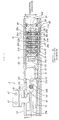
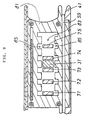
- Fig. 1 is a partial sectional view of a locking device of the present invention.
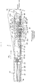
- Fig. 2 is a sectional view of Fig. 1 taken along the line A-A.
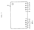
- Fig. 3 is a plan view of a card key of the first embodiment.
- Fig. 4 is a front view of the card key of Fig. 3.
- Fig. 5 is an external view of a suitcase incorporating the present invention.
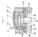
- Figs. 6, 7 and 8 are sectional views around a slider of the first embodiment.
- Fig. 9 is an explanatory view of a groove member of the present invention.
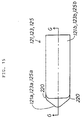
- Fig. 10 is a front view of a slider of the second embodiment.
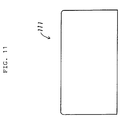
- Fig. 11 is a plan view of the slider of Fig. 10.
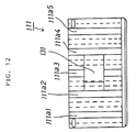
- Fig. 12 is a bottom view of the slider of Fig. 10.
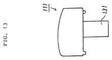
- Fig. 13 is a left side view of the slider of Fig. 10.
- Fig. 14 is a sectional view of the slider of Fig. 10 taken along F-F.
- Fig. 15 is a plan view of tumblers of the second embodiment.
- Fig. 16 is a sectional view of the tumblers of Fig. 15 taken along G-G.
- Fig. 17 is a bottom view of the tumblers of Fig. 15.
- Fig. 18 is a front view of the tumblers of Fig. 15.
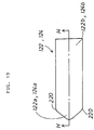
- Fig. 19 is a plan view of the tumblers of the second embodiment.
- Fig. 20 is a sectional view of the tumblers of Fig. 19 taken along the line H-H.
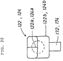
- Fig. 21 is a bottom view of the tumblers of Fig. 19.
- Fig. 22 is a front view of the tumblers of Fig. 19.
- Fig. 23 is a plan view of a card key of the second embodiment.
- a suitcase 1 comprises a grip 7 and a case member 9 as shown in Fig. 5.
- the case member 9 consists of a first case 9A and a second case 9B.
- the grip 7 is positioned on the suitcase 9 at the point the first case 9A and the second case 9B are combined.
- a locking device 3 is constructed between the first case 9A and the second case 9B adjacent to the grip 7.
- the locking device 3 comprises a slider 11, five tumblers 21 through 25, a first engaging projection 31, a first receiving portion 33, a second engaging projection 35, a second receiving portion 37, a first main body 41 and a second main body 43.
- the second main body 43 is fixed to the second case 9B by means of a plurality of fixing machine screws 45.
- An aperture 43a is formed on the second main body 43 in the direction where the first case 9A is moved to close the two cases 9A and 9B.
- the second main body 43 further comprises an aperture 43b in the first main body 41 side.
- the second receiving portion 37 is a cast made of light alloy, and has a pre-determined thickness of da as illustrated in Fig. 2.
- One end 37a of the second receiving portion 37 is T-shaped, while the other end 37b which projects out of the second main body 43 through the aperture 43b is U-shaped.
- This projecting portion of the end 37b is rotatably fixed to an axis member 46. Both ends of the axis member 46 are fixed to the first main body 41.
- a hook 37c is formed in the middle of the second receiving portion 37.
- the second receiving portion 37 is prevented from moving in the transverse and the height directions by the second main body 43.
- the second receiving portion 37 is
- the second engaging projection 35 is fixed to the first case 9A by means of two fixing machine screws 47.
- This second engaging projection 35 is constructed such that the hook 35a of the projection 35 is inserted into the second main body 43 through the aperture 43a of the second main body 43 when the first case 9A and the second case 9B are combined.
- the hook 35a of the second engaging projection 35 meshes with the hook 37c of the second receiving portion 37 as shown in Fig. 1 in order to keep the two cases 9A and 9B combined.
- An iron framework member 51 is fixed to the second main body 43 between the second receiving portion 37 and the second case 9B by means of a plurality of fixing machine screws 45.
- One end 51a of the framework member 51 is formed between the first main body 41 and the second case 9B, and stretches to the middle of the first main body 41. This end 51a thus supports a first axis member 53 such that the first axis member 53 is fixed to a pre-determined point of the second case 9B in the first main body 41.
- One end of a linking member 55 is rotatably fixed to the first axis member 53, and a second axis member 57 is supported on the other end of the linking member 55.
- the second axis member 57 rotates along a circumference EK shown with an alternate long and two short dashes line in Fig. 2 with the center being the first axis member 53.
- Both ends of the second axis member 57 are rotatably fixed to the first main body 41 as shown in Figs. 1 and 2.
- the components of the instant invention act in cooperation with each other as follows.
- the first main body 41 fluctuates along an alternate long and two short dashes line with the first and second axis members 53 and 57 being its axes.
- the first main body 41 then moves in the directions of the arrow YA and an arrow YB.
- the second receiving portion 37 linked to the first main body 41 slides in the direction of the arrow YB in accordance with the movement of the body 41. Consequently, as illustrated in Fig. 1, the hook 35a of the second engaging projection 35 engages with the hook 37c of the second receiving portion 37 until the second receiving portion 37 moves in the direction of the arrow YB such that the suitcase 1 is locked.
- the hooks 35a and 37c are disengaged. The suitcase 1 is thus unlocked, enabling the first case 9A and the second case 9B to be separated.
- the slider 11 is mounted inside the first main body 41, and can slide in the longitudinal direction of the first main body 41. The movement of the slider 11 in the transverse and the height directions is controlled.
- a slit 59 is formed in the first main body 41 along one side 11b of the slider 11 as illustrated in Fig. 1, Fig. 6 describing the details of the slider 11 and Fig. 7 showing a sectional view taken along B-B of Fig. 6.
- a concave member 60 is formed adjacent to the slit 59 in opposition to the side 11b of the slider 11. The slit 59 guides the card key 5 along the side 11b of the slider 11. The concave member 60 determines the maximum amount of projections of the tumblers 21 through 25.
- the first engaging projection 31 is connected with the slider 11a in the second case 9B side of the slider 11. As shown in Fig. 2 and Fig. 8 illustrating the details of Fig. 2, the first engaging projection 31 is L-shaped, and is inserted into the second case 9B through an opening 9Ba formed in the second case 9B. Adjacent to the opening 9Ba is the first receiving portion 33 which is a part of the second case 9B.
- the first engaging projection 31 is positioned such that a projecting portion 31a of the engaging projection 31 is opposite to the first receiving portion 33 when the slider 11 is located as illustrated in Fig. 2. Since the projecting portion 31a engages with the first receiving portion 33, the first main body 41 cannot be pulled up in the direction of the arrow YA.
- the tumblers 21 through 25 are provided on the slider 11 at the same intervals in the longitudinal direction of the slider 11.
- the tumblers 21 through 25 are slidingly inserted into the slider 11 in the transverse direction of the slider 11. Openings 11a1 through 11a5 are formed along the tumblers 21 through 25 in the side of case 9B as shown in Figs. 2, 7 and 8.
- the tumblers 21 through 25 are equipped with tapered tips 21a through 25a and body portions 21b through 25b as shown in Fig. 6.
- Coil springs 61 are provided inside the body portions 21b through 25b in the slider 11. The coil springs 61 actuate the tumblers 21 through 25 in the direction from the slider 11 to the slit 59.
- rectangular engaging projections 71 through 75 are located on pre-determined points of the tumblers 25 in the side of the second case 9B.
- the engaging projections 71 through 75 protrude outside the slider 11 in the side of the second case 9B via the openings 11al through 11a5 of the slider 11.
- a groove-forming member 81 is provided adjacent to the openings 11a1 through 11a5 of the slider 11 in the side of the second case 9B of the first main body 41.
- the groove-forming member 81 is equipped with a groove 83 and side slots 85 as shown in Fig. 9 which shows a sectional view of Fig. 2 taken on the line C-C.
- Fig. 9 illustrates, the slider 11 freely slides in the longitudinal direction when all of the engaging projections 71 through 75 are positioned inside the groove 83.
- the slider 11 cannot slide in the longitudinal direction.
- Relative positions of the engaging projections 71 through 75 and the groove 83 are determined in accordance with the projections of the tumblers 21 through 25 from the slider 11 into the slit 59.
- the projections into the slit 59 change according to the sliding of the card key 5 shown in Figs. 3 and 4.
- the card key has a plurality of holes 87 at the same intervals as the tumblers 21 through 25.
- the holes 87 receive the acuminate members 21a through 25a.
- the holes 87 are formed at the pre-determined points A through E.
- a pre-determined size e.g. full, large, medium, small or none, is selected for each of the points A through E.
- the holes 87 are formed at predetermined points of the card key 5.
- the points A, B, C, D and E are bilaterally symmetrical with their center being the center line in the longitudinal direction of the card key 5. The card key 5 is thus able to be inserted into the slit 59 from both directions.
- the diameters of the holes 87 of the card key 5 and the positions of the engaging projections 71 through 75 of the tumblers 21 through 25 are orderly determined. As shown in Fig. 6, all of the engaging projections 71 through 75 are located inside the groove 83 as illustrated in Fig. 9 only when the tumblers 21 through 25 engage with the card key 5, and thus the slider 11 can slide in the longitudinal direction.
- At least one of the points A through E of the holes 87 is a full hole.
- This hole indicates, for instance, a hole through which the tumbler 23 protrudes till the tapered tip 23a reaches the concave member 60 as shown in Fig. 6.
- the tumblers 21 through 25 are constructed, in the case of the tumbler 23, such that a boundary member 23c separating the tapered tip 23a and the body portion 23b abuts an inside edge 5E of the full hole at point C.
- the boundary member 23C is formed between the tapered tip 23a and the body portion 23b.
- the boundary member 23c abuts the card key 5 more vertically than the tapered tip 23a.
- the tumblers 21 through 25 engage with the smaller holes (large, medium and small), the inside edge 5E abuts the tapered tips 21a through 25a. In this case, the tumblers 21 through 25 do not receive great pushing force in the sliding direction of the card key 5 even when the card key 5 slides. The tumblers 21 through 25 receive great pushing force in the direction where the tumblers 21 through 25 are pushed.
- the card 5 key slides in the slit 59 till the key 5 engages with the tumblers 21 through 25 as shown in Fig. 6.
- the tumblers 21 through 25 are successively pushed into the slider 11 in accordance with the sliding of the card key 5 and the card key 5 slides in the slit 59.
- at least one of the engaging projections 71 through 75 is positioned inside the engaging concave member 85, and thus the slide 11 cannot slide.
- the first engaging projection 31 moves in the direction of the arrow YB when the card key slides in the direction of the arrow YB in Fig. 2. Accordingly, the first main body 41 can be pulled up in the direction of the arrow YA, so that the locking device 3 is unlocked without stopping of the card key 5 by steps or the like.
- the first engaging projection 31 moves in the reverse direction of the arrow YB when the card key 5 slides in the slit 59 in the reverse direction of the arrow YB. Therefore, the first main body 41 cannot be pulled up in the direction of the arrow YA, so that the locking device 3 is also locked without stopping of the card key 5 by steps or the like.
- the suitcase 1 in the aforementioned embodiment can be unlocked or locked by sliding the card key 5 in the slit 59 mounted adjacent to the grip 7 without stopping of the card key by steps or the like. Therefore, the card key 6 can effect unlocking or locking more smoothly than a conventional card key.
- a slider 111, tumblers 121 through 125, and a card key 105 are employed in this embodiment instead of the slider 11, the tumblers 21 through 25, and the card key 5 of the first embodiment, respectively.
- the slider 111 comprises a first engaging projection 131, openings 111a1 through 111a5 and receiving chambers 111b1 through 111b5.
- the first engaging projection 131 and the openings 111a1 through 111a5 have almost the same structures as the first engaging projection 31 and the openings 11a1 through 11a5 of the first embodiment.
- the receiving chambers 111b1 through 111b5 have quadrilateral sections.
- the tumblers 121 through 125 are slidingly inserted into the receiving chambers lllbl through 111b5.
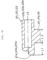
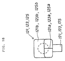
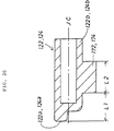
- the tumblers 121, 123 and 125 comprise tapered tips 121a, 123a and 125a, quadrilateral tube-like body portions 121b, 123b and 125b, and engaging projections 171, 173 and 175, respectively.
- the tapered tips 121a, 123a and 125a are formed below an axis JC of the quadrilateral body portions 121b, 123b and 125b as shown in Fig. 16.
- Dimensions L1 and L2 of the engaging projections 171, 173 and 175 in Fig. 16 are selected from Table 1, No. 1 through No. 3.
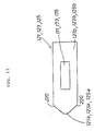
- the tumblers 122 and 124 comprise tapered tips 122a and 124a, quadrilateral tube-like body portions 122b and 124b, and engaging projections 172 and 174, respectively, as shown in Figs. 19 and 20.
- the tapered tips 122a and 124a are formed above the axis JC of thequadrilateral body portions 122b and 124b as illustrated in Fig. 20.
- Dimensions L1 and L2 of the engaging projections 172 and 174 in Fig 20 are selected from Table 1, No. 1 through No. 3 shown above.
- the card key 105 shown in Fig. 23 changes the projecting portions of the tumblers 121 through 125 inserted into the slider 111.
- the card key 105 is provided with a plurality of holes 187.
- the holes 187 are positioned at points AL, BL, CL, DL and EL in Fig. 23 in accordance with the positions of the tumblers 121 through 125.
- the points AL, CL and EL are provided along a line LL1, and the points BL and DL are along a line LL2.
- the centers of the tapered tips 121a, 123a and 125s are on the line LL1 during engagement with the holes 187.
- the centers of the tapered tips 122a and 124a are on the line LL2 during engagement with the holes 187.
- Dimensions D1 and D2 of the holes 187 are selected from Table 2, No. 1 through No. 3.
- Table 1 and Table 2 are selected for each tumbler, the predetermined portions of the tumblers project out and the slider 111 can slide in the longitudinal direction.
- At least one of the points AL through EL for the holes 187 is a full hole.
- the tapered tips 121a through 125a reach the concave member 60 through the full hole, wherein boundary members 220 of the tumblers 121 through 125 in Figs. 15 and 19 abut an inner edge 230 of the full hole in Fig. 23, as in the first embodiment.
- the boundary members 220 are formed between the tapered tips 121a through 125a and the quadrilateral body portions 121b and 125b. The boundary members 220 abut the card key 105 more vertically in the sliding direction than the tapered tips 121a through 125a.
- the tumblers 121 through 125 engage with the smaller hole (No. 2 in Table 2), the inner edge 230 of the smaller hole abuts the tapered tips 121a through 125a. If No.3 in Table 2 is selected for the holes which does not form a hole, the tapered tips 121a through 125a are not inserted into the card key 105. If No. 2 or No. 3 in Table 2 is selected, the tumblers 121 through 125 does not receive great pushing force in the sliding direction from the card key 105 during sliding of the card key. When No. 2 in Table 2 is selected, the tumblers 121 through 125 receive great pushing force in the direction where the tumblers are pushed into the slider 111.
- the locking device 3 can attain locking or unlocking operation by sliding the card key without stops by a step portion.
- the tapered tips 121a, 123a and 125a are formed in the upper position, and the tapered tips 122a and 124a are in the lower position.
- the tumblers 121 through 125 are placed in a line, but the holes 187 and the tapered tips 121a through 125a are positioned in two lines. Accordingly, a wider variety of alternatives for unlocking or locking operation can be made in this embodiment than simply selecting from three types of dimensions for five tumblers placed in a line. A locking device difficult to break with simple structure can be thus provided.
- This invention is not limited to the embodiment illustrated and described as above, but can be applied to a wide variety of locking devices.
- the configuration of the card key and the holes, the number of the holes and the tumblers and the like do not have to be the same as in this embodiment.
- pushing force can be adjusted by changing the quality or configuration of the tapered tips of the tumblers, though the pressure is controlled by changing the angle at which the tumblers abuts the edges of the holes of the card key in the instant invention.
- the tapered tips of the tumblers can be positioned in the left or right of the axis of the tumblers instead of the tapered tips the centers of which are positioned along the axis or above or below the axis as in the aforementioned embodiments.
- the tapered tips can be also located on pre-determined area of the front of the tumblers with the front being divided lengthwise and crosswise into a pre-determined number of the predetermined area.
Landscapes
- Lock And Its Accessories (AREA)
- Purses, Travelling Bags, Baskets, Or Suitcases (AREA)
- Bag Frames (AREA)
- Closures For Containers (AREA)
Claims (11)
- Schloß mit einem einen Kanal (83) aufweisenden Schließkörper (81), wobei dieser Kanal (83) eine Vielzahl von senkrecht dazu angeordneten Seitenschlitzen (85) besitzt, mit einem verbundenen Gleitstück (11; 111) zum Ein- und Ausrücken eines Schließvorsprunges (31; 131) bei der gleitenden Bewegung des Gleitstücks (11; 111) zwischen einer verriegelten und einer unverriegelten Position, mit einer Vielzahl von Zuhalteelementen (21 - 25; 121 - 125) am Gleitstück (11; 111), die zwischen einer vorgeschobenen und einer zurückgezogenen Position verschiebbar sind, wobei jedes der Vielzahl von Zuhalteelementen (21 - 25; 121 - 125) eine verjüngte Spitze (21a 25a; 121a - 125a) an einem äußeren Ende eines Hauptstücks (21b - 25b; 121b - 125b) und einen in den Kanal (83) eingreifenden Vorsprung (71 - 75; 171 - 175) an diesem Hauptstück aufweist, und mit Führungsmitteln zur Führung einer Verschlußkarte (5; 105) entlang einer und in eine Längsbahn neben dem Gleitstück (11; 111) und den verjüngten Spitzen (21a - 25a; 121a - 125a) der Vielzahl von Zuhalteelementen (21 - 25; 121 - 125), wobei die Verschlußkarte (5; 105) beabstandete Ausnehmungen (A - E; AL - EL) zur Aufnahme der verjüngten Spitzen (21a - 25a; 121a - 125a) der Zuhalteelemente (21 - 25; 121 - 125) aufweist, deren Größe so gewählt ist, daß die verjüngten Spitzen (21a - 25a; 121a - 125a) jeweils eines der Vielzahl von Zuhalteelementen bis zu einer Tiefe aufgenommen werden, die jedes Zuhalteelement (21 - 25; 121 - 125) an einer Stelle plaziert, an der ihr Vorsprung (71 - 75; 171 - 175) zum Gleiten in den Kanal (83) positioniert wird, dadurch gekennzeichnet, daß wenigstens eine der Ausnehmungen (C; AL - EL) so dimensioniert ist, daß die verjüngte Spitze (23a; 121a - 125a) eines entsprechenden der Vielzahl von Zuhalteelementen (21 - 25; 121 - 125) bis zu einer Tiefe aufgenommen wird, bei der eine Seite der Ausnehmung (C; AL - EL) in Kontakt mit diesem darin angeordneten Zuhalteelement an einer Stelle eines Grenzelementes (23c; 220) steht, das zwischen der verjüngten Spitze (23; 121a - 125a) und dem Hauptstück (23b; 121b - 125b) angrenzend an dieses Hauptstück (23b; 121b - 125b) ausgebildet ist, wobei beim Einschieben der Verschlußkarte (5; 105) entlang der Bahn in eine vorgegebene Richtung diejenigen Zuhalteelemente, deren verjüngte Spitzen Aufnahme in den Ausnehmungen gefunden haben, und in Kombination damit das Gleitstück (11; 111) entlang der Bahn zwischen der verriegelten und der entriegelten Position verschoben werden, und wobei - nachdem das Gleitstück seine äußerste Position erreicht hat - das weitere Verschieben der Verschlußkarte in die selbe Richtung und aus der Bahn heraus durch Lösen der Zuhalteelemente (21 - 25; 121 - 125) aus den Ausnehmungen (A - E; AL - EL) ermöglicht wird.
- Schloß nach Anspruch 1, bei dem die Zuhalteelemente (21 - 25; 121 - 125) senkrecht zum Kanal (83) und parallel zu den Seitenschlitzen (85) verschiebbar sind zur gleitenden Bewegung darin zwischen der vorgeschobenen und der zurückgezogenen Position.
- Schloß nach Anspruch 1 oder 2, bei dem die Zuhalteelemente (21 - 25; 121 - 125) Vorspannmittel (61) an einem inneren Endbereich des Hauptstücks (21b - 25b) zum Vorspannen der verjüngten Spitze (21a - 25a; 121a - 125a) zur vorgeschobenen Position hin aufweisen, wobei der Vorsprung (71 - 75; 171 - 175) jedes der Zuhalteelemente (21 - 25; 121 - 125) entlang deren Länge so positioniert ist, daß das Gleitstück (11; 111) zwischen der verriegelten und der unverriegelten Position nur dann gleiten kann, wenn jedes der Zuhalteelemente (21 - 25; 121 - 125) zwischen der vorgeschobenen und der zurückgezogenen Position an einer Stelle angeordnet ist, an der der Vorsprung (71 - 75; 171 - 175) so positioniert ist, daß er im Kanal (83) gleiten kann.
- Schloß nach einem der vorhergehenden Ansprüche, bei dem die Führungsmittel ein Führungsglied aufweisen, das parallel und beabstandet von der Bahn neben dem Gleitstück (11; 111) und den verjüngten Spitzen (21a - 25a; 121a - 125a) der Zuhalteelemente (21 - 25; 121 - 125) angeordnet ist.
- Schloß nach Anspruch 4, bei dem das Führungsglied ein konkaves Glied (60) ist.
- Schloß nach Anspruch 5, bei dem das konkave Glied (60) die Ausbildung eines Schlitzes aufweist, der parallel und beabstandet zu der Bahn neben dem Gleitstück (11; 111) und den verjüngten Spitzen (21a - 25a; 121a - 125a) der Zuhalteelemente (21 - 25; 121 - 125) angeordnet ist, zur Aufnahme von deren verjüngten Spitzen, wobei die Verschlußkarte (5; 105) neben dem Gleitstück (11; 111) gehalten wird.
- Schloß nach einem der vorhergehenden Ansprüche, bei dem die Ausnehmungen (A - E; AL - EL) in der Verschlußkarte Löcher durch die Verschlußkarte (5; 105) aufweisen.
- Schloß nach Anspruch 7, bei dema. die verjüngten Spitzen (21a - 25a) eine im wesentlichen kegelstumpfförmige Gestalt aufweisen, undb. die Ausnehmungen (A - E) in der Verschlußkarte (5) kreisförmige Löcher aufweisen.
- Schloß nach Anspruch 7, bei dema. die verjüngten Spitzen (121a - 125a) einen im wesentlichen rechteckigen Querschnitt aufweisen, undb. die Ausnehmungen (AL - EL) in der Verschlußkarte (105) rechteckige Löcher aufweisen.
- Schloß nach Anspruch 8 oder 9, bei dema. die verjüngten Spitzen (21a - 25a; 121a - 125a) im wesentlichen die selbe Gestalt aufweisen, undb. die Ausnehmungen (A - E; AL - EL) in der Verschlußkarte (5; 105) Löcher in unterschiedlicher Gestalt enthalten.
- Schloß nach einem der Ansprüche 8 bis 10, bei dema) einige der verjüngten Spitzen (121a, 123a, 125a) entlang einer Linie angeordnet sind, die von anderen der verjüngten Spitzen (122a, 124a) versetzt sind, undb) die Ausnehmungen (AL - EL) durch die Verschlußkarte (105) in einem Muster versetzt angeordnet sind zur Anpassung an die verjüngten Spitzen (121a - 125a).
Applications Claiming Priority (4)
| Application Number | Priority Date | Filing Date | Title |
|---|---|---|---|
| JP67597/90 | 1990-03-16 | ||
| JP6759790 | 1990-03-16 | ||
| JP30991/91 | 1991-02-26 | ||
| JP3030991A JPH04213674A (ja) | 1990-03-16 | 1991-02-26 | 施錠装置 |
Publications (3)
| Publication Number | Publication Date |
|---|---|
| EP0447906A2 EP0447906A2 (de) | 1991-09-25 |
| EP0447906A3 EP0447906A3 (de) | 1991-10-16 |
| EP0447906B1 true EP0447906B1 (de) | 1994-08-03 |
Family
ID=26369451
Family Applications (1)
| Application Number | Title | Priority Date | Filing Date |
|---|---|---|---|
| EP91103649A Expired - Lifetime EP0447906B1 (de) | 1990-03-16 | 1991-03-09 | Schloss, welches mittels einer Karte mit verschiedenen Löchern betätigbar ist |
Country Status (5)
| Country | Link |
|---|---|
| EP (1) | EP0447906B1 (de) |
| AT (1) | ATE109540T1 (de) |
| CA (1) | CA2037759A1 (de) |
| DE (1) | DE69103182T2 (de) |
| MX (1) | MX173355B (de) |
Families Citing this family (5)
| Publication number | Priority date | Publication date | Assignee | Title |
|---|---|---|---|---|
| TW205081B (de) * | 1991-10-24 | 1993-05-01 | Cardlock Pty Ltd | |
| JPH0711208B2 (ja) * | 1991-11-29 | 1995-02-08 | 田村プラスチック製品株式会社 | 施錠装置 |
| SE508334C2 (sv) | 1996-09-16 | 1998-09-28 | Assa Ab | Låsanordning |
| FR2779561B1 (fr) * | 1998-06-09 | 2001-01-19 | Valeo Securite Habitacle | Agencement pour le blocage longitudinal d'un support de donnees rigide dans un dispositif d'echange de donnees |
| CN112012587B (zh) * | 2020-09-15 | 2024-07-12 | 杭州小安物联科技有限公司 | 机柜双控锁 |
Family Cites Families (2)
| Publication number | Priority date | Publication date | Assignee | Title |
|---|---|---|---|---|
| FR1010520A (fr) * | 1948-09-04 | 1952-06-12 | Serrure de sûreté | |
| US4754630A (en) * | 1985-12-18 | 1988-07-05 | Kabushiki Kaisha Saikousha | Locking device |
-
1991
- 1991-03-07 CA CA002037759A patent/CA2037759A1/en not_active Abandoned
- 1991-03-09 AT AT91103649T patent/ATE109540T1/de not_active IP Right Cessation
- 1991-03-09 DE DE69103182T patent/DE69103182T2/de not_active Expired - Fee Related
- 1991-03-09 EP EP91103649A patent/EP0447906B1/de not_active Expired - Lifetime
- 1991-03-11 MX MX024850A patent/MX173355B/es unknown
Also Published As
| Publication number | Publication date |
|---|---|
| EP0447906A3 (de) | 1991-10-16 |
| DE69103182T2 (de) | 1995-03-23 |
| CA2037759A1 (en) | 1991-09-17 |
| ATE109540T1 (de) | 1994-08-15 |
| DE69103182D1 (de) | 1994-09-08 |
| MX173355B (es) | 1994-02-22 |
| EP0447906A2 (de) | 1991-09-25 |
Similar Documents
| Publication | Publication Date | Title |
|---|---|---|
| US4518212A (en) | Multiple pin electrical plug | |
| US5375444A (en) | Multi-key core lock assembly | |
| US5020342A (en) | Safety lock | |
| DE4201936C2 (de) | Magnetkartenschloß | |
| EP1942243B1 (de) | Mehrfunktionsschloss | |
| EP0447906B1 (de) | Schloss, welches mittels einer Karte mit verschiedenen Löchern betätigbar ist | |
| US3910083A (en) | Combination changing cylinder lock | |
| EP2406444A1 (de) | Zylinderschloss- und schlüsselkombination | |
| GB2082667A (en) | Fastening device for apertured members | |
| EP0903455A2 (de) | Einbruchsicherung für ein Schloss mit plattenförmigen Zuhaltungen | |
| US3230749A (en) | Key-operated lock | |
| SI9200156A (en) | Locking system consisting of a key and its associated locking cylinder | |
| US6186606B1 (en) | Lateral File Locking System | |
| US3937046A (en) | Multi-combination push button lock | |
| US3068682A (en) | Padlock with dual blockers | |
| US3978700A (en) | Safe deposit lock construction with changeable tumbler mechanism | |
| JPH01158185A (ja) | 可動押し出し部材付き鍵,安全ロックシリンダ,及び錠 | |
| US4756173A (en) | Zipper lock | |
| JP2022529143A (ja) | スーツケース用ジッパー錠及びスーツケース | |
| US3514981A (en) | Lock box | |
| US3793857A (en) | Removable cylinder for a lock | |
| US3654783A (en) | Lock with readily interchangeable key | |
| US4682484A (en) | Tumbler plate cylinder lock | |
| EP0744517B1 (de) | Schloss mit flachen Zuhaltungen und Wechselkombination | |
| US4069693A (en) | Cylinder lock assembly |
Legal Events
| Date | Code | Title | Description |
|---|---|---|---|
| PUAI | Public reference made under article 153(3) epc to a published international application that has entered the european phase |
Free format text: ORIGINAL CODE: 0009012 |
|
| PUAL | Search report despatched |
Free format text: ORIGINAL CODE: 0009013 |
|
| AK | Designated contracting states |
Kind code of ref document: A2 Designated state(s): AT BE CH DE DK ES FR GB GR IT LI LU NL SE |
|
| AK | Designated contracting states |
Kind code of ref document: A3 Designated state(s): AT BE CH DE DK ES FR GB GR IT LI LU NL SE |
|
| 17P | Request for examination filed |
Effective date: 19920302 |
|
| 17Q | First examination report despatched |
Effective date: 19920717 |
|
| GRAA | (expected) grant |
Free format text: ORIGINAL CODE: 0009210 |
|
| AK | Designated contracting states |
Kind code of ref document: B1 Designated state(s): AT BE CH DE DK ES FR GB GR IT LI LU NL SE |
|
| PG25 | Lapsed in a contracting state [announced via postgrant information from national office to epo] |
Ref country code: NL Effective date: 19940803 Ref country code: LI Effective date: 19940803 Ref country code: GR Free format text: LAPSE BECAUSE OF FAILURE TO SUBMIT A TRANSLATION OF THE DESCRIPTION OR TO PAY THE FEE WITHIN THE PRESCRIBED TIME-LIMIT Effective date: 19940803 Ref country code: ES Free format text: THE PATENT HAS BEEN ANNULLED BY A DECISION OF A NATIONAL AUTHORITY Effective date: 19940803 Ref country code: DK Effective date: 19940803 Ref country code: CH Effective date: 19940803 Ref country code: BE Effective date: 19940803 Ref country code: AT Effective date: 19940803 |
|
| REF | Corresponds to: |
Ref document number: 109540 Country of ref document: AT Date of ref document: 19940815 Kind code of ref document: T |
|
| REF | Corresponds to: |
Ref document number: 69103182 Country of ref document: DE Date of ref document: 19940908 |
|
| ITF | It: translation for a ep patent filed | ||
| PG25 | Lapsed in a contracting state [announced via postgrant information from national office to epo] |
Ref country code: SE Effective date: 19941103 |
|
| REG | Reference to a national code |
Ref country code: CH Ref legal event code: PL |
|
| ET | Fr: translation filed | ||
| NLV1 | Nl: lapsed or annulled due to failure to fulfill the requirements of art. 29p and 29m of the patents act | ||
| PG25 | Lapsed in a contracting state [announced via postgrant information from national office to epo] |
Ref country code: LU Free format text: LAPSE BECAUSE OF NON-PAYMENT OF DUE FEES Effective date: 19950331 |
|
| PLBE | No opposition filed within time limit |
Free format text: ORIGINAL CODE: 0009261 |
|
| STAA | Information on the status of an ep patent application or granted ep patent |
Free format text: STATUS: NO OPPOSITION FILED WITHIN TIME LIMIT |
|
| 26N | No opposition filed | ||
| PGFP | Annual fee paid to national office [announced via postgrant information from national office to epo] |
Ref country code: DE Payment date: 19970122 Year of fee payment: 7 |
|
| PGFP | Annual fee paid to national office [announced via postgrant information from national office to epo] |
Ref country code: GB Payment date: 19970226 Year of fee payment: 7 |
|
| PGFP | Annual fee paid to national office [announced via postgrant information from national office to epo] |
Ref country code: FR Payment date: 19970228 Year of fee payment: 7 |
|
| PG25 | Lapsed in a contracting state [announced via postgrant information from national office to epo] |
Ref country code: GB Free format text: LAPSE BECAUSE OF NON-PAYMENT OF DUE FEES Effective date: 19980309 |
|
| PG25 | Lapsed in a contracting state [announced via postgrant information from national office to epo] |
Ref country code: FR Free format text: THE PATENT HAS BEEN ANNULLED BY A DECISION OF A NATIONAL AUTHORITY Effective date: 19980331 |
|
| GBPC | Gb: european patent ceased through non-payment of renewal fee |
Effective date: 19980309 |
|
| PG25 | Lapsed in a contracting state [announced via postgrant information from national office to epo] |
Ref country code: DE Free format text: LAPSE BECAUSE OF NON-PAYMENT OF DUE FEES Effective date: 19981201 |
|
| REG | Reference to a national code |
Ref country code: FR Ref legal event code: ST |
|
| PG25 | Lapsed in a contracting state [announced via postgrant information from national office to epo] |
Ref country code: IT Free format text: LAPSE BECAUSE OF NON-PAYMENT OF DUE FEES;WARNING: LAPSES OF ITALIAN PATENTS WITH EFFECTIVE DATE BEFORE 2007 MAY HAVE OCCURRED AT ANY TIME BEFORE 2007. THE CORRECT EFFECTIVE DATE MAY BE DIFFERENT FROM THE ONE RECORDED. Effective date: 20050309 |