EP0447675A1 - Ressort à gaz à longueur réglable - Google Patents
Ressort à gaz à longueur réglable Download PDFInfo
- Publication number
- EP0447675A1 EP0447675A1 EP90125386A EP90125386A EP0447675A1 EP 0447675 A1 EP0447675 A1 EP 0447675A1 EP 90125386 A EP90125386 A EP 90125386A EP 90125386 A EP90125386 A EP 90125386A EP 0447675 A1 EP0447675 A1 EP 0447675A1
- Authority
- EP
- European Patent Office
- Prior art keywords
- valve
- gas spring
- valve pin
- cylindrical section
- housing space
- Prior art date
- Legal status (The legal status is an assumption and is not a legal conclusion. Google has not performed a legal analysis and makes no representation as to the accuracy of the status listed.)
- Granted
Links
Images
Classifications
-
- F—MECHANICAL ENGINEERING; LIGHTING; HEATING; WEAPONS; BLASTING
- F16—ENGINEERING ELEMENTS AND UNITS; GENERAL MEASURES FOR PRODUCING AND MAINTAINING EFFECTIVE FUNCTIONING OF MACHINES OR INSTALLATIONS; THERMAL INSULATION IN GENERAL
- F16F—SPRINGS; SHOCK-ABSORBERS; MEANS FOR DAMPING VIBRATION
- F16F9/00—Springs, vibration-dampers, shock-absorbers, or similarly-constructed movement-dampers using a fluid or the equivalent as damping medium
- F16F9/02—Springs, vibration-dampers, shock-absorbers, or similarly-constructed movement-dampers using a fluid or the equivalent as damping medium using gas only or vacuum
- F16F9/0209—Telescopic
- F16F9/0245—Means for adjusting the length of, or for locking, the spring or dampers
-
- Y—GENERAL TAGGING OF NEW TECHNOLOGICAL DEVELOPMENTS; GENERAL TAGGING OF CROSS-SECTIONAL TECHNOLOGIES SPANNING OVER SEVERAL SECTIONS OF THE IPC; TECHNICAL SUBJECTS COVERED BY FORMER USPC CROSS-REFERENCE ART COLLECTIONS [XRACs] AND DIGESTS
- Y10—TECHNICAL SUBJECTS COVERED BY FORMER USPC
- Y10T—TECHNICAL SUBJECTS COVERED BY FORMER US CLASSIFICATION
- Y10T137/00—Fluid handling
- Y10T137/8593—Systems
- Y10T137/86493—Multi-way valve unit
- Y10T137/86509—Sequentially progressive opening or closing of plural ports
-
- Y—GENERAL TAGGING OF NEW TECHNOLOGICAL DEVELOPMENTS; GENERAL TAGGING OF CROSS-SECTIONAL TECHNOLOGIES SPANNING OVER SEVERAL SECTIONS OF THE IPC; TECHNICAL SUBJECTS COVERED BY FORMER USPC CROSS-REFERENCE ART COLLECTIONS [XRACs] AND DIGESTS
- Y10—TECHNICAL SUBJECTS COVERED BY FORMER USPC
- Y10T—TECHNICAL SUBJECTS COVERED BY FORMER US CLASSIFICATION
- Y10T137/00—Fluid handling
- Y10T137/8593—Systems
- Y10T137/86493—Multi-way valve unit
- Y10T137/86815—Multiple inlet with single outlet
Definitions
- the invention relates to a length-adjustable gas spring according to the preamble of claim 1.
- Such length-adjustable gas springs are known for example from JP-U-51-153 392 and EP-B1-0 219 362.
- a conical or frustoconical transition section is formed between the two cylindrical sections of the valve pin.
- the invention is therefore based on the object of designing a gas spring of the generic type in such a way that damage to the ring seal serving to seal between the valve body interior and the adjacent housing space is avoided.
- the measures according to the invention ensure that even when the valve pin is moved to actuate or adjust the length of the gas spring, the ring seal always rests on the cylindrical portion of the larger diameter of the valve pin, so that when the valve is closed, the ring seal does not flex or shear.
- the measures according to the invention enable the further development according to claim 3.
- the further embodiment according to claim 4 ensures that no significant mechanical stresses of the ring seal occur at the transition between the groove and the ring seal, which are in any case lower because the essential areas the edges of the groove extend approximately in the direction of displacement.
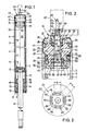
- the length-adjustable gas spring shown in Fig. 1 has a housing 1, which consists essentially of two concentrically nested pipes with different diameters, namely an inner cylinder 2 and an outer cylinder 3.
- An annular space 4 is formed between the outer cylinder 3 and the inner cylinder 2 due to the different diameter of the inner cylinder 2 and the outer cylinder 3.
- an approximately annular piston 5 is arranged axially displaceably, which is sealed gas-tight with its outer circumference against the inner wall 7 of the inner cylinder 2 via a sealing ring 6.
- the piston 5 is attached to one end of a piston rod 8 guided coaxially to the housing 1.
- This piston rod 8 is led out of one end of the housing 1.
- the housing 1 is closed by a cover plate 9, which is sealed gas-tight on its outer circumference by means of an annular seal 10 with respect to the inner wall 11 of the outer cylinder 3.
- the cover plate 9 is held axially outwards by a flange 12 of the outer cylinder 3.
- a centering piece 15, which bears against the inner wall 11 of the outer cylinder 3, is supported from the interior of the housing 1 and is provided with ribs 16 on which the inner cylinder 2 is radially supported, that is to say centered, with its inner wall 7.
- the inner cylinder 2 is also axially firmly supported on these ribs 16, that is to say axially fixed on one side.
- a valve 19 is arranged, by means of which the housing space 20 located in the inner cylinder 2 between the piston 5 and the valve 19 can be connected to or separated from the annular space 4 and thus the other housing space 17 .
- the valve 19 has a valve body 21, which in its axially central region is provided with an annular collar 22 which bears against the inner wall 11 of the outer cylinder 3, as a result of which the valve body 21 is centered in the outer cylinder 3.
- This annular collar 22 is the section of greatest diameter on the entire valve body 21. If one speaks in the description of "axial”, then this always refers to the central longitudinal axis 23 of the gas spring, which is also the axis of symmetry of all individual parts and assemblies.
- the collar 22 is followed by a centering collar 24 of smaller diameter, which lies against the inner wall 7 of the inner cylinder 2, whereby the latter is centered relative to the outer cylinder 3.
- the inner cylinder 2 lies with its associated edge against the facing side surface of the collar 22, as a result of which it is held axially.
- the centering collar 24 is again adjoined in the direction of the housing space 20 by an outer groove 25, the bottom 26 of which is formed by a sleeve-shaped section 27 of the valve body 21, the outer diameter of which is in turn smaller than the outer diameter of the centering collar 24.
- a side wall facing the collar 22 28 of the outer groove 25 is formed by the corresponding side surface of the centering collar 24 at the transition from this to the section 27.
- the other side wall 29 of the outer groove 25 facing the housing space 20 is formed by a cover 30.
- the annular collar 22 Seen axially towards the outside of the housing 1, the annular collar 22 is adjoined by an external groove 32, one side wall 33 of which, facing the other external groove 25, is formed by the corresponding side surface of the annular collar 22. Its bottom 34 is formed by an annular section 35 which adjoins the annular collar 22 and whose outer diameter is smaller than that of the annular collar 22.
- the side wall 36 of the outer groove 32 which is located on the outside of the housing 1, is formed by an annular disk 37.
- This ring disk 37 is arranged on an annular cylindrical guide section 38 of the valve body 21, the outside diameter of which is in turn smaller than that of the ring section 35.
- the ring disk 37 is press-fitted onto the cylindrical outer surface 39 of the guide section 38.
- the outer edge of the outer cylinder 3 is pressed around the outside of the annular disc 37 with a flange 40, whereby the entire valve 19 is held outwards and at the same time is pressed axially inwards against the inner cylinder 2.
- the valve body 21 consisting of the guide section 38, the ring section 35, the ring collar 22, the centering collar 24 and the sleeve-shaped section 27 is formed in one piece from plastic and - as is from the preceding description results - constructed symmetrically to the central longitudinal axis 23, so that it can be injection molded with a shape which is only separated in a plane transverse to the axis 23, which in turn is arranged in the region of the annular collar 22. From here, the valve body 21 tapers axially towards its ends, in stages.
- the annular disc 37 is made of metal.
- an outer ring seal 41 is arranged, which bears against the inner wall 11 of the outer cylinder 3 and thus prevents gas leakage in this area to the outside.
- the annular disk 37 and the adjacent region of the valve body 21 are provided with a cylindrical coaxial guide bore 42, to which a likewise cylindrical valve body interior 43 is connected.
- This inner space 43 has a larger diameter than the guide bore 42.
- An overflow channel 44 which penetrates the annular collar 22 radially and opens into the annular space 4 on its outside, opens into this interior space 43. At the outlet into the interior 43, the overflow channel 44 is provided with a throttle opening 45.
- a valve pin 46 is arranged in the valve body 21 and protrudes outward from the annular disc 37 and thus from the gas spring.
- This essentially stepped-cylindrical valve pin 46 is guided in the guide bore 42.
- an inner ring seal 47 is arranged, which is fixed axially outwards by the annular disk 37 and which bears radially on the one hand on a cylindrical section 48 of the valve pin 46 and on the other hand on the inner wall of the guide section 38, so that a gas leak through the guide bore 42 is excluded.
- the inner ring seal 47 is fixed axially in the direction of the housing space 20 by the transition on the valve body 21 to the guide bore 42.
- the cover 30 is pot-shaped, ie it has an outer annular web 52 which extends axially towards the outside of the gas spring and on which the side wall 29 of the outer groove 25 is formed. It also has an annular disk-shaped section 53.
- the ring web 52 is through a in a groove 54th bead 55 pressed in the sleeve-shaped section 27 is fastened to the section 27, as a result of which the cover 30 is fixed to the valve body 21. Since the cover 30 is also made of plastic, this is easy to implement.
- a ring cylinder web 56 extends axially outward from the annular disk-shaped section 53, against which the inner ring seal 50 bears.
- the cover 30 has a coaxial bore 57, the diameter of which is slightly larger than the diameter of the section 49 of the valve pin 46 in this area, so that an annular passage 58 is formed here.
- the cylindrical section 49 of the valve pin 46 has a slightly larger diameter d2 than the cylindrical section 48 of the valve pin 46, so that the transition from section 48 to section 49 is formed by an annular collar 59.
- shallow grooves 60 are formed in the cylindrical section 49, the edges 61 of which are rounded at the transition to the cylindrical outer surface 62 of the section 49, that is to say they are formed without edges, as can be seen in FIG. 3.
- the grooves 60 extend only so far from the collar 59 in the direction of the housing space 20, ie their length b is such that they do not match the inner ring seal 50 in the illustrated rest position of the valve pin 46, which corresponds to the closed position of the valve 19 overlap, so do not bridge them.
- the spacings of the ring seal 50 of the annular collar in the rest position of the valve pin 46 shown in FIG. 2 is therefore at least somewhat larger than the position b of the grooves 60.
- the inner ring seal 50 is therefore in continuous contact only with the cylindrical outer surface 62 of section 49, thus closes the valve body interior 43 gas-tight from the housing space 20.
- the valve pin 46 has a stop plate 63 at its end located in the housing space 20, so that it cannot be pushed out of the housing 1 by the gas pressure.
- the piston rod 8 If the piston rod 8 is pushed into the housing 1 with the valve 19 open, then the compressed gas in the housing flows in the manner described; if none or only one on the piston rod when the valve 19 is open little force is exerted, then the compressed gas flows in the opposite direction and pushes the piston 5 with the piston rod 8 in the opposite direction, ie out of the housing 1.
- the valve pin 46 When the valve pin 46 is released, the bridging of the inner ring seal 50 by the grooves 60 is released and the gas flow is thus interrupted.
- the piston 5 with the piston rod 8 then remains in a corresponding position relative to the housing and can spring against the forces exerted by the compressed gas on both sides.
- the valve pin 46 On its side lying outside the annular disk 37, that is to say outside the housing 1, the valve pin 46 is formed in one piece with a thin pin-like attachment, the diameter of which is significantly smaller than the diameter d1 of the adjacent cylindrical section 48.
- the transition from the Approach 64 to the cylindrical portion 48 formed by an annular collar 65 Proceeding from this ring collar 65, grooves 60 'are formed in the cylindrical outer surface 66 of the section 48 and are formed in the same way as the grooves 60. They therefore have well rounded edges 61' in the same way and a length b 'that is significantly smaller than the distance c of the inner ring seal 47 from the inner ring seal 47 in the rest position of the valve pin 46. These grooves 60 'serve to fill the gas spring with compressed gas.
- valve pin 46 is pushed into the valve body 21 by a corresponding attack on the pin-like extension 64 until the grooves 60 'the axially outer inner ring seal 47 bridged so that compressed gas can be pressed into the valve body interior 43 through the guide bore 42 and the grooves 60 ', from where it flows through the overflow channel 44 and the annular space 4 into the housing space 17 and through the passage duct 58 into the housing space 20.
- the cylindrical section 49 is completely lifted off the inner ring seal 50.
- a trigger cap 67 is fastened on the pin-like extension 64 and a corresponding opening force is exerted on it to open the valve.
- valve pin 46 is - as can be seen from the above description and the drawings - from the extension 64 to the stop plate 63 without constriction; it is gradually expanding in this direction. It can therefore be produced in a very simple manner by injection molding in a mold, the separating surface of which lies in the outer surface of the stop plate 63.
- the section of the cylindrical outer surface 62 between two adjacent grooves 60 has a width f which is at least equal to the width g of a groove 60.
- the width g of a groove 60 thus extends approximately over one eighth of the circumference of the cylindrical section 49, while the section between two adjacent grooves 60 extends over a width g which is at least approximately one eighth of this circumference. The same applies approximately to the grooves 60 'in the cylindrical section 48.
- the annular space 4 is a free space, i. H. on the one hand, it can only be a pure overflow space, which serves to connect the two housing spaces 17 and 20. On the other hand, it can also have the function of a compensation room if it is not connected to the housing room 17.
- the valve pin 46 can be made of a polyamide or an acetal resin.
Landscapes
- Engineering & Computer Science (AREA)
- General Engineering & Computer Science (AREA)
- Mechanical Engineering (AREA)
- Fluid-Damping Devices (AREA)
- Sliding Valves (AREA)
- Lift Valve (AREA)
- Check Valves (AREA)
- Safety Valves (AREA)
- Valve-Gear Or Valve Arrangements (AREA)
Priority Applications (1)
| Application Number | Priority Date | Filing Date | Title |
|---|---|---|---|
| AT90125386T ATE95592T1 (de) | 1990-03-21 | 1990-12-22 | Laengenverstellbare gasfeder. |
Applications Claiming Priority (2)
| Application Number | Priority Date | Filing Date | Title |
|---|---|---|---|
| DE4009035A DE4009035A1 (de) | 1990-03-21 | 1990-03-21 | Laengenverstellbare gasfeder |
| DE4009035 | 1990-03-21 |
Publications (2)
| Publication Number | Publication Date |
|---|---|
| EP0447675A1 true EP0447675A1 (fr) | 1991-09-25 |
| EP0447675B1 EP0447675B1 (fr) | 1993-10-06 |
Family
ID=6402707
Family Applications (1)
| Application Number | Title | Priority Date | Filing Date |
|---|---|---|---|
| EP90125386A Expired - Lifetime EP0447675B1 (fr) | 1990-03-21 | 1990-12-22 | Ressort à gaz à longueur réglable |
Country Status (6)
| Country | Link |
|---|---|
| US (1) | US5141210A (fr) |
| EP (1) | EP0447675B1 (fr) |
| JP (1) | JPH0514687U (fr) |
| AT (1) | ATE95592T1 (fr) |
| DE (2) | DE4009035A1 (fr) |
| ES (1) | ES2045740T3 (fr) |
Cited By (2)
| Publication number | Priority date | Publication date | Assignee | Title |
|---|---|---|---|---|
| DE4226180A1 (de) * | 1992-08-07 | 1994-02-10 | Suspa Compart Ag | Kolben-Kolbenstangen-Einheit und Verfahren zu deren Herstellung |
| NL9402181A (nl) * | 1994-12-21 | 1996-08-01 | Technics B V T | Gasveer en werkwijze voor het met gas onder druk vullen daarvan. |
Families Citing this family (12)
| Publication number | Priority date | Publication date | Assignee | Title |
|---|---|---|---|---|
| US5400995A (en) * | 1992-04-15 | 1995-03-28 | Hill-Rom Company, Inc. | IV pole with interior drag brake |
| DE4420914A1 (de) * | 1994-06-16 | 1995-12-21 | Suspa Compart Ag | Längenverstellbare Gasfeder und längenverstellbare Säule für Stühle, Tische mit einer längenverstellbaren Gasfeder |
| DE19506479A1 (de) * | 1995-02-24 | 1996-08-29 | Suspa Compart Ag | Mit Fluid gefüllte Zylinder-Kolbenstangen-Einheit, insbesondere Gasfeder |
| US5898961A (en) * | 1995-06-07 | 1999-05-04 | Hill-Rom, Inc. | Mobile support unit and attachment mechanism for patient transport device |
| DE19604962A1 (de) * | 1996-02-10 | 1997-08-14 | Suspa Compart Ag | Längenverstellbare Gasfeder |
| DE19714646A1 (de) * | 1997-04-09 | 1998-10-15 | Suspa Compart Ag | Längenverstellbare Gasfeder |
| US6336624B1 (en) * | 1997-11-24 | 2002-01-08 | Cabex Ag | Adjustable length column/support |
| WO1999053216A1 (fr) * | 1998-04-14 | 1999-10-21 | Cabex Ag | Amortisseur utilisant un fluide comme agent d'amortissement et reglable en longueur |
| US7007587B2 (en) * | 2003-07-23 | 2006-03-07 | Suspa Incorporated | Snap-in rotatable cylinder control |
| KR200348804Y1 (ko) * | 2004-02-05 | 2004-04-29 | 주식회사 한국가스스프링 | 가스 실린더용 밸브의 조립 구조물 |
| US20130248011A1 (en) * | 2012-03-21 | 2013-09-26 | Guo Yuan Hardware Co., Ltd. | Faucet control valve |
| DE102014100166A1 (de) * | 2014-01-09 | 2015-07-09 | Thyssenkrupp Bilstein Gmbh | Ventileinrichtung für ein Luftfederbein |
Citations (6)
| Publication number | Priority date | Publication date | Assignee | Title |
|---|---|---|---|---|
| US2485504A (en) * | 1945-11-28 | 1949-10-18 | Morgan Construction Co | Reciprocable valve |
| FR1334374A (fr) * | 1962-06-07 | 1963-08-09 | P Berthoud Ets | Perfectionnements aux distributeurs pour pulvérisateurs agricoles et autres |
| FR1344990A (fr) * | 1961-10-07 | 1963-12-06 | Grohe Armaturen Friedrich | Joint de soupape pour robinets, batteries mélangeuses et autres |
| GB1217263A (en) * | 1967-11-30 | 1970-12-31 | Stabilus Ind Handels Gmbh | Improvements in or relating to columns of adjustable length |
| EP0217013A1 (fr) * | 1985-08-31 | 1987-04-08 | Fritz Bauer + Söhne oHG | Ressort à gaz réglable en longueur |
| EP0219362A1 (fr) * | 1985-08-28 | 1987-04-22 | Airaxs.A. | Ressort pneumatique blocable |
Family Cites Families (8)
| Publication number | Priority date | Publication date | Assignee | Title |
|---|---|---|---|---|
| US2764181A (en) * | 1952-11-15 | 1956-09-25 | Lockheed Aircraft Corp | Valve packing installation |
| US2922497A (en) * | 1956-11-19 | 1960-01-26 | Porter Co P L | Hydraulic locking device |
| US2992817A (en) * | 1958-07-11 | 1961-07-18 | Thompson Ramo Wooldridge Inc | Metering valve seal |
| DE1282364B (de) * | 1966-04-27 | 1968-11-07 | Stabilus Ind Und Handelsgesell | Gasfeder zur Herstellung des Gleichgewichtes bei hoehen- und neigungsverstellbaren Gegenstaenden |
| DE2341352C2 (de) * | 1973-08-16 | 1983-10-06 | Stabilus Gmbh, 5400 Koblenz | Blockierbares Hubaggregat mit Endfederung |
| DE2528980C2 (de) * | 1975-06-28 | 1984-04-05 | Stabilus Gmbh, 5400 Koblenz | Blockierbares Hubaggregat mit Zusatzfeder |
| JPS583160B2 (ja) * | 1976-03-19 | 1983-01-20 | トキコ株式会社 | 圧力容器へのガス封入方法 |
| DE3122626A1 (de) * | 1981-06-06 | 1983-01-20 | Fichtel & Sachs Ag, 8720 Schweinfurt | Fuellung von schwingungsdaempfern |
-
1990
- 1990-03-21 DE DE4009035A patent/DE4009035A1/de not_active Withdrawn
- 1990-12-22 AT AT90125386T patent/ATE95592T1/de active
- 1990-12-22 EP EP90125386A patent/EP0447675B1/fr not_active Expired - Lifetime
- 1990-12-22 ES ES90125386T patent/ES2045740T3/es not_active Expired - Lifetime
- 1990-12-22 DE DE90125386T patent/DE59003017D1/de not_active Expired - Fee Related
-
1991
- 1991-03-18 JP JP015667U patent/JPH0514687U/ja active Pending
- 1991-03-21 US US07/672,805 patent/US5141210A/en not_active Expired - Fee Related
Patent Citations (6)
| Publication number | Priority date | Publication date | Assignee | Title |
|---|---|---|---|---|
| US2485504A (en) * | 1945-11-28 | 1949-10-18 | Morgan Construction Co | Reciprocable valve |
| FR1344990A (fr) * | 1961-10-07 | 1963-12-06 | Grohe Armaturen Friedrich | Joint de soupape pour robinets, batteries mélangeuses et autres |
| FR1334374A (fr) * | 1962-06-07 | 1963-08-09 | P Berthoud Ets | Perfectionnements aux distributeurs pour pulvérisateurs agricoles et autres |
| GB1217263A (en) * | 1967-11-30 | 1970-12-31 | Stabilus Ind Handels Gmbh | Improvements in or relating to columns of adjustable length |
| EP0219362A1 (fr) * | 1985-08-28 | 1987-04-22 | Airaxs.A. | Ressort pneumatique blocable |
| EP0217013A1 (fr) * | 1985-08-31 | 1987-04-08 | Fritz Bauer + Söhne oHG | Ressort à gaz réglable en longueur |
Cited By (2)
| Publication number | Priority date | Publication date | Assignee | Title |
|---|---|---|---|---|
| DE4226180A1 (de) * | 1992-08-07 | 1994-02-10 | Suspa Compart Ag | Kolben-Kolbenstangen-Einheit und Verfahren zu deren Herstellung |
| NL9402181A (nl) * | 1994-12-21 | 1996-08-01 | Technics B V T | Gasveer en werkwijze voor het met gas onder druk vullen daarvan. |
Also Published As
| Publication number | Publication date |
|---|---|
| DE4009035A1 (de) | 1991-09-26 |
| ATE95592T1 (de) | 1993-10-15 |
| DE59003017D1 (de) | 1993-11-11 |
| EP0447675B1 (fr) | 1993-10-06 |
| US5141210A (en) | 1992-08-25 |
| ES2045740T3 (es) | 1994-01-16 |
| JPH0514687U (ja) | 1993-02-26 |
Similar Documents
| Publication | Publication Date | Title |
|---|---|---|
| DE2942455C2 (fr) | ||
| EP2509718B1 (fr) | Piston à cartouche | |
| EP0447675B1 (fr) | Ressort à gaz à longueur réglable | |
| EP0217013B1 (fr) | Ressort à gaz réglable en longueur | |
| EP0447674B1 (fr) | Ressort pneumatique de longeur réglable | |
| DE2516478A1 (de) | Gasfeder | |
| EP0353549A1 (fr) | Dispositif de positionnement à longueur réglable | |
| DE4412615A1 (de) | Schiebehülsen-Verbindung für Kunststoffrohre | |
| DE1218830B (de) | Sperrhahn mit Kueken | |
| EP0789157A2 (fr) | Ressort à gaz ajustable en longueur | |
| EP0353550B1 (fr) | Dispositif de positionnement à longueur réglable | |
| DE2936079C2 (fr) | ||
| DE2907100C2 (fr) | ||
| EP0983455B1 (fr) | Soupape a double siege de commutation sans fuites | |
| DE2404174C3 (fr) | ||
| EP0343335B1 (fr) | Ressort pneumatique | |
| EP2530365B1 (fr) | Garniture de soupape pour une armature sanitaire | |
| DE3607975C2 (de) | Buchsenteil einer Rohr- oder Schlauchleitungskupplung | |
| DE3725101A1 (de) | Kolben fuer kolben-zylinder-einheit | |
| DE10359609A1 (de) | Drosselklappenstutzen | |
| DE2820168A1 (de) | Rohrleitungsschalter | |
| DE2160645A1 (de) | Abstreifring für umlaufende Wellen u dgl | |
| EP0410196A1 (fr) | Dispositif de longueur ajustable | |
| DE4002558A1 (de) | Hydraulikzylinder | |
| DE3003480C2 (fr) |
Legal Events
| Date | Code | Title | Description |
|---|---|---|---|
| PUAI | Public reference made under article 153(3) epc to a published international application that has entered the european phase |
Free format text: ORIGINAL CODE: 0009012 |
|
| AK | Designated contracting states |
Kind code of ref document: A1 Designated state(s): AT BE DE ES FR GB GR IT NL SE |
|
| 17P | Request for examination filed |
Effective date: 19910912 |
|
| 17Q | First examination report despatched |
Effective date: 19930324 |
|
| GRAA | (expected) grant |
Free format text: ORIGINAL CODE: 0009210 |
|
| AK | Designated contracting states |
Kind code of ref document: B1 Designated state(s): AT BE DE ES FR GB GR IT NL SE |
|
| PG25 | Lapsed in a contracting state [announced via postgrant information from national office to epo] |
Ref country code: GR Free format text: LAPSE BECAUSE OF FAILURE TO SUBMIT A TRANSLATION OF THE DESCRIPTION OR TO PAY THE FEE WITHIN THE PRESCRIBED TIME-LIMIT Effective date: 19931006 |
|
| REF | Corresponds to: |
Ref document number: 95592 Country of ref document: AT Date of ref document: 19931015 Kind code of ref document: T |
|
| ET | Fr: translation filed | ||
| REF | Corresponds to: |
Ref document number: 59003017 Country of ref document: DE Date of ref document: 19931111 |
|
| ITF | It: translation for a ep patent filed |
Owner name: ING. C. GREGORJ S.P.A. |
|
| GBT | Gb: translation of ep patent filed (gb section 77(6)(a)/1977) |
Effective date: 19931028 |
|
| PG25 | Lapsed in a contracting state [announced via postgrant information from national office to epo] |
Ref country code: AT Effective date: 19931222 |
|
| PGFP | Annual fee paid to national office [announced via postgrant information from national office to epo] |
Ref country code: SE Payment date: 19931227 Year of fee payment: 4 |
|
| PG25 | Lapsed in a contracting state [announced via postgrant information from national office to epo] |
Ref country code: BE Effective date: 19931231 |
|
| REG | Reference to a national code |
Ref country code: GR Ref legal event code: FG4A Free format text: 3009447 |
|
| REG | Reference to a national code |
Ref country code: ES Ref legal event code: FG2A Ref document number: 2045740 Country of ref document: ES Kind code of ref document: T3 |
|
| BERE | Be: lapsed |
Owner name: SUSPA COMPART A.G. Effective date: 19931231 |
|
| PG25 | Lapsed in a contracting state [announced via postgrant information from national office to epo] |
Ref country code: NL Effective date: 19940701 |
|
| PLBE | No opposition filed within time limit |
Free format text: ORIGINAL CODE: 0009261 |
|
| STAA | Information on the status of an ep patent application or granted ep patent |
Free format text: STATUS: NO OPPOSITION FILED WITHIN TIME LIMIT |
|
| NLV4 | Nl: lapsed or anulled due to non-payment of the annual fee | ||
| 26N | No opposition filed | ||
| PGFP | Annual fee paid to national office [announced via postgrant information from national office to epo] |
Ref country code: FR Payment date: 19941215 Year of fee payment: 5 |
|
| PG25 | Lapsed in a contracting state [announced via postgrant information from national office to epo] |
Ref country code: GB Effective date: 19941222 |
|
| PG25 | Lapsed in a contracting state [announced via postgrant information from national office to epo] |
Ref country code: SE Effective date: 19941223 |
|
| PGFP | Annual fee paid to national office [announced via postgrant information from national office to epo] |
Ref country code: ES Payment date: 19941228 Year of fee payment: 5 |
|
| REG | Reference to a national code |
Ref country code: GR Ref legal event code: MM2A Free format text: 3009447 |
|
| EAL | Se: european patent in force in sweden |
Ref document number: 90125386.4 |
|
| PGFP | Annual fee paid to national office [announced via postgrant information from national office to epo] |
Ref country code: DE Payment date: 19950221 Year of fee payment: 5 |
|
| GBPC | Gb: european patent ceased through non-payment of renewal fee |
Effective date: 19941222 |
|
| EUG | Se: european patent has lapsed |
Ref document number: 90125386.4 |
|
| PG25 | Lapsed in a contracting state [announced via postgrant information from national office to epo] |
Ref country code: FR Effective date: 19960830 |
|
| PG25 | Lapsed in a contracting state [announced via postgrant information from national office to epo] |
Ref country code: DE Effective date: 19960903 |
|
| REG | Reference to a national code |
Ref country code: FR Ref legal event code: ST |
|
| PG25 | Lapsed in a contracting state [announced via postgrant information from national office to epo] |
Ref country code: ES Free format text: LAPSE BECAUSE OF NON-PAYMENT OF DUE FEES Effective date: 19961223 |
|
| REG | Reference to a national code |
Ref country code: ES Ref legal event code: FD2A Effective date: 19970113 |
|
| PG25 | Lapsed in a contracting state [announced via postgrant information from national office to epo] |
Ref country code: IT Free format text: LAPSE BECAUSE OF NON-PAYMENT OF DUE FEES;WARNING: LAPSES OF ITALIAN PATENTS WITH EFFECTIVE DATE BEFORE 2007 MAY HAVE OCCURRED AT ANY TIME BEFORE 2007. THE CORRECT EFFECTIVE DATE MAY BE DIFFERENT FROM THE ONE RECORDED. Effective date: 20051222 |