EP0447570B1 - Dispositif d'entraînement d'avance électromécanique pour une vis de plastification d'une machine à mouler les matières plastiques par injection - Google Patents
Dispositif d'entraînement d'avance électromécanique pour une vis de plastification d'une machine à mouler les matières plastiques par injection Download PDFInfo
- Publication number
- EP0447570B1 EP0447570B1 EP90104738A EP90104738A EP0447570B1 EP 0447570 B1 EP0447570 B1 EP 0447570B1 EP 90104738 A EP90104738 A EP 90104738A EP 90104738 A EP90104738 A EP 90104738A EP 0447570 B1 EP0447570 B1 EP 0447570B1
- Authority
- EP
- European Patent Office
- Prior art keywords
- toggle lever
- spindle
- feed drive
- toggle
- electromechanical
- Prior art date
- Legal status (The legal status is an assumption and is not a legal conclusion. Google has not performed a legal analysis and makes no representation as to the accuracy of the status listed.)
- Expired - Lifetime
Links
Images


Classifications
-
- B—PERFORMING OPERATIONS; TRANSPORTING
- B29—WORKING OF PLASTICS; WORKING OF SUBSTANCES IN A PLASTIC STATE IN GENERAL
- B29C—SHAPING OR JOINING OF PLASTICS; SHAPING OF MATERIAL IN A PLASTIC STATE, NOT OTHERWISE PROVIDED FOR; AFTER-TREATMENT OF THE SHAPED PRODUCTS, e.g. REPAIRING
- B29C45/00—Injection moulding, i.e. forcing the required volume of moulding material through a nozzle into a closed mould; Apparatus therefor
- B29C45/17—Component parts, details or accessories; Auxiliary operations
- B29C45/46—Means for plasticising or homogenising the moulding material or forcing it into the mould
- B29C45/47—Means for plasticising or homogenising the moulding material or forcing it into the mould using screws
- B29C45/50—Axially movable screw
- B29C45/5008—Drive means therefor
- B29C2045/5012—Drive means therefor screws axially driven by a toggle mechanism
Definitions
- the invention relates to an electromechanical feed drive for a plasticizing screw of a plastic injection molding machine, consisting of an electric motor and a mechanical conversion gear.
- a plastic injection molding machine is known from EP 0 090 863 A1, in which the clamping unit, the rotation of the plasticizing screw and the translational movement of the plasticizing screw are driven by means of a servo motor.
- the movable tool plate of the clamping unit is moved in the axial direction by means of a ball screw and a gear.
- a brake and a clutch are arranged between the drive shaft of the servo motor and the output shaft of the clamping unit.
- a coupling for the rotation and for the translation of the plasticizing screw is attached to the drive shaft.
- a transmission is provided in each case.
- the plasticizing screw is also translated by means of a ball screw, which converts the rotational speed of the servo motor into a translational movement, with a guide rod and a drive gear of the gear unit taking over the leadership for the rotation of the plasticizing screw.
- a plastic injection molding machine with an electromechanical feed drive is also known from EP 0 247 208 A1.
- This feed drive consists of two ball screws, a pressure plate, a back plate, a constant phase gear arrangement and two servomotors. These servomotors each drive a ball screw spindle, which is mounted between a front and rear plate. The rear end of the plasticizing screw is connected to a pressure plate, which is connected to the ball screws by means of ball nuts connected is.
- a gear arrangement consisting of three gearwheels is provided so that the ball screws move with respect to one another in a phase-locked manner.
- Only one of the two servomotors is equipped with position detection, the signals of which are fed to a control unit.
- the servomotors are fed by a converter that consists of a rectifier on the line side, a voltage intermediate circuit and two transistor inverters.
- Threaded spindles with matching spindle nuts are designed as sliding or roller pairings (ball screw spindles).
- the roller pairing is selected as an embodiment.
- the conversion of spindle speed into spindle nut and thus also screw advance speed is linearly dependent on the spindle pitch.
- the drive torque required to apply an axial force depends on the spindle radius, lead angle and coefficient of friction.
- a toggle lever clamping unit for a plastic injection molding machine is known from the magazine "Kunststoffe", volume 70, 1980, number 12, pages 821 to 825.
- the toggle lever clamping unit consists of a five-point toggle lever (double toggle lever) with / without high-speed cylinder, a tool plate on the nozzle side, a movable tool plate, tools and a locking cylinder.
- the locking piston moves the movable tool half in the direction of the fixed plate via the toggle lever mechanism.
- the driving force acting on the movable tool plate does not remain constant because the toggle ratio changes continuously with the stroke. For reasons of mass dynamics, this variable toggle lever ratio leads to an automatic speed reduction in the last part of the stroke, so that a manageable tread speed is generally achieved even without braking.
- the closing piston As soon as the tool halves touch, the closing piston is subjected to high pressure.
- the force generated is in turn translated by the toggle mechanism depending on the position and transmitted to the movable tool plate. Force is required during the closing process to accelerate the mold halves at the start of the travel process and to hold the mold halves together during the injection process.
- the invention is based on the object of specifying an electromechanical feed drive for a plasticizing screw of a plastic injection molding machine, the characteristic peculiarities of a movement sequence of an injection and plasticizing unit of a plastic injection molding machine being fulfilled by means of a commercially available servo motor and a conversion gear.
- the requirements for the production of injection molded parts can be met using commercially available servomotors, i.e. the motor speed is converted directly into the screw feed speed, whereby a required feed speed and a required axial force or drive torque are provided.
- the accuracy and reproducibility of the feed movement is improved, which improves the quality of the finished product.
- the transmission ratio or the toggle characteristic is a function of three independent variables, namely the projected distance between the support points of the toggle levers, the length of the long toggle arm and the length of the short toggle arm. Changing the individual variables changes the gear ratio. This makes it clear that due to the numerous possible variations that are conceivable in the design of toggle lever systems, suitable boundary conditions must be defined in order to limit this diversity.
- the transmission ratio of the double knee lever is limited as a function of a displacement path or a stroke by the speed transmission ratio and by a force transmission ratio.
- the toggle characteristic should not exceed the speed ratio, otherwise the required drive speed would exceed the maximum speed for a given drive speed (feed speed).
- the toggle lever characteristic should not fall below the power transmission ratio, since otherwise the drive power of the servo motor is not sufficient to apply the required torque.
- an additional gear is provided between the double ball screw and the three-phase servo motor.
- the three-phase servo motor is attached to the support frame. This does not increase the size of the feed drive.
- a motor with high speed, low weight, low mass moment of inertia and high permissible overload is provided as the three-phase motor. Such a motor takes up little space and loads the support frame only slightly, so that the support frame can be kept smaller in size.
- the long toggle arm of the double toggle lever consists of two spatially parallel toggle arms.
- This construction has the advantage that the short toggle arm of the long toggle arm with enough space between the two toggle arms Toggle arm can be moved at any angle. This means that both toggle arms of a toggle lever can cross to provide the necessary displacement.
- the plasticizing screw 4 conveys the plastic in the direction of a fixed tool plate of a clamping unit of the plastic injection molding machine by means of a rotational movement. In its first area, the screw 4 draws in the raw material, which is usually in granular form, and conveys it to the conversion zone. Here it is compressed and plasticized using heating elements 6. In the last zone, the raw material is further homogenized and conveyed in front of the screw 4. The plasticizing screw 4 is pushed back by the resulting dynamic pressure. When the melt is subsequently injected into the injection mold, it serves as a piston. The translational movement of the plasticizing screw 4 is accomplished by means of the electromechanical feed drive 2.
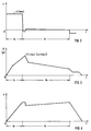
- the feed drive 2 should be as fast as possible so that, for example, the injection mold is filled well and little time is required. This high speed can only be achieved with very large forces. Power and speed requirements change during the injection process. At the beginning, the back pressure is relatively low and as much plastic as possible should be injected. Towards the end of the process and during the holding phase, a slow speed at high pressure is required. For the retraction of the screw 4, no great forces are required from the drive 2, which leads to a partially simplified construction of the toggle lever drive 2. In Figures 2 to 4 are the speed v s , the force F or the pressure P and the displacement path s of the process are plotted against time t in a diagram.
- the electromechanical feed drive 2 consists of a double toggle lever 8, a double ball screw 10, a displaceable support frame 12 and a three-phase servo motor 14.
- the double ball screw 10 with opposite thread is mounted on both sides in the support frame 12.
- the three-phase servomotor 14 drives the double ball screw 10 directly or by means of an additional gear.
- a toothed or V-belt drive is provided as an additional gear.
- the double ball screw 10 guides the symmetrically arranged toggle arms 16, 20 and 18, 22, respectively, the joints 24 and 26 of the two toggle levers 16, 20 and 18, 22 being connected to the threaded spindle 10 by means of a spindle nut 28 and 30 or a spindle adapter are.
- the ends of the long toggle lever arm 16 or 18 and the short toggle lever arm 20 or 22 facing away from the joint 24 or 26 are supported on cross members 32 or 34 and 36 or 38 by means of bearings 40 or 42 and 44 or 46.
- the cross members 32 and 34 are attached to the housing of the plastic injection molding machine and the cross members 36 and 38 are attached to the plasticizing screw 4.
- the lengths of the traverses 32 and 34 and 36 and 38 determine the projected distance (ab) of the support points of the toggle levers 16, 20 and 18, 22 to one another.
- the long toggle arm 16 or 18 preferably consists of two toggle arms, which are arranged spatially parallel. This allows the long and short toggle arms 16 and 20 or 18 and 22 to cross. In addition, this simplifies the mounting of the long toggle arm 16 or 18 on the crossmember 32 or 34, the forces acting on the bearings 40 and 42 canceling each other out. Furthermore, the load on the long toggle arms 16 and 18 is distributed over two spatially parallel toggle arms.
- the arrangement and the choice of suitable length ratios of the toggle levers adapt the force curve to the force requirement of the injection process, the force being able to be applied by a commercially available feed drive.
- the transmission ratio i K of the toggle lever or the overall transmission ratio i G is sufficient for example from about 2.5 at the beginning of the injection process to 10 at the end or during the holding pressure phase.
- the possible injection speed is high at first and then drops to about a third.
- a better force / speed ratio is generated compared to a direct conversion electromechanical feed drive. Due to the high rigidity of the system, the process can be controlled more precisely than with hydraulic feed drives.
- FIG. 5 shows the geometry of a toggle lever 16, 20 of the double toggle lever 8.
- the transmission ratio i K of the double knee lever 8 is obtained from with equation (1) is the gear ratio
- the toggle characteristic i K is a function of three independent variables, namely the length l1 of the long toggle arm 16, the length l2 of the short toggle arm 20 and the distance (a - b) of the support points of the long projected onto a axis of rotation r of the plasticizing screw 4 and the short toggle arm 16 and 20 (joints 40 and 42).
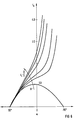
- the individual profiles of the transmission ratios i K are plotted in a diagram over the closing angle ⁇ , the variable l 1 changing according to the arrow A in a positive direction (larger).
- the individual profiles of the gear ratios i K are plotted in a diagram over the closing angle ⁇ , the variable l 2 changing in a positive direction (larger) in accordance with the arrows B and C.
- the individual profiles of the gear ratios i K are plotted in a diagram over the closing angle ⁇ , the variable (ab) changing in the positive direction (larger) according to the arrow D.
- the transmission ratio i K (s) of the toggle lever mechanism 2 to be dimensioned must not exceed the speed limit curves i max1 , ..., i max3 , since otherwise the maximum speed would be exceeded at a predetermined drive speed v ab (s).
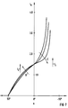
- FIG. 9 shows the overall transmission ratio i G by means of a broken line.
- the associated limit curves i max3 and i min3 '' show that the double ball screw has a pitch of 10 mm / rev.
- the overall ratio applies from 6 to 20 along the displacement path s or standardized path s *. Since such a ratio cannot be applied by a toggle lever system alone, an additional gear, for example a toothed or belt drive, is provided. This additional gearbox is able to change the gear ratio by exchanging pulleys, whereby a higher maximum injection speed can be achieved, provided that the power reserves of the drive have not been exhausted in the injection phase.
- ) With and to l Sp 600 mm.
- FIG. 10 shows the stroke h of the displaceable complex of three-phase servo motor 14 - gear - threaded spindle 10.
- the joint 24 of the toggle lever moves on a circular path with a radius equal to the length l 1 of the long toggle lever arm 16 around the bearing 40 in the cross member 32.
- the length l 1 of the long toggle lever 16 or 18 1200 mm and the length l 2 of the short toggle lever 20 or 22 900 mm have been chosen.
- the projected distance (a - b) of the support points of the toggle levers 16 and 20 or 18 and 22 is 150 mm and the value of the closing angle is -5 ° ⁇ ⁇ ⁇ 35 °.
- the three-phase servomotor 14 is a commercially available servomotor with a nominal output of 10.8 kW and a maximum speed of 6,000 rpm. been selected.
Landscapes
- Engineering & Computer Science (AREA)
- Manufacturing & Machinery (AREA)
- Mechanical Engineering (AREA)
- Injection Moulding Of Plastics Or The Like (AREA)
- Moulds For Moulding Plastics Or The Like (AREA)
- Transmission Devices (AREA)
Claims (10)
- Dispositif d'entraînement d'avance électromécanique (2) pour une vis de plastification (4) d'une machine de moulage de matière plastique par injection, constitué d'un moteur électrique et d'une transmission mécanique démultiplicatrice, caractérisé par le fait qu'on utilise comme transmission mécanique démultiplicatrice deux leviers coudés (8) à bras inégaux, fournissant un rapport de démultiplication (iK),
 (a-b) = distance projetée entre les points d'appui du levier coudé,α = angle de fermeture,l₁ = longueur du bras long (16,18) du levier coudé,l₂ = longueur du bras court (20,22) du levier coudé.et dont les bras longs (16,18) prennent appui sur le corps de la machine de moulage de matière plastique par injection et dont les bras courts (20,22) prennent appui sur la vis de plastification (4), et dont les deux articulations (24,26) sont reliées, chacune par l'intermédiaire d'un écrou de broche (28,30), à une broche filetée (10) double à billes montée des deux côtés au moyen d'un cadre de support (12) et possédant des filetages tournant dans des sens opposés, la broche filetée (10) double étant entraînée au moyen d'un servomoteur à courant triphasé (14).
 - Dispositif d'entraînement d'avance électronique (2) suivant la revendication 1, caractérisé par le fait que le rapport de transmission (iK(s)) des deux leviers coudés (8) est limité, en fonction d'un trajet de déplacement (s), par un rapport de transmission de vitesse (imax(s*)) et par un rapport de transmission de force (imin(s*)).
- Dispositif d'entraînement d'avance électromécanique (2) suivant la revendication 1, caractérisé par le fait qu'une transmission supplémentaire est prévue entre la broche filetée (10) double à billes et le servomoteur à courant triphasé (14).
- Dispositif d'entraînement d'avance électromécanique (2) suivant la revendication 1, caractérisé par le fait que le servomoteur à courant triphasé (14) est fixé au cadre de support (12).
- Dispositif d'entraînement d'avance électromécanique (2) suivant la revendication 1, caractérisé par le fait que le cadre de support (12) est monté mobile dans la direction du trajet de déplacement (s) de la vis de plastification (4).
- Dispositif d'entraînement d'avance électromécanique (2) suivant la revendication 1, caractérisé par le fait qu'il est prévu, comme servomoteur à courant triphasé (14), un moteur ayant une grande vitesse de rotation, un poids petit, un petit moment d'inertie et une grande surcharge admissible.
- Dispositif d'entraînement d'avance électromécanique (2) suivant la revendication 1, caractérisé par le fait que chacun des bras longs(16,18) des deux leviers coudés (8) est constitué de deux bras parallèles et distants dans l'espace.
- Dispositif d'entraînement d'avance électromécanique (2) suivant la revendication 3, caractérisé par le fait qu'il est prévu, comme transmission supplémentaire, un dispositif d'entraînement à courroie.
- Dispositif d'entraînement d'avance électromécanique (2) suivant la revendication 5, caractérisé par le fait que le décalage (h) du cadre de support (12) est déterminé par la relation suivante :

avec
- Dispositif d'entraînement d'avance électromécanique (2) suivant la revendication 1, caractérisé par le fait que la longueur (lsp) de la broche filetée (10) double à billes peut être déterminée en fonction de la géométrie des deux leviers coudés (8) conformément à la relation suivante :

avec

Priority Applications (3)
| Application Number | Priority Date | Filing Date | Title |
|---|---|---|---|
| DE90104738T DE59003971D1 (de) | 1990-03-13 | 1990-03-13 | Elektromechanischer Vorschubantrieb für eine Plastifizierschnecke einer Kunststoffspritzgiessmaschine. |
| EP90104738A EP0447570B1 (fr) | 1990-03-13 | 1990-03-13 | Dispositif d'entraînement d'avance électromécanique pour une vis de plastification d'une machine à mouler les matières plastiques par injection |
| AT90104738T ATE98926T1 (de) | 1990-03-13 | 1990-03-13 | Elektromechanischer vorschubantrieb fuer eine plastifizierschnecke einer kunststoffspritzgiessmaschine. |
Applications Claiming Priority (1)
| Application Number | Priority Date | Filing Date | Title |
|---|---|---|---|
| EP90104738A EP0447570B1 (fr) | 1990-03-13 | 1990-03-13 | Dispositif d'entraînement d'avance électromécanique pour une vis de plastification d'une machine à mouler les matières plastiques par injection |
Publications (2)
| Publication Number | Publication Date |
|---|---|
| EP0447570A1 EP0447570A1 (fr) | 1991-09-25 |
| EP0447570B1 true EP0447570B1 (fr) | 1993-12-22 |
Family
ID=8203745
Family Applications (1)
| Application Number | Title | Priority Date | Filing Date |
|---|---|---|---|
| EP90104738A Expired - Lifetime EP0447570B1 (fr) | 1990-03-13 | 1990-03-13 | Dispositif d'entraînement d'avance électromécanique pour une vis de plastification d'une machine à mouler les matières plastiques par injection |
Country Status (3)
| Country | Link |
|---|---|
| EP (1) | EP0447570B1 (fr) |
| AT (1) | ATE98926T1 (fr) |
| DE (1) | DE59003971D1 (fr) |
Families Citing this family (2)
| Publication number | Priority date | Publication date | Assignee | Title |
|---|---|---|---|---|
| DE4327710C1 (de) * | 1993-08-18 | 1994-09-08 | Kloeckner Ferromatik Desma | Einspritzaggregat |
| CN109909530A (zh) * | 2018-12-31 | 2019-06-21 | 江苏一重数控机床有限公司 | 一种焊缝铣削机构 |
Family Cites Families (3)
| Publication number | Priority date | Publication date | Assignee | Title |
|---|---|---|---|---|
| DE682116C (de) * | 1935-06-30 | 1939-10-07 | Emil Hempel | Antrieb fuer Spritzmaschinen fuer organische, in der Waerme formbare Massen |
| CA1196458A (fr) * | 1981-10-08 | 1985-11-12 | Yoshihiko Yamazaki | Machine a mouler par injection |
| JPS62128724A (ja) * | 1985-11-30 | 1987-06-11 | Fanuc Ltd | 射出駆動装置 |
-
1990
- 1990-03-13 DE DE90104738T patent/DE59003971D1/de not_active Expired - Fee Related
- 1990-03-13 EP EP90104738A patent/EP0447570B1/fr not_active Expired - Lifetime
- 1990-03-13 AT AT90104738T patent/ATE98926T1/de not_active IP Right Cessation
Also Published As
| Publication number | Publication date |
|---|---|
| EP0447570A1 (fr) | 1991-09-25 |
| ATE98926T1 (de) | 1994-01-15 |
| DE59003971D1 (de) | 1994-02-03 |
Similar Documents
| Publication | Publication Date | Title |
|---|---|---|
| EP0363394B1 (fr) | Unite de fixation de precision pour machines de moulage par injection | |
| DE69601951T2 (de) | Spritzvorrichtung für eine elektrische Spritzgiessmaschine | |
| AT507109B1 (de) | Einspritzeinheit für eine spritzgiessmaschine | |
| EP0674985B1 (fr) | Unité de fermeture de moule pour une machine à mouler par injection et procédé pour son opération | |
| EP0837764B1 (fr) | Procede pour la regulation ou la commande d'une presse d'injection | |
| DE69032817T2 (de) | Antriebsanordnung für eine Spritzgiessmaschine | |
| DE69607999T2 (de) | Auswurfvorrichtung | |
| EP2629954A1 (fr) | Machine de moulage par injection comportant au moins deux mécanismes de genouillères | |
| EP0627289B1 (fr) | Unité d'injection pour machine d'injection de matières plastiques | |
| DE19852513A1 (de) | Einspritzvorrichtung für eine Spritzgußmaschine | |
| DE19932741C2 (de) | Verfahren und Vorrichtung zum Schließen und Öffnen des Werkzeugs einer Kunststoffverarbeitungsmaschine | |
| DE4409822C2 (de) | Antrieb für wenigstens eine linear bewegbare Achse einer Spritzgießmaschine | |
| EP3655225B1 (fr) | Unite de fermeture de moule pour machine de moulage par injection | |
| DE69901903T2 (de) | Elektrische Injektionsvorrichtung für Spritzgiesspressen für Kunststoffmaterialien | |
| EP3529029B1 (fr) | Unité de fermeture d'un moule à réglage en hauteur du moule, et procédé permettant de l'actionner | |
| EP0447570B1 (fr) | Dispositif d'entraînement d'avance électromécanique pour une vis de plastification d'une machine à mouler les matières plastiques par injection | |
| DE102020124882B4 (de) | Phaseneinstellvorrichtung und Phaseneinstellverfahren | |
| DE4411650C2 (de) | Formschließeinheit für eine Spritzgießmaschine | |
| EP0639444B1 (fr) | Unité d'injection | |
| DE602004012278T2 (de) | Spritzgiessvorrichtung und verfahren zur verwendung solch einer spritzgiessvorrichtung | |
| DE102007027212A1 (de) | Elektrische Spritzgußeinrichtung für Kunststoff-Spritzgußpressen | |
| EP1211043B1 (fr) | Méthode d'utilisation d'une unité d'injection d'une machine à moulage par injection | |
| DE19511917C2 (de) | Verfahren zum Betreiben einer Formschließeinheit für eine Spritzgießmaschine | |
| AT403136B (de) | Vorrichtung zum schliessen von formen einer spritzgiessmaschine | |
| DE202011000322U1 (de) | Spritzgießvorrichtung |
Legal Events
| Date | Code | Title | Description |
|---|---|---|---|
| PUAI | Public reference made under article 153(3) epc to a published international application that has entered the european phase |
Free format text: ORIGINAL CODE: 0009012 |
|
| 17P | Request for examination filed |
Effective date: 19901205 |
|
| AK | Designated contracting states |
Kind code of ref document: A1 Designated state(s): AT BE CH DE DK ES FR GB GR IT LI LU NL SE |
|
| RBV | Designated contracting states (corrected) |
Designated state(s): AT BE CH DE FR GB IT LI |
|
| 17Q | First examination report despatched |
Effective date: 19930312 |
|
| GRAA | (expected) grant |
Free format text: ORIGINAL CODE: 0009210 |
|
| AK | Designated contracting states |
Kind code of ref document: B1 Designated state(s): AT BE CH DE FR GB IT LI |
|
| PG25 | Lapsed in a contracting state [announced via postgrant information from national office to epo] |
Ref country code: IT Free format text: LAPSE BECAUSE OF FAILURE TO SUBMIT A TRANSLATION OF THE DESCRIPTION OR TO PAY THE FEE WITHIN THE PRE;WARNING: LAPSES OF ITALIAN PATENTS WITH EFFECTIVE DATE BEFORE 2007 MAY HAVE OCCURRED AT ANY TIME BEFORE 2007. THE CORRECT EFFECTIVE DATE MAY BE DIFFERENT FROM THE ONE RECORDED.SCRIBED TIME-LIMIT Effective date: 19931222 Ref country code: FR Effective date: 19931222 Ref country code: BE Effective date: 19931222 Ref country code: GB Effective date: 19931222 |
|
| REF | Corresponds to: |
Ref document number: 98926 Country of ref document: AT Date of ref document: 19940115 Kind code of ref document: T |
|
| REF | Corresponds to: |
Ref document number: 59003971 Country of ref document: DE Date of ref document: 19940203 |
|
| PGFP | Annual fee paid to national office [announced via postgrant information from national office to epo] |
Ref country code: AT Payment date: 19940223 Year of fee payment: 5 |
|
| EN | Fr: translation not filed | ||
| PGFP | Annual fee paid to national office [announced via postgrant information from national office to epo] |
Ref country code: DE Payment date: 19940519 Year of fee payment: 5 |
|
| PGFP | Annual fee paid to national office [announced via postgrant information from national office to epo] |
Ref country code: CH Payment date: 19940617 Year of fee payment: 5 |
|
| GBV | Gb: ep patent (uk) treated as always having been void in accordance with gb section 77(7)/1977 [no translation filed] |
Effective date: 19931222 |
|
| PLBE | No opposition filed within time limit |
Free format text: ORIGINAL CODE: 0009261 |
|
| STAA | Information on the status of an ep patent application or granted ep patent |
Free format text: STATUS: NO OPPOSITION FILED WITHIN TIME LIMIT |
|
| 26N | No opposition filed | ||
| PG25 | Lapsed in a contracting state [announced via postgrant information from national office to epo] |
Ref country code: AT Effective date: 19950313 |
|
| PG25 | Lapsed in a contracting state [announced via postgrant information from national office to epo] |
Ref country code: LI Effective date: 19950331 Ref country code: CH Effective date: 19950331 |
|
| REG | Reference to a national code |
Ref country code: CH Ref legal event code: PL |
|
| PG25 | Lapsed in a contracting state [announced via postgrant information from national office to epo] |
Ref country code: DE Effective date: 19951201 |