EP0447529B1 - Procede de mesure de la taille et de la vitesse de particules spheriques a l'aide de la phase et de l'intensite de lumiere diffusee - Google Patents
Procede de mesure de la taille et de la vitesse de particules spheriques a l'aide de la phase et de l'intensite de lumiere diffusee Download PDFInfo
- Publication number
- EP0447529B1 EP0447529B1 EP90914982A EP90914982A EP0447529B1 EP 0447529 B1 EP0447529 B1 EP 0447529B1 EP 90914982 A EP90914982 A EP 90914982A EP 90914982 A EP90914982 A EP 90914982A EP 0447529 B1 EP0447529 B1 EP 0447529B1
- Authority
- EP
- European Patent Office
- Prior art keywords
- amplitude
- theoretical value
- phase
- size
- particles
- Prior art date
- Legal status (The legal status is an assumption and is not a legal conclusion. Google has not performed a legal analysis and makes no representation as to the accuracy of the status listed.)
- Expired - Lifetime
Links
- 238000000034 method Methods 0.000 title claims description 55
- 239000012798 spherical particle Substances 0.000 title description 6
- 239000002245 particle Substances 0.000 claims abstract description 107
- 238000004513 sizing Methods 0.000 claims abstract description 11
- 238000005259 measurement Methods 0.000 claims description 51
- 238000001514 detection method Methods 0.000 claims description 11
- 230000003247 decreasing effect Effects 0.000 claims description 3
- 238000002356 laser light scattering Methods 0.000 claims description 3
- 230000001427 coherent effect Effects 0.000 abstract description 2
- 238000000149 argon plasma sintering Methods 0.000 description 15
- 238000009826 distribution Methods 0.000 description 12
- 230000010363 phase shift Effects 0.000 description 9
- 230000035945 sensitivity Effects 0.000 description 7
- 238000013459 approach Methods 0.000 description 6
- 238000004364 calculation method Methods 0.000 description 5
- 238000004458 analytical method Methods 0.000 description 4
- 230000000694 effects Effects 0.000 description 4
- 238000005305 interferometry Methods 0.000 description 4
- 230000003287 optical effect Effects 0.000 description 4
- 239000007921 spray Substances 0.000 description 3
- 238000004599 local-density approximation Methods 0.000 description 2
- 230000007246 mechanism Effects 0.000 description 2
- 238000010587 phase diagram Methods 0.000 description 2
- 238000012545 processing Methods 0.000 description 2
- 238000011160 research Methods 0.000 description 2
- 238000000926 separation method Methods 0.000 description 2
- 238000012360 testing method Methods 0.000 description 2
- 241000209035 Ilex Species 0.000 description 1
- 206010043458 Thirst Diseases 0.000 description 1
- 239000005427 atmospheric aerosol Substances 0.000 description 1
- 230000008033 biological extinction Effects 0.000 description 1
- 230000003139 buffering effect Effects 0.000 description 1
- 238000002485 combustion reaction Methods 0.000 description 1
- 230000010485 coping Effects 0.000 description 1
- 238000010586 diagram Methods 0.000 description 1
- 238000002474 experimental method Methods 0.000 description 1
- 239000012530 fluid Substances 0.000 description 1
- 239000000446 fuel Substances 0.000 description 1
- 230000002262 irrigation Effects 0.000 description 1
- 238000003973 irrigation Methods 0.000 description 1
- 238000004519 manufacturing process Methods 0.000 description 1
- 238000000691 measurement method Methods 0.000 description 1
- 239000000575 pesticide Substances 0.000 description 1
- 230000010287 polarization Effects 0.000 description 1
- 230000005514 two-phase flow Effects 0.000 description 1
- 238000012795 verification Methods 0.000 description 1
Images


Classifications
-
- G—PHYSICS
- G01—MEASURING; TESTING
- G01N—INVESTIGATING OR ANALYSING MATERIALS BY DETERMINING THEIR CHEMICAL OR PHYSICAL PROPERTIES
- G01N15/00—Investigating characteristics of particles; Investigating permeability, pore-volume or surface-area of porous materials
- G01N15/02—Investigating particle size or size distribution
- G01N15/0205—Investigating particle size or size distribution by optical means
- G01N15/0211—Investigating a scatter or diffraction pattern
- G01N2015/0216—Investigating a scatter or diffraction pattern from fluctuations of diffraction pattern
-
- G—PHYSICS
- G01—MEASURING; TESTING
- G01N—INVESTIGATING OR ANALYSING MATERIALS BY DETERMINING THEIR CHEMICAL OR PHYSICAL PROPERTIES
- G01N15/00—Investigating characteristics of particles; Investigating permeability, pore-volume or surface-area of porous materials
- G01N15/10—Investigating individual particles
- G01N15/14—Optical investigation techniques, e.g. flow cytometry
- G01N15/1434—Optical arrangements
- G01N2015/1447—Spatial selection
- G01N2015/145—Spatial selection by pattern of light, e.g. fringe pattern
Definitions
- the present invention relates to particle size and velocity measurements using scattered laser light detection and, more specifically, relates to such measurements utilizing the Doppler difference frequency, relative signal phase, and intensity of the scattered light.
- Particle size is determinable from the intensity of the light scattered by particles. The higher the intensity of scattered light, the larger the particle size.
- the particle size is computed by assuming that a particle scatters light in proportion to the diameter of the particle squared (d 2 ).
- d 2 the diameter of the particle squared
- particle size measurements which use the intensity of scattered light to determine particle size are quite imprecise because there are a number of unknown parameters such as the incident intensity on the particle, the crosssection of the incident laser light and the particle trajectory through the laser beam.
- Another method based on light scattering interferometry referred to as visibility, has been used to measure spherical particles, drops, bubbles, or the like. This method is described by William D. Bachalo, in an article entitled, “Method for Measuring the Size and Velocity of Spheres by Dual-Beam Light-Scatter Interferometry", Applied Optics , Vol. 19, February 1, 1980 and in U.S. Patent No. 4,329,054 which issued on May 11, 1982.
- the spatial period of the interference fringe pattern generated by a spherical particle, drop, bubble, or the like as it passes through a sample volume defined by the intersection of crossed laser beams is used in determining the particle size and velocity.
- Several methods have been devised for measuring the spatial period of the fringe pattern.
- the fringe pattern was integrated over the receiver lens aperture to obtain the spacing or spatial period of the fringe pattern.
- the signal visibility which resulted could then be related to the particle size.
- This method has drawbacks since the dynamic range of the system was limited, and the combined light scattering by the mechanisms of refraction and reflection produced uncertainties in the measurements.
- other particles passing through the crossed beams produce extinction pulses that tend to distort the signals and hence, compromise the measurement accuracy.
- phase/doppler method An alternative approach to the visibility method, referred to as the "phase/doppler method", was described by F. Durst and M. Zare in a paper entitled, “Laser Doppler Measurements in Two-Phase Flows", Proceedings of the LDA Symposium, Copenhagen, 1975.
- the authors provided a basic analysis using a simple geometrical approach to show that the shape and spacing of the fringes formed by the scattered light through reflection and refraction are functions of the angle between the incident laser beams, their wavelength, as well as the direction of light collection and particle diameter.
- spherical particles could be measured using a double photo-detector apparatus, they later recognized that size measurements required that the distance between the photo-detectors be matched to the expected fringe spacing produced by the scattered light. They concluded that the method was not practical for particle field measurements.
- This method has the disadvantage of relatively low scattering intensity, lower sensitivity to particle size and inconvenience in applications requiring traversing the sample volume with restricted optical access. Often, backscatter light detection is desirable. Although off-axis backscatter detection has been demonstrated as a viable configuration, errors can occur as a result of the multiple component scattering of reflection and refraction.
- the problem is exacerbated when using highly focused laser beams having Gaussian beam intensity distributions.
- Highly focused beams are required to reduce the sample volume size when coping with high particle number densities. For example, at a light detection angle of 30° with the appropriate polarization, the scattered coefficient for refraction is approximately 80 times that for reflection.
- the relative incident intensities can be such that the light scattering by reflection and refraction are nearly equal. Because the sign of the phase shift for the fringe pattern produced by reflected light is opposite to that produced by refracted light, the fringes produced by reflection move in the opposite direction.
- the present invention discloses a method to overcome this source of error and to provide an alternative means to test the measurements for their accuracy.
- the method can provide an alternate means to allow the measurements over several fringes (Nx2 ⁇ ) without ambiguity, and without using additional phase measurements which can complicate the signal processing.
- a method is also described for measuring the sample volume cross section which is known to vary with particle size.
- a laser generation means is provided for generating a pair of coherent laser beams and means are provided to change the separation, intersection angle, and focused diameter of the beams. These beams are directed along an axis, and are caused to cross the axis at a given angle to define an interference pattern constituting a sample volume.
- a collection apparatus for sensing the light scattered by particles, droplets, bubbles, or the like travelling through the sample volume is provided. In the presently preferred embodiment, the collection apparatus is disposed at preferred off-axis angles including off-axis backscatter with the angle predetermined, and the angle defined by the direction of beam propagation.
- the collected scattered light is directed onto photo-detectors which are coupled to a signal phase determining means, for measuring the relative phase between the signals produced by each photo-detector and a signal amplitude determining means to measure the relative amplitude of the signals produced as the particle, drop, bubble, or the like passes through the sample volume.
- Sizing means are coupled to the signal phase and amplitude determination means for determining the size of the particle, drop, bubble, or the like from phase and amplitude changes in the received signals.
- the present invention determines particle size by the phase of the scattered light signals but overcomes problems associated with this technique, that is, the ambiguity due to the combined light scattering effect by the mechanisms of refraction and reflection.
- the ambiguity is reduced by examining the amplitude of the scattered light signals to ensure that the amplitudes fall within a certain range of signal amplitudes considered to be reliable. Signals not falling within prescribed maximum and minimum values are rejected from the measurement calculations leaving only those signals which result in meaningful calculations.
- FIGURE 1 is a diagrammatical representation of the presently preferred embodiment of the invention.
- FIGURE 2 is a schematic illustrating a Gaussian intensity laser beam incident on a sphere.
- FIGURE 3 is a table illustrating theoretical amplitude values computed using a geometric technique and their corresponding particle sizes.
- FIGURE 4 is a logarithmic graph illustrating the theoretical amplitude values computed for particle size classes using the Lorenz-Mie theory.
- FIGURE 5 is a graph of signal voltage variation versus particle size.
- FIGURE 6 schematically illustrates the phase for particle sizing over multiple fringe cycles.
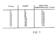
- FIGURE 7 is a table illustrating phase and amplitude values for classes of particle size.
- FIGURE 8 is a graph of phase and corresponding size distribution when particle size exceeds selected range.
- FIGURE 9 is a graph of phase and corresponding size distribution after size range adjustment.
- FIGURE 10 schematically illustrates the use of redundant phase measurements to measure greater than 360° of phase shift at high sensitivity.
- particles An apparatus and method for determining the size and velocity of particles, droplets, bubbles, or the like (hereinafter sometimes collectively referred to as "particles") using laser light scattering is disclosed.
- particles An apparatus and method for determining the size and velocity of particles, droplets, bubbles, or the like (hereinafter sometimes collectively referred to as "particles") using laser light scattering.
- numerous details are set forth such as specific wavelengths, angles, frequencies, etc. in order to provide a thorough understanding of the present invention.
- the invention may be practiced without these specific details.
- well known components, structures and electrical processing means have not been described in detail in order not to obscure the present invention unnecessarily.
- the apparatus for determining the size and velocity of particles includes a sample volume denoted generally by the numeral 16.
- the sample volume 16 is defined as the overlap region of a first laser beam 18 and a second laser beam 20 which are caused to cross at an angle gamma with respect to an axis defined through the intersection of the two beams 18 and 20.
- the laser beams employed by the present invention are generated in the preferred embodiment by a single laser 25.
- the primary beam 28 generated by laser 25 is passed through a beam splitter 30, thereby forming first and second beams 32 and 34, respectively.
- Beams 32 and 34 are reflected off of reflectors 36 and 38, and are passed through a focussing lens 40 which causes the beams to cross at the desired angle and form sample volume 16. It should be noted however, that reflectors 36 and 38 are not necessary to practice this invention and an "in-line" system accomplishes the same result.
- the beams have been broken and then shown in enlarged form in the region of the sample volume.
- Particles passing through the sample volume 16 scatter light from each beam and the scattered light interferes to form interference fringe patterns in the space surrounding the particle.
- the phase of the scattered light forms the interference fringe pattern at a specific spatial frequency.
- This spatial frequency is inversely proportional to the particle diameter.
- the scattered light intensity and hence, the signal amplitude depends on the particle diameter squared, the incident intensity as well as other parameters that are determined by the optical geometry.
- the scattered light is sensed by a collection apparatus which includes lenses 46 and 48, which focus the light onto photo-detectors 50.
- Photo-detectors 50 are coupled through amplifiers 52 to phase detection means 54 and sizing means 56.
- a circuit means 57 is coupled to the sizing means 56, to determine the change in the effective cross-section of the sample volume 16 due to size variations of particles, droplets and the like passing through the interference pattern 42, as will be described below.
- Figure 2 is a schematic illustration of the laser beam with Gaussian intensity incident on a particle or droplet in the shape of a sphere.
- Phase measurements as described by the inventor, W. Bachalo in U.S. Patent No. 4,540,283 provide measurements of the particle diameter.
- the Gaussian intensity distribution of the laser beam operating in the fundamental mode (TEM ⁇ ) and the random particle trajectories through the beam, the combined light scattering by reflection and refraction can produce significant error. This problem occurs, for example, for particles passing on trajectories as illustrated in Figure 2 .
- the light intensity scattered by refraction is approximately 80 times that scattered by reflection.
- the difference can be much less due to the nonuniform beam intensity with the greater incident intensity falling on the point reflecting light to the detector.
- the interference fringe pattern is no longer sinusoidal, but becomes a complex superposition of several spatial frequency components.
- the interference fringes produced by reflection also move in the opposite direction to the fringes produced by refraction. This can lead to large measurement errors.
- the intensity or signal amplitude information is used as a means of preventing gross errors due to the effect of the aforementioned mixed scattering components that occurs for certain particle trajectories through the beam. More specifically, the amplitude information is used to determine the range of signal values considered reliable enough to result in accurate calculations. If the amplitude measurements falls outside the range of signal values considered to be reliable, the signal measurements (phase and amplitude) are rejected and not utilized in the computation of the particle size.
- I/I o 1/e 2
- this approach has the advantage of reducing the size of the sample volume 16 and decreasing the number of signals to be processed that will ultimately be rejected. Particles of a given size passing on all trajectories through the beam will produce a range of light scattering intensities of 1/e ⁇ I/I max ⁇ 1.
- the range of reliable signal values is determined empirically by measuring the range of amplitude values (also referred to as intensity values) for a known particle size class.
- the range of reliable signal values may also be derived from the calculation of the theoretical amplitude values for a range of classes of particle size.
- a range of acceptable amplitude values is then determined by computing an upper limit above the theoretical value and a lower limit below the theoretical value.
- the theoretical amplitude values may be determined by assuming that a particle scatters light in proportion to the diameter of the particle squared (d 2 ).
- An exemplary table containing the theoretical values computed is shown in Figure 3 .
- the values can be computed using the Lorenz-Mie theory which is computationally intensive but produces accurate results for particle sizes less than 3 microns, where the geometric calculation (d 2 ) breaks down.
- a logarithmic graph showing the intensity values (volts) for corresponding particle diameters (um) is illustrated in Figure 4 .
- the theoretical values may be computed as the signal value measurements are taken or may be computed for a range of particle size classes and stored in lookup tables for quick and easy reference.
- the upper limit may be the theoretical value computed. Preferably, the upper limit is slightly greater than, for example, 0-.25 volts, the theoretical value to provide a buffering zone.
- the lower limit on the accepted light scattering intensity may be selected depending upon the requirements for measurement accuracy, the possibility for mixed component light scattering, and other considerations. For example, if as described above, the Gaussian beam is clipped at 1/e, particles of a given size passing on all trajectories through the beam will produce a range of light scattering intensities of 1/e ⁇ I/I max ⁇ 1. Thus, the uncertainty in the particle diameter due to particle trajectory through the clipped Gaussian beam is 1/e to 1 or 0.368 to 1, and the lower limit would preferably be set to approximately 1/3 of the theoretical value.
- FIG. 5 An example of the diagram of acceptable scattered intensities is shown in Figure 5 .
- the detector gain is set automatically such that the maximum signal amplitude for each particle size class falls on the d 2 curve passing through the maximum allowable signal.
- the gain is set with the assumption that the phase Doppler method measures the size accurately of most particles passing through the center of the Gaussian beam. This assumption has been shown to be correct by experiment.
- An acceptable error limit which functions as a buffer, is set on the maximum value shown as the dashed curve marked "upper” on Figure 5 .
- the dashed curve marked "lower limit" on Figure 5 can be adjusted to select the range of scattered intensities over which particles will be accepted for each size class.
- the acceptable limits for particle size classes may be computed as the measurements are taken or are preferably computed prior to the measurements and stored in a lookup table for quick reference.
- the curve fitting procedure When the intensity or signal amplitude is used to validate the measurements obtained from the phase method, the curve fitting procedure must be modified to allow for the lower limit of signal amplitude accepted which will manifest as a lower limit of the sample volume width. This effect can be predicted easily using the selected lower cut-off value of the signal amplitude.
- the signal amplitude information may also be used to allow measurements of phase shifts that exceed 2 ⁇ (360°) using only one pair of detectors or in conjunction with the method using multiple pairs of detectors.
- the limitation on the number of cycles of signal phase difference over which the method can be used depends on the range of the incident intensities accepted. That is, since the laser beam has a Gaussian beam intensity distribution, the incident intensity will vary based upon the particle trajectory. However, the beam intensity distribution can be clipped to limit the range of signal amplitudes for each particle size class.
- Figure 6 shows the phase diagram for a range of particle sizes over more than one phase difference cycle. In the example of Figure 6 , the phase is shown as varying over two cycles (4 ⁇ or 720°).
- the dimensionless signal amplitude for a particle producing a 360° phase shift would be approximately 0.25 whereas the dimensionless signal amplitude for a particle producing a phase shift of 720° would be 1.0.
- the signal amplitudes can be used to reliably identify the cycle of the phase measurement ( ⁇ or ⁇ + 360) and, hence, the size of the particle.
- the phase information and corresponding amplitude information may be computed for each measurement or, alternatively, may be calculated ahead of time and incorporated into a lookup table for easy reference.
- photo-detectors 52 comprise at least two photo-detector's 120 and 125.
- the phase measurements can be extended over several cycles of phase (n x 2 ⁇ ) where n is the number of cycles.
- the pair of detectors spaced close together will limit the upper size of the particle that can be measured without ambiguity. That is, the fringe spacing can be less than the closest spaced detectors (detectors 120 and 125 on Figure 10 .
- Proper selection of the detector spacings can be used to perform measurements with the phase varying more than 360° on each detector pair.
- the measurements can be compared to evaluate over which cycle each measurement occurred.
- the redundant measurements can then be further compared to estimate the reliability of each measurement.
- the present invention includes a phase shifting method which splits the signals from the detectors and shifts the phase of one of the signals from each pair by 180°. Circuitry is then used to determine when the signal phase differences approach 360°. This can be recognized from the fact that the difference between the corresponding signals on the other pair will be near 180° which can be done accurately. The potentially large errors produced by attempting the measurement near 360° are avoided.
Landscapes
- Chemical & Material Sciences (AREA)
- Dispersion Chemistry (AREA)
- Physics & Mathematics (AREA)
- Health & Medical Sciences (AREA)
- Life Sciences & Earth Sciences (AREA)
- Analytical Chemistry (AREA)
- Biochemistry (AREA)
- General Health & Medical Sciences (AREA)
- General Physics & Mathematics (AREA)
- Immunology (AREA)
- Pathology (AREA)
- Length Measuring Devices By Optical Means (AREA)
- Investigating Or Analysing Materials By Optical Means (AREA)
Abstract
Claims (25)
- Dans un dispositif pour mesurer des paramètres associés à des particules, gouttelettes et similaires utilisant des premier et second faisceaux laser gaussiens (32, 34) dont le croisement est provoqué afin d'établir une figure d'interférence formant un volume d'échantillonnage (16), un procédé pour détecter des erreurs dues au mélange d'éléments dans la lumière diffusée par lesdites particules, gouttelettes et similaires passant à travers ladite figure d'interférence comprenant les étapes consistant à:(a) générer lesdits premier et second faisceaux laser gaussiens (32, 34) et diriger lesdits faisceaux pour qu'ils se croisent avec un angle connu de manière à former ledit volume d'échantillonnage (16);(b) capter (46, 48, 50) ladite lumière diffusée par lesdites particules, gouttelettes et similaires passant à travers ledit volume d'échantillonnage (16) et déterminer (54) la phase de ladite lumière diffusée;(c) déterminer (56) la taille desdites particules, gouttelettes et similaires à partir de la phase de ladite lumière diffusée;(d) déterminer l'amplitude de ladite lumière diffusée et comparer ladite amplitude à des limites d'amplitude supérieure et inférieure prédéfinies pour la taille de particule, de telle sorte que, si ladite amplitude déterminée se trouve en dehors desdites limites, une erreur est détectée et ladite mesure est considérée comme étant non valable.
- Procédé selon la revendication 1, dans lequel ladite amplitude est en outre comparée à des valeurs d'angle de phase mémorisées dans une table à consulter, ladite table fournissant un angle de phase correspondant pour une amplitude entrée, et il est déterminé si ladite amplitude correspond à un angle de phase supérieur à 2π.
- Procédé selon la revendication 1, dans lequel lesdites limites d'amplitude supérieure et inférieure sont mémorisées dans une table à consulter pour chaque catégorie de taille desdites particules, gouttelettes et similaires
- Procédé selon la revendication 1, dans lequel ladite limite supérieure est déterminée en calculant une valeur théorique pour la catégorie de taille de la taille de particule déterminée, et en augmentant la valeur théorique d'une quantité prédéterminée correspondant à une zone tampon.
- Procédé selon la revendication 4, dans lequel la valeur théorique est calculée en utilisant la théorie de Lorenz-Mie.
- Procédé selon la revendication 4, dans lequel la valeur théorique est calculée en utilisant une technique géométrique qui suppose que l'amplitude du signal est égale au carré du diamètre de particule.
- Procédé selon la revendication 4 dans lequel la quantité prédéterminée se trouve dans une plage allant de 0 à 0,25 volts.
- Procédé selon la revendication 1, dans lequel ladite limite inférieure est déterminée en calculant une valeur théorique pour la catégorie de taille de la taille de particule déterminée, et en diminuant la valeur théorique d'une quantité prédéterminée.
- Procédé selon la revendication 8, dans lequel la valeur théorique est calculée en utilisant la théorie de Lorenz-Mie.
- Procédé selon la revendication 8, dans lequel la valeur théorique est calculée en utilisant une technique géométrique qui suppose que l'amplitude du signal est égale au carré du diamètre de particule.
- Procédé selon la revendication 8, dans lequel la quantité prédéterminée est approximativement égale à un tiers de la valeur théorique.
- Procédé selon la revendication 1, dans lequel ladite étape de captage comprend la détection de ladite lumière diffusée en utilisant deux photodétecteurs espacés l'un de l'autre ou plus.
- Procédé selon la revendication 1, caractérisé en ce que lesdits éléments mélangés comprennent de la lumière réfléchie par les particules, gouttelettes et similaires et de la lumière réfractée à travers lesdites particules, gouttelettes et similaires.
- Dans un système pour mesurer des paramètres associés à des particules, gouttelettes et similaires utilisant la diffusion par faisceau laser, un appareil pour détecter des erreurs dues au mélange d'éléments dans ladite diffusion, comprenant:un moyen de génération laser (25) pour générer des premier et second faisceaux laser gaussiens (32, 34) et diriger lesdits faisceaux pour qu'ils se croisent de manière à former un volume d'échantillonnage (16);un moyen de captage (46, 48, 50) pour capter la lumière diffusée par lesdites particules, gouttelettes et similaires passant à travers ledit volume d'échantillonnage (16), et convertir ladite lumière diffusée en signaux électriques:un moyen de détection de phase (54) connecté au dit moyen de captage pour déterminer la phase et l'amplitude desdits signaux;un moyen de détermination de taille (56) connecté au dit moyen de détection de phase (54) pour déterminer la taille desdites particules, gouttelettes et similaires à partir de la phase desdits signaux, ledit moyen de détermination de taille (56) comparant en outre ladite amplitude à des limites d'amplitude supérieure et inférieure prédéfinies pour la taille de particule, de telle sorte que, si ladite amplitude se trouve en dehors desdites limites, une erreur est détectée et ladite mesure est considérée comme étant non valable.
- Dispositif selon la revendication 14, dans lequel ledit moyen de détermination de taille (56) compare en outre ladite amplitude à des valeurs d'angle de phase mémorisées dans un moyen formant table à consulter connecté au dit moyen de détermination de taille (56), ledit moyen formant table à consulter fournissant un angle de phase correspondant pour une amplitude entrée, et il est déterminé si ladite amplitude correspond à un angle de phase supérieur à 2π.
- Dispositif selon la revendication 14, dans lequel lesdites limites d'amplitude supérieure et inférieure sont mémorisées dans une table à consulter pour chaque catégorie de taille desdites particules, gouttelettes et similaires.
- Dispositif selon la revendication 14, dans lequel ladite limite supérieure est déterminée en calculant une valeur théorique pour la catégorie de taille de la taille de particule déterminée, et en augmentant la valeur théorique d'une quantité prédéterminée correspondant à une zone tampon.
- Dispositif selon la revendication 17, dans lequel la valeur théorique est calculée en utilisant la théorie de Lorenz-Mie.
- Dispositif selon la revendication 17, dans lequel la valeur théorique est calculée en utilisant une technique géométrique qui suppose que l'amplitude du signal est égale au carré du diamètre de particule.
- Dispositif selon la revendication 17 dans lequel la quantité prédéterminée se trouve dans une plage allant de 0 à 0,25 volts.
- Dispositif selon la revendication 14, dans lequel ladite limite inférieure est déterminée en calculant une valeur théorique pour la catégorie de taille de la taille de particule déterminée, et en diminuant la valeur théorique d'une quantité prédéterminée.
- Dispositif selon la revendication 21, dans lequel la valeur théorique est calculée en utilisant la théorie de Lorenz-Mie.
- Dispositif selon la revendication 21, dans lequel la valeur théorique est calculée en utilisant une technique géométrique qui suppose que l'amplitude du signal est égale au carré du diamètre de particule.
- Dispositif selon la revendication 21, dans lequel la quantité prédéterminée est approximativement égale à un tiers de la valeur théorique.
- Dispositif selon la revendication 14, dans lequel ledit moyen de captage détecte ladite lumière diffusée en utilisant deux photodétecteurs espacés l'un de l'autre ou plus.
Priority Applications (1)
| Application Number | Priority Date | Filing Date | Title |
|---|---|---|---|
| EP96110532A EP0737854B1 (fr) | 1989-10-03 | 1990-10-02 | Procédé et appareil pour mesurer la variation de section d'un volume contenant des échantillons défini par deux rayons laser croises |
Applications Claiming Priority (3)
| Application Number | Priority Date | Filing Date | Title |
|---|---|---|---|
| US416519 | 1989-10-03 | ||
| US07/416,519 US4986659A (en) | 1988-02-29 | 1989-10-03 | Method for measuring the size and velocity of spherical particles using the phase and intensity of scattered light |
| PCT/US1990/005615 WO1991005236A1 (fr) | 1989-10-03 | 1990-10-02 | Procede de mesure de la taille et de la vitesse de particules spheriques a l'aide de la phase et de l'intensite de lumiere diffusee |
Related Child Applications (2)
| Application Number | Title | Priority Date | Filing Date |
|---|---|---|---|
| EP96110532.7 Division-Into | 1990-10-02 | ||
| EP96110532A Division EP0737854B1 (fr) | 1989-10-03 | 1990-10-02 | Procédé et appareil pour mesurer la variation de section d'un volume contenant des échantillons défini par deux rayons laser croises |
Publications (3)
| Publication Number | Publication Date |
|---|---|
| EP0447529A1 EP0447529A1 (fr) | 1991-09-25 |
| EP0447529A4 EP0447529A4 (en) | 1993-04-21 |
| EP0447529B1 true EP0447529B1 (fr) | 1997-01-15 |
Family
ID=23650292
Family Applications (2)
| Application Number | Title | Priority Date | Filing Date |
|---|---|---|---|
| EP90914982A Expired - Lifetime EP0447529B1 (fr) | 1989-10-03 | 1990-10-02 | Procede de mesure de la taille et de la vitesse de particules spheriques a l'aide de la phase et de l'intensite de lumiere diffusee |
| EP96110532A Expired - Lifetime EP0737854B1 (fr) | 1989-10-03 | 1990-10-02 | Procédé et appareil pour mesurer la variation de section d'un volume contenant des échantillons défini par deux rayons laser croises |
Family Applications After (1)
| Application Number | Title | Priority Date | Filing Date |
|---|---|---|---|
| EP96110532A Expired - Lifetime EP0737854B1 (fr) | 1989-10-03 | 1990-10-02 | Procédé et appareil pour mesurer la variation de section d'un volume contenant des échantillons défini par deux rayons laser croises |
Country Status (5)
| Country | Link |
|---|---|
| US (1) | US4986659A (fr) |
| EP (2) | EP0447529B1 (fr) |
| AU (1) | AU6518090A (fr) |
| DE (2) | DE69033491D1 (fr) |
| WO (1) | WO1991005236A1 (fr) |
Cited By (1)
| Publication number | Priority date | Publication date | Assignee | Title |
|---|---|---|---|---|
| US9927343B2 (en) | 2015-06-11 | 2018-03-27 | Sensor Instruments Entwicklungs—und Vertriebs GmbH | Apparatus and method for determining a size of particles in a spray jet |
Families Citing this family (58)
| Publication number | Priority date | Publication date | Assignee | Title |
|---|---|---|---|---|
| US5192870A (en) * | 1992-01-14 | 1993-03-09 | International Business Machines Corporation | Optical submicron aerosol particle detector |
| GB9202887D0 (en) * | 1992-02-12 | 1992-03-25 | Cambridge Consultants | A particle sizing system based on incoherent structured illumination |
| US5999256A (en) * | 1992-02-12 | 1999-12-07 | Cambridge Consultants Limited | Particle measurement system |
| DE4215908A1 (de) * | 1992-05-14 | 1993-11-18 | Ubbo Prof Dr Ricklefs | Optische Einrichtung zur Bestimmung der Größe von Partikeln |
| US5383024A (en) * | 1992-08-12 | 1995-01-17 | Martin Marietta Energy Systems, Inc. | Optical wet steam monitor |
| US5296910A (en) * | 1992-10-05 | 1994-03-22 | University Of Akransas | Method and apparatus for particle analysis |
| US5432605A (en) * | 1993-07-19 | 1995-07-11 | Tsi Incorporated | Interferometric cylinder sizing and velocimetry device |
| DE4326979C2 (de) * | 1993-08-11 | 1998-02-12 | Dantec Invent Measurement Tech | Laser-Doppler-Gerät sowie Verfahren zum Betreiben eines solchen Gerätes |
| US5453834A (en) * | 1994-04-11 | 1995-09-26 | Evenstad; James O. | Digital burst frequency translator |
| US5513004A (en) * | 1994-08-12 | 1996-04-30 | Tsi Incorporated | Device for interferometric measurements with compensation for tilt and position of measured cylindrical objects |
| CA2156892A1 (fr) * | 1994-08-25 | 1996-02-26 | Andrew S. Inenaga | Detecteur de precipitations atmospheriques capable de mesurer et d'identifier le type de precipitations |
| US5515163A (en) * | 1994-09-01 | 1996-05-07 | Sunshine Medical Instruments, Inc. | Method and apparatus for detection, analysis and identification of particles |
| US5784160A (en) * | 1995-10-10 | 1998-07-21 | Tsi Corporation | Non-contact interferometric sizing of stochastic particles |
| US5835211A (en) * | 1996-03-28 | 1998-11-10 | Particle Sizing Systems, Inc. | Single-particle optical sensor with improved sensitivity and dynamic size range |
| DE19612569C1 (de) * | 1996-03-29 | 1997-10-23 | Palas Gmbh | Verfahren und Vorrichtung zum Prüfen der Größenverteilung von Partikeln in Aerosolen |
| US5684587A (en) * | 1996-07-05 | 1997-11-04 | Tsi Incorporated | Device and process for interferometric sizing of particles using spatial filtering of scattered radiation |
| US6045056A (en) * | 1996-12-26 | 2000-04-04 | Concurrent Technologies Corporation | Optimized spray device (OSD) apparatus and method |
| US5976612A (en) * | 1996-12-26 | 1999-11-02 | Concurrent Technologies Corporation | Apparatus and method for optimizing a compressed air system |
| DE19724364C2 (de) * | 1997-06-10 | 1999-04-08 | Karlsruhe Forschzent | Verfahren und Vorrichtung zur Ermittlung von Partikelgrößen und Partikelgeschwindigkeiten |
| US6538739B1 (en) | 1997-09-30 | 2003-03-25 | The Regents Of The University Of California | Bubble diagnostics |
| ES2143378B1 (es) * | 1997-10-03 | 2000-12-01 | Sener Ing & Sist | Procedimiento y aparato para la caracterizacion de sprays compuestos por particulas esfericas. |
| DE19749233C1 (de) * | 1997-11-07 | 1999-04-08 | Holger Dahl | Verfahren und Vorrichtung zum Messen des Durchmessers eines sich durch ein Meßvolumen bewegenden Teilchens |
| US6172376B1 (en) | 1997-12-17 | 2001-01-09 | American Air Liquide Inc. | Method and system for measuring particles in a liquid sample |
| US6149867A (en) | 1997-12-31 | 2000-11-21 | Xy, Inc. | Sheath fluids and collection systems for sex-specific cytometer sorting of sperm |
| AU1270001A (en) * | 1999-11-13 | 2001-05-30 | Nils Damaschke | An apparatus and a method for providing information relating to two or more particles, bubbles, and/or droplets |
| JP3339024B2 (ja) * | 2000-01-07 | 2002-10-28 | 学校法人 慶應義塾 | 微小気泡及び微小液滴の径及び分布の測定方法及び微小気泡及び微小液滴の径及び分布の測定光学系 |
| EP2258169B1 (fr) * | 2000-05-09 | 2019-07-10 | Xy, Llc | Procédé de séparation de populations de spermatozoïdes portant un chromosome X et un chromosome Y |
| AU2002237689B2 (en) | 2000-11-29 | 2008-01-10 | Xy, Llc. | System to separate frozen-thawed spermatozoa into X-chromosome bearing and Y-chromosome bearing populations |
| US6597446B2 (en) * | 2001-03-22 | 2003-07-22 | Sentec Corporation | Holographic scatterometer for detection and analysis of wafer surface deposits |
| US7169548B2 (en) | 2002-09-13 | 2007-01-30 | Xy, Inc. | Sperm cell processing and preservation systems |
| FR2847670B1 (fr) * | 2002-11-26 | 2005-06-10 | Sc2N Sa | Detecteur par voie optique de la presence de bulles de gaz dans un liquide |
| MX345106B (es) | 2003-03-28 | 2017-01-16 | Inguran Llc * | Método y aparato para orientar esperma en una corriente de líquido. |
| US7181952B2 (en) * | 2003-12-11 | 2007-02-27 | Fm Global Technologies, Llc | Characterization of mist sprays using a phase-doppler particle analyzer and an iso-kinetic sampling probe |
| US8515151B2 (en) * | 2004-05-04 | 2013-08-20 | Metso Automation Oy | Generation of frequency distribution for objects |
| US7126694B1 (en) | 2004-05-14 | 2006-10-24 | Artium Technologies, Inc. | Compact apparatus providing multi-dimensional characterization of spherical objects using coherent light |
| GB2422193B (en) * | 2004-12-24 | 2008-07-16 | Campbell Scient Ltd | A weather measurement device for determining the speed in a first direction of hydrometeors |
| US7788067B2 (en) * | 2006-05-12 | 2010-08-31 | Artium Technologies, Inc. | Means and methods for signal validation for sizing spherical objects |
| US7564564B2 (en) * | 2006-08-22 | 2009-07-21 | Artium Technologies, Inc. | Automatic set-up for instrument functions |
| US8791985B2 (en) * | 2007-10-30 | 2014-07-29 | New York University | Tracking and characterizing particles with holographic video microscopy |
| DE102007055000B4 (de) * | 2007-11-17 | 2010-07-15 | Iav Gmbh Ingenieurgesellschaft Auto Und Verkehr | Verfahren zur Bestimmung des Phasenüberganges eines in einem Gasstrom befindlichen Multikomponententropfens, in dem kristalline Feststoffe gelöst sind, in einen festen Zustand |
| WO2010101671A1 (fr) | 2009-01-16 | 2010-09-10 | New York University | Caractérisation de particules en temps réel automatisée et vélocimétrie tridimensionnelle avec microscopie vidéo holographique |
| US8306763B1 (en) * | 2010-02-05 | 2012-11-06 | The United States Of America As Represented By The Secretary Of The Navy | Particle characterization via doppler distribution |
| GB2480440A (en) * | 2010-05-17 | 2011-11-23 | Daoyi Chen | Ultra-high speed LDA-PIV with integrated intelligent algorithm and smart sensors |
| CN102928321B (zh) * | 2011-08-12 | 2014-12-17 | 上海微电子装备有限公司 | 掩模面颗粒度线性激光扫描检测系统 |
| GB2494735B (en) * | 2011-09-14 | 2017-10-25 | Malvern Instr Ltd | Apparatus for measuring particle-size distribution by light scattering |
| US10983041B2 (en) | 2014-02-12 | 2021-04-20 | New York University | Fast feature identification for holographic tracking and characterization of colloidal particles |
| ES2913524T3 (es) | 2014-11-12 | 2022-06-02 | Univ New York | Huellas coloidales para materiales blandos usando caracterización holográfica total |
| US10302494B2 (en) * | 2014-12-18 | 2019-05-28 | Palo Alto Research Center Incorporated | Obtaining spectral information from a moving object |
| CN105043946B (zh) * | 2015-07-08 | 2017-12-15 | 浙江大学 | 基于双波长的散射角自标定全场彩虹测量方法及装置 |
| KR102579248B1 (ko) | 2015-09-18 | 2023-09-15 | 뉴욕 유니버시티 | 정밀 슬러리 내 대형 불순물 입자의 홀로그래픽 검출 및 특성화 |
| US10900987B2 (en) * | 2015-11-10 | 2021-01-26 | The Johns Hopkins University | Robust particle velocity measurement |
| TWI731030B (zh) | 2016-02-08 | 2021-06-21 | 紐約大學 | 蛋白質聚集體之全像特性化技術 |
| US10670677B2 (en) | 2016-04-22 | 2020-06-02 | New York University | Multi-slice acceleration for magnetic resonance fingerprinting |
| GB201803523D0 (en) * | 2018-03-05 | 2018-04-18 | Malvern Panalytical Ltd | Improved particle sizing by optical diffraction |
| US11536638B2 (en) * | 2018-06-14 | 2022-12-27 | Spraying Systems Co. | System for determining an ensemble characteristic of a particle-laden flow |
| WO2020199206A1 (fr) * | 2019-04-04 | 2020-10-08 | 合刃科技(深圳)有限公司 | Système et procédé de détection de défaut microscopique dans un matériau transparent ou semi-transparent |
| US11543338B2 (en) | 2019-10-25 | 2023-01-03 | New York University | Holographic characterization of irregular particles |
| US11948302B2 (en) | 2020-03-09 | 2024-04-02 | New York University | Automated holographic video microscopy assay |
Family Cites Families (5)
| Publication number | Priority date | Publication date | Assignee | Title |
|---|---|---|---|---|
| US4179218A (en) * | 1978-05-15 | 1979-12-18 | The Boeing Company | Particle size analyzer |
| US4329054A (en) * | 1979-08-16 | 1982-05-11 | Spectron Development Laboratories, Inc. | Apparatus for sizing particles, droplets or the like with laser scattering |
| US4537507A (en) * | 1982-10-18 | 1985-08-27 | Spectron Development Laboratories, Inc. | Dual beam maximum intensity laser sizing system |
| ATE29071T1 (de) * | 1983-05-18 | 1987-09-15 | Dantec Elektronik Med | Laserdoppler-vorrichtung zur bestimmung der groesse sich bewegender teilchen in einem fluessigkeitsdebit. |
| US4540283A (en) * | 1983-06-20 | 1985-09-10 | Bachalo William D | Apparatus and method for determining the size and velocity of particles, droplets, bubbles or the like using laser light scattering |
-
1989
- 1989-10-03 US US07/416,519 patent/US4986659A/en not_active Expired - Lifetime
-
1990
- 1990-10-02 EP EP90914982A patent/EP0447529B1/fr not_active Expired - Lifetime
- 1990-10-02 DE DE69033491T patent/DE69033491D1/de not_active Expired - Lifetime
- 1990-10-02 DE DE69029723T patent/DE69029723T2/de not_active Expired - Fee Related
- 1990-10-02 WO PCT/US1990/005615 patent/WO1991005236A1/fr active IP Right Grant
- 1990-10-02 EP EP96110532A patent/EP0737854B1/fr not_active Expired - Lifetime
- 1990-10-02 AU AU65180/90A patent/AU6518090A/en not_active Abandoned
Cited By (1)
| Publication number | Priority date | Publication date | Assignee | Title |
|---|---|---|---|---|
| US9927343B2 (en) | 2015-06-11 | 2018-03-27 | Sensor Instruments Entwicklungs—und Vertriebs GmbH | Apparatus and method for determining a size of particles in a spray jet |
Also Published As
| Publication number | Publication date |
|---|---|
| DE69029723D1 (de) | 1997-02-27 |
| EP0737854A2 (fr) | 1996-10-16 |
| DE69029723T2 (de) | 1997-06-26 |
| EP0737854A3 (fr) | 1996-10-23 |
| DE69033491D1 (de) | 2000-04-20 |
| AU6518090A (en) | 1991-04-28 |
| EP0447529A1 (fr) | 1991-09-25 |
| EP0737854B1 (fr) | 2000-03-15 |
| US4986659A (en) | 1991-01-22 |
| EP0447529A4 (en) | 1993-04-21 |
| WO1991005236A1 (fr) | 1991-04-18 |
Similar Documents
| Publication | Publication Date | Title |
|---|---|---|
| EP0447529B1 (fr) | Procede de mesure de la taille et de la vitesse de particules spheriques a l'aide de la phase et de l'intensite de lumiere diffusee | |
| US4540283A (en) | Apparatus and method for determining the size and velocity of particles, droplets, bubbles or the like using laser light scattering | |
| US4854705A (en) | Method and apparatus to determine the size and velocity of particles using light scatter detection from confocal beams | |
| EP1855081B1 (fr) | Supports et procédés de validation de signal pour obtenir la dimension d'objets sphériques | |
| US4701051A (en) | Laser-doppler-apparatus for determining the size of moving spherical particles in a fluid flow | |
| Maeda et al. | Novel interferometric measurement of size and velocity distributions of spherical particles in fluid flows | |
| US4251733A (en) | Technique for simultaneous particle size and velocity measurement | |
| US5748311A (en) | Apparatus and method of particle geometry measurement by speckle pattern analysis | |
| JPH0694596A (ja) | 粒子経路決定装置 | |
| US5432605A (en) | Interferometric cylinder sizing and velocimetry device | |
| US5793478A (en) | Apparatus for measuring particle properties | |
| Lin et al. | Measurement of droplet velocity, size and refractive index using the pulse displacement technique | |
| US6049382A (en) | Apparatus and procedure for characterization of sprays composed by spherical particles | |
| Mizushima et al. | Improving the accuracy of droplet measurement by optical fiber probe using 3D ray-tracing simulation | |
| JP2681829B2 (ja) | 雨滴粒径分布測定装置 | |
| von Benzon et al. | The Phase‐Doppler Method Applied to Very Small Particles | |
| Schöne et al. | Size of the Detection Area of a Phase‐Doppler Anemometer for reflecting and refracting particles | |
| Qiu et al. | A fourier optics method for the simulation of measurement‐volume‐effect by the slit constraint | |
| Yokoi et al. | Measurements of size and absorption coefficient of a single moving particle by using dual burst Doppler signal | |
| Nakatani et al. | A Laser Multi‐focus System for the Measurement of Particle Size, velocity and refractive index | |
| Qiu et al. | Optimization of optical parameters for particle sizing in multiphase flows | |
| JPS6420431A (en) | Method and device for measuring fine particles | |
| GB2226880A (en) | Particle sizing | |
| Livesley | Strengths And Limitations Of The Phase Doppler Technique For Simultaneous Measurements Of Particle Velocity And Size | |
| Ilić et al. | Laser light scattering in spray system control |
Legal Events
| Date | Code | Title | Description |
|---|---|---|---|
| PUAI | Public reference made under article 153(3) epc to a published international application that has entered the european phase |
Free format text: ORIGINAL CODE: 0009012 |
|
| AK | Designated contracting states |
Kind code of ref document: A1 Designated state(s): AT BE CH DE DK ES FR GB IT LI LU NL SE |
|
| 17P | Request for examination filed |
Effective date: 19911014 |
|
| RBV | Designated contracting states (corrected) |
Designated state(s): CH DE FR GB IT LI |
|
| A4 | Supplementary search report drawn up and despatched |
Effective date: 19930304 |
|
| AK | Designated contracting states |
Kind code of ref document: A4 Designated state(s): AT BE CH DE DK ES FR GB IT LI LU NL SE |
|
| 17Q | First examination report despatched |
Effective date: 19950124 |
|
| GRAG | Despatch of communication of intention to grant |
Free format text: ORIGINAL CODE: EPIDOS AGRA |
|
| GRAH | Despatch of communication of intention to grant a patent |
Free format text: ORIGINAL CODE: EPIDOS IGRA |
|
| GRAH | Despatch of communication of intention to grant a patent |
Free format text: ORIGINAL CODE: EPIDOS IGRA |
|
| GRAA | (expected) grant |
Free format text: ORIGINAL CODE: 0009210 |
|
| AK | Designated contracting states |
Kind code of ref document: B1 Designated state(s): CH DE FR GB IT LI |
|
| PG25 | Lapsed in a contracting state [announced via postgrant information from national office to epo] |
Ref country code: IT Free format text: LAPSE BECAUSE OF FAILURE TO SUBMIT A TRANSLATION OF THE DESCRIPTION OR TO PAY THE FEE WITHIN THE PRE;WARNING: LAPSES OF ITALIAN PATENTS WITH EFFECTIVE DATE BEFORE 2007 MAY HAVE OCCURRED AT ANY TIME BEFORE 2007. THE CORRECT EFFECTIVE DATE MAY BE DIFFERENT FROM THE ONE RECORDED.SCRIBED TIME-LIMIT Effective date: 19970115 Ref country code: CH Effective date: 19970115 Ref country code: LI Effective date: 19970115 |
|
| REG | Reference to a national code |
Ref country code: CH Ref legal event code: EP |
|
| XX | Miscellaneous (additional remarks) |
Free format text: TEILANMELDUNG 96110532.7 EINGEREICHT AM 29/06/96. |
|
| ET | Fr: translation filed | ||
| REF | Corresponds to: |
Ref document number: 69029723 Country of ref document: DE Date of ref document: 19970227 |
|
| REG | Reference to a national code |
Ref country code: CH Ref legal event code: PL |
|
| PLBE | No opposition filed within time limit |
Free format text: ORIGINAL CODE: 0009261 |
|
| STAA | Information on the status of an ep patent application or granted ep patent |
Free format text: STATUS: NO OPPOSITION FILED WITHIN TIME LIMIT |
|
| 26N | No opposition filed | ||
| REG | Reference to a national code |
Ref country code: FR Ref legal event code: TP |
|
| REG | Reference to a national code |
Ref country code: GB Ref legal event code: IF02 |
|
| REG | Reference to a national code |
Ref country code: GB Ref legal event code: 732E |
|
| PGFP | Annual fee paid to national office [announced via postgrant information from national office to epo] |
Ref country code: DE Payment date: 20081014 Year of fee payment: 19 |
|
| PGFP | Annual fee paid to national office [announced via postgrant information from national office to epo] |
Ref country code: FR Payment date: 20081014 Year of fee payment: 19 |
|
| PGFP | Annual fee paid to national office [announced via postgrant information from national office to epo] |
Ref country code: GB Payment date: 20081001 Year of fee payment: 19 |
|
| REG | Reference to a national code |
Ref country code: FR Ref legal event code: ST Effective date: 20100630 |
|
| PG25 | Lapsed in a contracting state [announced via postgrant information from national office to epo] |
Ref country code: DE Free format text: LAPSE BECAUSE OF NON-PAYMENT OF DUE FEES Effective date: 20100501 Ref country code: FR Free format text: LAPSE BECAUSE OF NON-PAYMENT OF DUE FEES Effective date: 20091102 |
|
| PG25 | Lapsed in a contracting state [announced via postgrant information from national office to epo] |
Ref country code: GB Free format text: LAPSE BECAUSE OF NON-PAYMENT OF DUE FEES Effective date: 20091002 |