EP0447310A1 - Concrete tubular structure, especially for offshore structures - Google Patents
Concrete tubular structure, especially for offshore structures Download PDFInfo
- Publication number
- EP0447310A1 EP0447310A1 EP91400662A EP91400662A EP0447310A1 EP 0447310 A1 EP0447310 A1 EP 0447310A1 EP 91400662 A EP91400662 A EP 91400662A EP 91400662 A EP91400662 A EP 91400662A EP 0447310 A1 EP0447310 A1 EP 0447310A1
- Authority
- EP
- European Patent Office
- Prior art keywords
- tube
- tubes
- main
- hollow
- structure according
- Prior art date
- Legal status (The legal status is an assumption and is not a legal conclusion. Google has not performed a legal analysis and makes no representation as to the accuracy of the status listed.)
- Granted
Links
Images


Classifications
-
- E—FIXED CONSTRUCTIONS
- E02—HYDRAULIC ENGINEERING; FOUNDATIONS; SOIL SHIFTING
- E02B—HYDRAULIC ENGINEERING
- E02B17/00—Artificial islands mounted on piles or like supports, e.g. platforms on raisable legs or offshore constructions; Construction methods therefor
- E02B17/02—Artificial islands mounted on piles or like supports, e.g. platforms on raisable legs or offshore constructions; Construction methods therefor placed by lowering the supporting construction to the bottom, e.g. with subsequent fixing thereto
- E02B17/025—Reinforced concrete structures
-
- E—FIXED CONSTRUCTIONS
- E04—BUILDING
- E04H—BUILDINGS OR LIKE STRUCTURES FOR PARTICULAR PURPOSES; SWIMMING OR SPLASH BATHS OR POOLS; MASTS; FENCING; TENTS OR CANOPIES, IN GENERAL
- E04H12/00—Towers; Masts or poles; Chimney stacks; Water-towers; Methods of erecting such structures
- E04H12/16—Prestressed structures
Definitions
- the invention relates to a tubular concrete structure and its application as a structure at sea.
- the structure of the invention is, at least essentially, made up of hollow main tubes assembled by solid or hollow secondary tubes, the assembly being provided by prestressing cables of the secondary tubes which pass through the main tubes passing through the thickness of the wall of the main tubes without penetrating into the hollows of the main tubes, according to passage curves compatible with the function of these cables.
- the prestressing cables are inside or outside the concrete of the secondary tubes.
- the local thickening of the wall of a main tube for the passage of the prestressing cable from a secondary tube is particularly advantageous since the main tube thus offers a thickness of concrete at the arrival of the prestressing cable sufficient to avoid the punching of the main tube by the secondary tube prestressed by this cable.
- the invention makes it possible to distribute the stresses of the assembly in the most uniform manner.
- the passages provided in the main tubes for the prestressing cables can include sheaths facilitating the introduction of the cables.
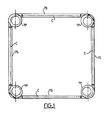
- the structure shown in Figure 1 consists, for example, of four main hollow tubes TP assumed to be vertical, assembled by a plurality of secondary tubes TS horizontal or oblique, in reinforced concrete, by prestressing cables C, as is see better in Figure 2.
- the main tubes consist of sections of high-strength concrete fixed one on top of the other, which include, from place to place, N nodes for the passage or anchoring of the prestressing cables of the secondary tubes. .
- nodes are preferably prefabricated because of their particular internal shape which is easier to make in the factory than on site.
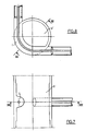
- Figures 3 to 12 show, by way of example, different nodes which are distinguished by their internal shape.
- the knot in FIGS. 3 to 6 is a generally cylindrical tube, the wall of which has, in the central part of the knot, an internal bulge 1 which extends over approximately half the height of the knot and which gradually decreases towards the ends 2, 3 of the node where this wall has a constant thickness such that the hollow of the knot at these ends substantially follows the hollow of the sections (not shown) immediately below and immediately above the main tube which comprises this knot. Because of this swelling, the hollow of the knot at the location of the swelling is a cylinder D whose axis 4 is offset laterally with respect to the axis 5 of the end hollows of the knot.
- the bulged part 1 includes, during manufacture, an internal curved passage 6 for the prestressing cable C of two secondary tubes TS and the node has external (or internal) lateral bosses 7,8 which constitute the lateral tubes bearing surfaces.
- the bulge of a node can have any shape and any size desired depending on the number and the route of the prestressing cables in the bulge.
- Figures 7 and 8 show an embodiment where the bulge is much smaller in height.
- Figures 9 and 10 show an embodiment where the bulge is comparable to that of the knot of Figures 3 to 6, but is performed around the entire periphery of the node while in previous embodiments, this bulge was only carried out on a portion of the perimeter.
- the node When the node must constitute an anchorage for a prestressing cable, it can also have any desired form of bulge but the node locally has at least one lateral surface S where the passage 6 of the prestressing cable opens and which can serve as a support for means for tensioning the cable and retaining the cable ( Figures 11,12). It is not necessary to describe these means which are well known to those skilled in the art.
- the bulge of the wall of the main tube is on the interior side but in alternative embodiments, it is provided, according to the invention, to locate this bulge on the exterior side, if this is preferable or easier .
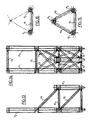
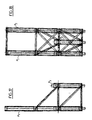
- Figures 13 to 18 relate to an application of the invention to a tripod structure shown by way of example.
- This structure comprises two long tubular posts P1, P2 and a short tubular post P3 assembled by secondary tubes TS prestressed, horizontal and oblique.
Abstract
Description
L'invention concerne une structure tubulaire en béton ainsi que son application comme structure en mer.The invention relates to a tubular concrete structure and its application as a structure at sea.
La structure de l'invention est, au moins pour l'essentiel, constituée de tubes principaux creux assemblés par des tubes secondaires pleins ou creux, l'assemblage étant assuré par des câbles de précontrainte des tubes secondaires qui traversent les tubes principaux en passant dans l'épaisseur de la paroi des tubes principaux sans pénétrer dans les creux des tubes principaux, selon des courbes de passage compatibles avec la fonction de ces câbles.The structure of the invention is, at least essentially, made up of hollow main tubes assembled by solid or hollow secondary tubes, the assembly being provided by prestressing cables of the secondary tubes which pass through the main tubes passing through the thickness of the wall of the main tubes without penetrating into the hollows of the main tubes, according to passage curves compatible with the function of these cables.
Dans des réalisations préférées, la structure de l'invention présente une ou plusieurs des autres caractéristiques suivantes :
- le tube principal présente des bossages pour servir de surfaces d'appui aux extrémités des tubes secondaires ;
- un même câble de précontrainte est utilisé pour assurer l'assemblage d'un ou de deux tubes secondaires à un même tube principal ;
- certains au moins des câbles de précontrainte sont arrêtés sur le tube principal ;
- la paroi du tube principal présente un renflement à l'endroit où doit passer un câble de précontrainte pour augmenter localement l'épaisseur de cette paroi ;
- le creux du tube principal présente un rétrécissement local pour réaliser cette augmentation d'épaisseur ;
- ce rétrécissement local du creux du tube est réalisé sur le pourtour du tube ;
- ce rétrécissement local du creux du tube est réalisé sur une partie seulement du pourtour du tube ;
- les passages des câbles de précontrainte sont réalisés dans des portions de tube principal préfabriquées qui constituent des noeuds tubulaires répartis dans la longueur d'un tube principal.
- the main tube has bosses to serve as bearing surfaces at the ends of the secondary tubes;
- the same prestressing cable is used to assemble one or two secondary tubes to the same main tube;
- at least some of the prestressing cables are stopped on the main tube;
- the wall of the main tube has a bulge at the point where a prestressing cable must pass to locally increase the thickness of this wall;
- the hollow of the main tube has a local narrowing to achieve this increase in thickness;
- this local narrowing of the hollow of the tube is carried out on the periphery of the tube;
- this local narrowing of the hollow of the tube is carried out on only part of the periphery of the tube;
- the passages of the prestressing cables are made in prefabricated main tube portions which constitute tubular nodes distributed in the length of a main tube.
Les câbles de précontrainte sont intérieurs ou extérieurs au béton des tubes secondaires.The prestressing cables are inside or outside the concrete of the secondary tubes.
L'épaississement local de la paroi d'un tube principal pour le passage du câble de précontrainte d'un tube secondaire est particulièrement avantageux du fait que le tube principal offre ainsi une épaisseur de béton à l'arrivée du câble de précontrainte suffisante pour éviter le poinçonnement du tube principal par le tube secondaire précontraint par ce câble.The local thickening of the wall of a main tube for the passage of the prestressing cable from a secondary tube is particularly advantageous since the main tube thus offers a thickness of concrete at the arrival of the prestressing cable sufficient to avoid the punching of the main tube by the secondary tube prestressed by this cable.
En outre, l'invention permet de répartir de la façon la plus uniforme les contraintes de l'assemblage.In addition, the invention makes it possible to distribute the stresses of the assembly in the most uniform manner.
On peut ainsi limiter la quantité de béton à utiliser pour réaliser la structure et utiliser des tubes de section droite inférieure sans compromettre la sécurité de la structure, ce qui est particulièrement avantageux pour une structure en mer.It is thus possible to limit the quantity of concrete to be used to make the structure and to use tubes of lower cross section without compromising the safety of the structure, which is particularly advantageous for a structure at sea.
De façon en soi connue, les passages prévus dans les tubes principaux pour les câbles des précontraintes peuvent comporter des gaines facilitant l'introduction des câbles.In a manner known per se, the passages provided in the main tubes for the prestressing cables can include sheaths facilitating the introduction of the cables.
On décrira ci-après des exemples non limitatifs de mise en oeuvre de l'invention, en référence aux figures du dessin joint, étant précisé que ces figures ont essentiellement pour but de faciliter la compréhension de l'invention par des schémas de principe.Non-limiting examples of implementation of the invention will be described below, with reference to the figures in the accompanying drawing, it being specified that these figures are essentially intended to facilitate understanding of the invention by block diagrams.
La figure 1 est une vue en plan schématique d'une structure élémentaire constituée de quatre tubes principaux assemblés par des tubes secondaires ;
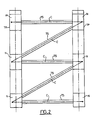
- la figure 2 est une élévation de la structure de la figure 1 ;
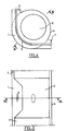
- la figure 3 est une coupe verticale schématique d'un tube principal dans la région d'un noeud tubulaire qui constitue une portion du tube et qui comporte dans sa paroi un passage pour un câble de précontrainte commun à deux tubes secondaires qui sont assemblés au tube principal à l'endroit de ce noeud ;
- la figure 4 est une coupe horizontale du noeud de la figure 3 selon le plan A-A de la figure 3 ;
- les figures 5 et 6 reproduisent respectivement les figures 3 et 4 mais on y a représenté également les extrémités des tubes secondaires ;
- les figures 7 et 8 sont comparables respectivement aux figures 5 et 6 mais dans le cas d'une variante de réalisation du rétrécissement du creux du noeud ;
- les figures 9 et 10 sont comparables respectivement aux figures 5 et 6 mais dans le cas d'une autre variante de réalisation du rétrécissement du creux du noeud ;
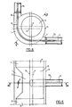
- les figures 11 et 12 sont comparables respectivement aux figures 3 et 4 mais dans le cas où le câble de précontrainte d'un tube secondaire s'arrête sur le noeud ;
- la figure 13 est une vue latérale d'une structure tripode conforme à l'invention ;
- la figure 14 est une élévation de la structure de la figure 13 ;
- les figures 15 et 16 sont des coupes de la structure des figures 13 et 14 par des plans horizontaux, à deux niveaux, et
- les figures 17 et 18, respectivement comparables à la figure 13 et à la figure 14, montrent les armatures et les câbles de précontrainte.
- Figure 2 is an elevation of the structure of Figure 1;
- Figure 3 is a schematic vertical section of a main tube in the region of a tubular node which constitutes a portion of the tube and which has in its wall a passage for a prestressing cable common to two secondary tubes which are assembled to the tube principal at the location of this node;
- Figure 4 is a horizontal section of the node of Figure 3 along the plane AA of Figure 3;
- Figures 5 and 6 reproduce Figures 3 and 4 respectively, but the ends of the secondary tubes are also shown there;
- Figures 7 and 8 are respectively comparable to Figures 5 and 6 but in the case of an alternative embodiment of the narrowing of the hollow of the node;
- Figures 9 and 10 are respectively comparable to Figures 5 and 6 but in the case of another alternative embodiment of the narrowing of the hollow of the node;
- Figures 11 and 12 are respectively comparable to Figures 3 and 4 but in the case where the prestressing cable of a secondary tube stops on the node;
- Figure 13 is a side view of a tripod structure according to the invention;
- Figure 14 is an elevation of the structure of Figure 13;
- FIGS. 15 and 16 are sections of the structure of FIGS. 13 and 14 by horizontal planes, on two levels, and
- Figures 17 and 18, respectively comparable to Figure 13 and Figure 14, show the reinforcements and prestressing cables.
La structure représentée sur la figure 1 est constituée, pour l'exemple, de quatre tubes principaux creux TP supposés verticaux, assemblés par une pluralité de tubes secondaires TS horizontaux ou obliques, en béton armé, par des câbles de précontrainte C, comme on le voit mieux sur la figure 2.The structure shown in Figure 1 consists, for example, of four main hollow tubes TP assumed to be vertical, assembled by a plurality of secondary tubes TS horizontal or oblique, in reinforced concrete, by prestressing cables C, as is see better in Figure 2.
Les tubes principaux sont constitués de tronçons en béton à haute résistance fixés l'un sur l'autre de proche en proche et qui comprennent, de place en place, des noeuds N pour le passage ou l'ancrage des câbles de précontrainte des tubes secondaires.The main tubes consist of sections of high-strength concrete fixed one on top of the other, which include, from place to place, N nodes for the passage or anchoring of the prestressing cables of the secondary tubes. .
Ces noeuds sont de préférence préfabriqués en raison de leur forme interne particulière plus facile à réaliser en usine que sur chantier.These nodes are preferably prefabricated because of their particular internal shape which is easier to make in the factory than on site.
Les figures 3 à 12 montrent, à titre d'exemples, différents noeuds qui se distinguent par leur forme interne.Figures 3 to 12 show, by way of example, different nodes which are distinguished by their internal shape.
Le noeud des figures 3 à 6 est un tube généralement cylindrique dont la paroi présente, dans la partie centrale du noeud, un renflement interne 1 qui s'étend sur la moitié environ de la hauteur du noeud et qui diminue progressivement vers les extrémités 2,3 du noeud où cette paroi a une épaisseur constante telle que le creux du noeud à ces extrémités épouse sensiblement le creux des tronçons (non représentés) immédiatement inférieur et immédiatement supérieur du tube principal qui comporte ce noeud. Du fait de ce renflement, le creux du noeud à l'endroit du renflement est un cylindre D dont l'axe 4 est décalé latéralement par rapport à l'axe 5 des creux d'extrémité du noeud. La partie renflée 1 comporte, de fabrication, un passage courbe interne 6 pour le câble de précontrainte C de deux tubes secondaires TS et le noeud présente aux endroits d'appui des tubes secondaires des bossages latéraux externes (ou internes) 7,8 qui constituent des surfaces d'appui.The knot in FIGS. 3 to 6 is a generally cylindrical tube, the wall of which has, in the central part of the knot, an
Le renflement d'un noeud peut avoir toute forme et toute importance désirée selon le nombre et le parcours des câbles de précontrainte dans le renflement.The bulge of a node can have any shape and any size desired depending on the number and the route of the prestressing cables in the bulge.
Les figures 7 et 8 montrent une réalisation où le renflement l'est beaucoup plus réduit en hauteur.Figures 7 and 8 show an embodiment where the bulge is much smaller in height.
Les figures 9 et 10 montrent une réalisation où le renflement l'est comparable à celui du noeud des figures 3 à 6, mais est réalisé sur tout le pourtour du noeud tandis que dans les réalisations précédentes, ce renflement n'était réalisé que sur une portion du pourtour.Figures 9 and 10 show an embodiment where the bulge is comparable to that of the knot of Figures 3 to 6, but is performed around the entire periphery of the node while in previous embodiments, this bulge was only carried out on a portion of the perimeter.
Ces exemples ne sont pas limitatifs.These examples are not limitative.
Lorsque le noeud doit constituer un ancrage pour un câble de précontrainte, il peut également avoir toute forme de renflement désirée mais le noeud présente localement au moins une surface latérale S où débouche le passage 6 du câble de précontrainte et qui peut servir d'appui à des moyens de mise en tension de câble et de retenue du câble (figures 11,12). Il n'est pas nécessaire de décrire ces moyens qui sont bien connus de l'homme de métier.When the node must constitute an anchorage for a prestressing cable, it can also have any desired form of bulge but the node locally has at least one lateral surface S where the
Dans les réalisations qui sont représentées, le renflement de la paroi du tube principal est du côté intérieur mais dans des variantes de réalisation, il est prévu, selon l'invention, de situer ce renflement du côté extérieur, si cela est préférable ou plus facile.In the embodiments which are shown, the bulge of the wall of the main tube is on the interior side but in alternative embodiments, it is provided, according to the invention, to locate this bulge on the exterior side, if this is preferable or easier .
Les figures 13 à 18 sont relatives à une application de l'invention jà une structure tripode montrée à titre d'exemple. Cette structure comporte deux poteaux tubulaires longs P₁,P₂ et un poteau tubulaire court P₃ assemblés par des tubes secondaires TS précontraints, horizontaux et obliques.Figures 13 to 18 relate to an application of the invention to a tripod structure shown by way of example. This structure comprises two long tubular posts P₁, P₂ and a short tubular post P₃ assembled by secondary tubes TS prestressed, horizontal and oblique.
Claims (10)
Applications Claiming Priority (2)
| Application Number | Priority Date | Filing Date | Title |
|---|---|---|---|
| FR9003107 | 1990-03-12 | ||
| FR9003107A FR2659368B1 (en) | 1990-03-12 | 1990-03-12 | CONCRETE TUBULAR STRUCTURE, ESPECIALLY FOR A STRUCTURE AT SEA. |
Publications (2)
| Publication Number | Publication Date |
|---|---|
| EP0447310A1 true EP0447310A1 (en) | 1991-09-18 |
| EP0447310B1 EP0447310B1 (en) | 1993-09-29 |
Family
ID=9394619
Family Applications (1)
| Application Number | Title | Priority Date | Filing Date |
|---|---|---|---|
| EP91400662A Expired - Lifetime EP0447310B1 (en) | 1990-03-12 | 1991-03-11 | Concrete tubular structure, especially for offshore structures |
Country Status (4)
| Country | Link |
|---|---|
| EP (1) | EP0447310B1 (en) |
| DE (1) | DE69100415D1 (en) |
| FR (1) | FR2659368B1 (en) |
| NO (1) | NO910912L (en) |
Cited By (6)
| Publication number | Priority date | Publication date | Assignee | Title |
|---|---|---|---|---|
| FR2693226A1 (en) * | 1992-07-03 | 1994-01-07 | Prefatlantique | Improved reinforced concrete post with climbing bars - uses thicker wall in hollow post to support bars passed diagonally through corners of post to provide climbing bars |
| WO2010117289A3 (en) * | 2009-04-07 | 2011-11-24 | Carlos Manuel Chastre Rodrigues | Truss tower |
| WO2011147473A1 (en) * | 2010-05-25 | 2011-12-01 | Siemens Aktiengesellschaft | Jacket structure for offshore constructions |
| KR101290328B1 (en) | 2011-06-10 | 2013-07-26 | 건국대학교 산학협력단 | Offshore structure using void member and construction method thereof |
| EP2857614A1 (en) * | 2013-10-03 | 2015-04-08 | Francisco Jose Saenz Saenz | Concrete tower formed with precast pieces |
| US20190063029A1 (en) * | 2016-02-18 | 2019-02-28 | Holcim Technology Ltd | Foundation for a wind mill |
Citations (4)
| Publication number | Priority date | Publication date | Assignee | Title |
|---|---|---|---|---|
| FR2291320A1 (en) * | 1974-11-12 | 1976-06-11 | Kjeld Vik | Stationary supporting structure - has central steel pipe passing through stack of hollow sections filled with concrete |
| FR2299462A1 (en) * | 1975-01-31 | 1976-08-27 | Ono Taisaburo | Underwater scaffolding frame component - has tubular section with elastic end pieces fitting into spherical hollow junction pieces |
| DE3115531A1 (en) * | 1980-04-18 | 1982-02-04 | Hitachi, Ltd., Tokyo | CONNECTION FOR ASSEMBLING A MAIN PIPE AND Auxiliary Pipe Of A Truss Construction |
| EP0146468A2 (en) * | 1983-12-14 | 1985-06-26 | Bouygues | Gravity concrete base for an offshore platform |
-
1990
- 1990-03-12 FR FR9003107A patent/FR2659368B1/en not_active Expired - Fee Related
-
1991
- 1991-03-07 NO NO91910912A patent/NO910912L/en unknown
- 1991-03-11 DE DE91400662T patent/DE69100415D1/en not_active Expired - Lifetime
- 1991-03-11 EP EP91400662A patent/EP0447310B1/en not_active Expired - Lifetime
Patent Citations (4)
| Publication number | Priority date | Publication date | Assignee | Title |
|---|---|---|---|---|
| FR2291320A1 (en) * | 1974-11-12 | 1976-06-11 | Kjeld Vik | Stationary supporting structure - has central steel pipe passing through stack of hollow sections filled with concrete |
| FR2299462A1 (en) * | 1975-01-31 | 1976-08-27 | Ono Taisaburo | Underwater scaffolding frame component - has tubular section with elastic end pieces fitting into spherical hollow junction pieces |
| DE3115531A1 (en) * | 1980-04-18 | 1982-02-04 | Hitachi, Ltd., Tokyo | CONNECTION FOR ASSEMBLING A MAIN PIPE AND Auxiliary Pipe Of A Truss Construction |
| EP0146468A2 (en) * | 1983-12-14 | 1985-06-26 | Bouygues | Gravity concrete base for an offshore platform |
Cited By (10)
| Publication number | Priority date | Publication date | Assignee | Title |
|---|---|---|---|---|
| FR2693226A1 (en) * | 1992-07-03 | 1994-01-07 | Prefatlantique | Improved reinforced concrete post with climbing bars - uses thicker wall in hollow post to support bars passed diagonally through corners of post to provide climbing bars |
| WO2010117289A3 (en) * | 2009-04-07 | 2011-11-24 | Carlos Manuel Chastre Rodrigues | Truss tower |
| WO2011147473A1 (en) * | 2010-05-25 | 2011-12-01 | Siemens Aktiengesellschaft | Jacket structure for offshore constructions |
| CN102906338A (en) * | 2010-05-25 | 2013-01-30 | 西门子公司 | Jacket structure for offshore constructions |
| KR101290328B1 (en) | 2011-06-10 | 2013-07-26 | 건국대학교 산학협력단 | Offshore structure using void member and construction method thereof |
| EP2857614A1 (en) * | 2013-10-03 | 2015-04-08 | Francisco Jose Saenz Saenz | Concrete tower formed with precast pieces |
| WO2015049362A1 (en) * | 2013-10-03 | 2015-04-09 | Sáenz Sáenz Franciso José | Concrete tower formed with precast pieces |
| US20190063029A1 (en) * | 2016-02-18 | 2019-02-28 | Holcim Technology Ltd | Foundation for a wind mill |
| US10968592B2 (en) * | 2016-02-18 | 2021-04-06 | Holcim Technology Ltd | Foundation for a wind mill |
| US11795653B2 (en) | 2016-02-18 | 2023-10-24 | Holcim Technology Ltd | Foundation for a wind mill |
Also Published As
| Publication number | Publication date |
|---|---|
| EP0447310B1 (en) | 1993-09-29 |
| NO910912L (en) | 1991-09-13 |
| DE69100415D1 (en) | 1993-11-04 |
| FR2659368A1 (en) | 1991-09-13 |
| FR2659368B1 (en) | 1992-07-10 |
| NO910912D0 (en) | 1991-03-07 |
Similar Documents
| Publication | Publication Date | Title |
|---|---|---|
| EP2486199B1 (en) | Collapsible lattice beam, truss and construction including such a beam | |
| EP0053965B1 (en) | Prestressed concrete structure, method of constructing the same and elements for carrying out the method | |
| CA1335475C (en) | Anchoring element, especially for concrete | |
| FR2669714A1 (en) | PROFILEE HOLLOW HOLLOW. | |
| EP0447310B1 (en) | Concrete tubular structure, especially for offshore structures | |
| BE1027537B1 (en) | PREFABRICATED MODULE FOR THE CONSTRUCTION OF A WALL OR A WALL DRESSED WITH NATURAL STONES PILED LIKE DRY STONE | |
| EP0465303B1 (en) | Improvements in cable-stayed bridges, especially in their cables and pillars | |
| FR2823784A1 (en) | Erection and lowering system for lattice mast comprises connecting equipment support mast to lifting mast by several cables which pass through tackle system integral with lifting mast | |
| EP0034541B1 (en) | Flue or vertical pipe for gas discharge | |
| EP0126011B1 (en) | Process for obtaining hollow structures such as ducts, silos or shelters | |
| FR2724405A3 (en) | Pile for supporting longitudinally extending loads above ground i.e. transmission lines and like | |
| EP2702208B1 (en) | Sluice gate | |
| EP4124692B1 (en) | Movable wall with concrete framework | |
| EP1371785B1 (en) | Prefabricated element for manhole and manhole | |
| CA3029277A1 (en) | Uhpc post - composite post | |
| EP1479854A1 (en) | Post with semicircular grooves to support welded wired panels and a hand rail and fence with such posts | |
| FR2634856A1 (en) | Concrete pipe | |
| FR2588586A1 (en) | Aluminium structure for a dismantlable truss and its method of erection | |
| FR2811344A1 (en) | Motor road safety barrier has round-section timber rails reinforced by steel strips in slots fastened to supports by bolts and spacers | |
| EP0742327A1 (en) | Dismountable wall | |
| EP1418283A1 (en) | Modular load carrying structure | |
| FR2757889A1 (en) | Prefabricated slabs for floors in high rise buildings | |
| FR2516630A1 (en) | Construction of conduit which lies directly on ground surface - has cross=section of optimum shape determined by calculation and formed by welded sections | |
| FR2653473A1 (en) | Helical stairway and a method for its construction | |
| WO1985005392A1 (en) | Method for erecting building walls and construction elements for implementing such method |
Legal Events
| Date | Code | Title | Description |
|---|---|---|---|
| PUAI | Public reference made under article 153(3) epc to a published international application that has entered the european phase |
Free format text: ORIGINAL CODE: 0009012 |
|
| AK | Designated contracting states |
Kind code of ref document: A1 Designated state(s): BE DE DK ES GB GR IT NL SE |
|
| 17P | Request for examination filed |
Effective date: 19920224 |
|
| 17Q | First examination report despatched |
Effective date: 19920427 |
|
| GRAA | (expected) grant |
Free format text: ORIGINAL CODE: 0009210 |
|
| AK | Designated contracting states |
Kind code of ref document: B1 Designated state(s): BE DE DK ES GB GR IT NL SE |
|
| PG25 | Lapsed in a contracting state [announced via postgrant information from national office to epo] |
Ref country code: IT Free format text: LAPSE BECAUSE OF FAILURE TO SUBMIT A TRANSLATION OF THE DESCRIPTION OR TO PAY THE FEE WITHIN THE PRE;WARNING: LAPSES OF ITALIAN PATENTS WITH EFFECTIVE DATE BEFORE 2007 MAY HAVE OCCURRED AT ANY TIME BEFORE 2007. THE CORRECT EFFECTIVE DATE MAY BE DIFFERENT FROM THE ONE RECORDED.SCRIBED TIME-LIMIT Effective date: 19930929 Ref country code: DK Effective date: 19930929 Ref country code: DE Effective date: 19930929 Ref country code: SE Effective date: 19930929 Ref country code: NL Effective date: 19930929 Ref country code: GR Free format text: LAPSE BECAUSE OF FAILURE TO SUBMIT A TRANSLATION OF THE DESCRIPTION OR TO PAY THE FEE WITHIN THE PRESCRIBED TIME-LIMIT Effective date: 19930929 Ref country code: ES Free format text: THE PATENT HAS BEEN ANNULLED BY A DECISION OF A NATIONAL AUTHORITY Effective date: 19930929 Ref country code: GB Effective date: 19930929 |
|
| REF | Corresponds to: |
Ref document number: 69100415 Country of ref document: DE Date of ref document: 19931104 |
|
| NLV1 | Nl: lapsed or annulled due to failure to fulfill the requirements of art. 29p and 29m of the patents act | ||
| PG25 | Lapsed in a contracting state [announced via postgrant information from national office to epo] |
Ref country code: BE Effective date: 19940331 |
|
| GBV | Gb: ep patent (uk) treated as always having been void in accordance with gb section 77(7)/1977 [no translation filed] |
Effective date: 19930929 |
|
| PLBE | No opposition filed within time limit |
Free format text: ORIGINAL CODE: 0009261 |
|
| STAA | Information on the status of an ep patent application or granted ep patent |
Free format text: STATUS: NO OPPOSITION FILED WITHIN TIME LIMIT |
|
| 26N | No opposition filed | ||
| BERE | Be: lapsed |
Owner name: BOUYGUES OFFSHORE Effective date: 19940331 |