EP0446901B1 - Dispositif pour l'alimentation continue en bandes - Google Patents
Dispositif pour l'alimentation continue en bandes Download PDFInfo
- Publication number
- EP0446901B1 EP0446901B1 EP91103851A EP91103851A EP0446901B1 EP 0446901 B1 EP0446901 B1 EP 0446901B1 EP 91103851 A EP91103851 A EP 91103851A EP 91103851 A EP91103851 A EP 91103851A EP 0446901 B1 EP0446901 B1 EP 0446901B1
- Authority
- EP
- European Patent Office
- Prior art keywords
- film
- type material
- shafts
- links
- new
- Prior art date
- Legal status (The legal status is an assumption and is not a legal conclusion. Google has not performed a legal analysis and makes no representation as to the accuracy of the status listed.)
- Expired - Lifetime
Links
- 239000000463 material Substances 0.000 claims description 39
- 230000007246 mechanism Effects 0.000 claims description 34
- 230000033001 locomotion Effects 0.000 claims description 7
- 230000002441 reversible effect Effects 0.000 claims description 6
- 230000001360 synchronised effect Effects 0.000 claims description 4
- 239000000853 adhesive Substances 0.000 claims description 3
- 230000001070 adhesive effect Effects 0.000 claims description 3
- 230000001133 acceleration Effects 0.000 description 3
- 239000002390 adhesive tape Substances 0.000 description 2
- 230000005540 biological transmission Effects 0.000 description 2
- 238000010276 construction Methods 0.000 description 2
- XEEYBQQBJWHFJM-UHFFFAOYSA-N Iron Chemical group [Fe] XEEYBQQBJWHFJM-UHFFFAOYSA-N 0.000 description 1
- 230000009471 action Effects 0.000 description 1
- 230000008901 benefit Effects 0.000 description 1
- 210000000078 claw Anatomy 0.000 description 1
- 238000001514 detection method Methods 0.000 description 1
- 230000001771 impaired effect Effects 0.000 description 1
- 238000009434 installation Methods 0.000 description 1
- 238000000034 method Methods 0.000 description 1
- 230000004044 response Effects 0.000 description 1
Images
Classifications
-
- B—PERFORMING OPERATIONS; TRANSPORTING
- B65—CONVEYING; PACKING; STORING; HANDLING THIN OR FILAMENTARY MATERIAL
- B65H—HANDLING THIN OR FILAMENTARY MATERIAL, e.g. SHEETS, WEBS, CABLES
- B65H19/00—Changing the web roll
- B65H19/10—Changing the web roll in unwinding mechanisms or in connection with unwinding operations
- B65H19/18—Attaching, e.g. pasting, the replacement web to the expiring web
- B65H19/1857—Support arrangement of web rolls
- B65H19/1868—The roll support being of the turret type
-
- B—PERFORMING OPERATIONS; TRANSPORTING
- B65—CONVEYING; PACKING; STORING; HANDLING THIN OR FILAMENTARY MATERIAL
- B65H—HANDLING THIN OR FILAMENTARY MATERIAL, e.g. SHEETS, WEBS, CABLES
- B65H18/00—Winding webs
-
- B—PERFORMING OPERATIONS; TRANSPORTING
- B65—CONVEYING; PACKING; STORING; HANDLING THIN OR FILAMENTARY MATERIAL
- B65H—HANDLING THIN OR FILAMENTARY MATERIAL, e.g. SHEETS, WEBS, CABLES
- B65H19/00—Changing the web roll
- B65H19/10—Changing the web roll in unwinding mechanisms or in connection with unwinding operations
- B65H19/18—Attaching, e.g. pasting, the replacement web to the expiring web
- B65H19/1805—Flying splicing, i.e. the expiring web moving during splicing contact
- B65H19/1826—Flying splicing, i.e. the expiring web moving during splicing contact taking place at a distance from the replacement roll
- B65H19/1836—Flying splicing, i.e. the expiring web moving during splicing contact taking place at a distance from the replacement roll the replacement web being accelerated or running prior to splicing contact
-
- B—PERFORMING OPERATIONS; TRANSPORTING
- B65—CONVEYING; PACKING; STORING; HANDLING THIN OR FILAMENTARY MATERIAL
- B65H—HANDLING THIN OR FILAMENTARY MATERIAL, e.g. SHEETS, WEBS, CABLES
- B65H19/00—Changing the web roll
- B65H19/10—Changing the web roll in unwinding mechanisms or in connection with unwinding operations
- B65H19/20—Cutting-off the expiring web
-
- B—PERFORMING OPERATIONS; TRANSPORTING
- B65—CONVEYING; PACKING; STORING; HANDLING THIN OR FILAMENTARY MATERIAL
- B65H—HANDLING THIN OR FILAMENTARY MATERIAL, e.g. SHEETS, WEBS, CABLES
- B65H2301/00—Handling processes for sheets or webs
- B65H2301/40—Type of handling process
- B65H2301/46—Splicing
- B65H2301/461—Processing webs in splicing process
- B65H2301/4611—Processing webs in splicing process before splicing
- B65H2301/46115—Processing webs in splicing process before splicing by bringing leading edge to splicing station, e.g. by chain or belt
-
- B—PERFORMING OPERATIONS; TRANSPORTING
- B65—CONVEYING; PACKING; STORING; HANDLING THIN OR FILAMENTARY MATERIAL
- B65H—HANDLING THIN OR FILAMENTARY MATERIAL, e.g. SHEETS, WEBS, CABLES
- B65H2301/00—Handling processes for sheets or webs
- B65H2301/40—Type of handling process
- B65H2301/46—Splicing
- B65H2301/464—Splicing effecting splice
- B65H2301/46412—Splicing effecting splice by element moving in a direction perpendicular to the running direction of the web
Definitions
- the invention relates to an apparatus for continuously supplying a film-type material while connecting a new-film-type material to a preceding film-type material running at a predetermined speed, comprising a synchronizing mechanism for synchronizing the movement of the new film-type material with the running of the preceding film-type material and a connecting mechanism for connecting the leading end of the synchronized new film-type material to the preceding film-type material.
- JP-A-63-106256 discloses an apparatus which is capable of connecting a new film to the trailing end of a preceding film while the films are running at the normal running speed.
- Such an apparatus essentially requires an accumulator which can accumulate or store a predetermined length of the new film which is determined by the time necessary for connecting the new film to the preceding film.
- the accumulator has a multiplicity of stages of rollers around which the film is folded to form a plurality of turns. Therefore, problems are encountered such as damaging of the film or lateral slipping of the film on the roller surfaces, as well as wrinkling of the film.
- the provision of the accumulator occupies a considerable space and requires a specific control device for controlling the accumulator. As a consequence, the cost of the whole apparatus is raised uneconomically.
- the known apparatus does not have any function for attaining synchronization of running speed between the new film and the preceding film which is running at the normal steady speed.
- the known apparatus is not designed to realize a compact construction.
- the time required for a manual work necessarily employed in the connecting operation exceeds a predetermined time which is allowed by the operation of the apparatus, the operation has to be stopped with the result that the quality of the product is impaired.
- the generic prior art according to the EP-A-0 273 286 discloses an apparatus for sticking labels (seals with adhesive) to packages which have the same size and are being conveyed at an equal interval.
- the labels are conveyed as a continuously running web.
- a preceding web is severed to establish a trailing edge thereon and a new web is severed to establish a leading edge thereon.
- the leading edge of the new web is brought to a position on the anvil at which the leading edge of the new web abuts the trailing edge of the preceding web.
- a block holding a splice strip is pressed onto the anvil to splice the trailing edge portion of the preceding web and the leading edge portion of the new web with the splice strip.
- the preceding web moves intermittently by the operation of a feed claw and the pressing action of the block is effected during the time period during which the preceding web is stationary.
- the object of the present invention is to provide an apparatus for continuously supplying a film-type material capable of automatically connecting the film-type material while continuously supplying the material at the steady speed.
- the apparatus of the generic kind comprises according to the invention a holding mechanism including a pair of links secured to respective shafts rotatably supported on a frame extending from a base and a holding means operatively connected to the lower ends of said links through pivots, said links being swingable about the axes of said shafts while keeping a parallelogram defined by said shafts and pivots located at its respective corners, said synchronizing mechanism comprising a driving mechanism for rotating said pair of shafts in normal and reverse directions to cause the swinging motion of said links such that the normal rotation of said shafts causes said holding means to be accelerated to move in synchronization with the movement of said preceding film-type material running at said predetermined speed, and said connecting mechanism comprising a pressing means operatively connected to the lower ends of said links to cooperate with said holding means and a magnetic means for operating said pressing means to press an adhesive material, which is attached to the leading end of said synchronized new film-type material, onto said preceding film-type material.
- the holding means is capable of holding the leading end of the new film-type material to be connected such that the new film-type material is in parallel with the preceding film-type material with the axes of both film-type materials aligned with each other.
- the new film-type material is held stably so as not to be deformed or come off the holding means during acceleration and synchronization.
- the synchronizing means can smoothly accelerating the holding means. Acceleration in the initial period of synchronizing operation is applied not in the feeding direction of the film-type material but in the thicknesswise direction of the same, so that collapsing of the new film-type material is avoided.
- the connecting means is incorporated in the synchronizing means and is adapted to press, when the synchronization is obtained, a manually supplied bonding tape to the portions of the film-type materials to be bonded. As a consequence, connection can be accomplished without any trouble attributable to a difference of speed between two film-type materials.
- the necessity for an accumulator for storing the film in a length corresponding to the time required for the connection is eliminated.
- amount of the film to be wasted is reduced because the connecting operation can be completed without stopping the line.
- the operator is not mentally stressed by a limitation of the time available for the connection.
- the apparatus reduces the installation space because it does not have an accumulator. This advantage becomes more significant in accordance with increase in the film size and the feeding speed.
- the apparatus according to the invention allows a synchronization of running speed between the new film and the preceding film, it is designed to realize a compact construction, and it continuously supplies the material at the steady speed without requiring a complicated accumulator and its associated devices, thereby eliminating necessity for a high degree of skill and experience of the operator and improving the working environment.
- the splicing operation in the apparatus of the present invention is effected while the preceding film-type material is running in a predetermined speed. Accordingly, the new film-type material is accelerated to move in synchronization with the running of the preceding film-type material because of the special structures of the holding mechanism and the synchronizing mechanism.
- the holding means includes a vacuum suction pad or an electromagnet.
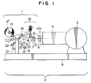
- Fig. 1 shows an apparatus 1 for continuously supplying a film-type material (referred to as a "film” hereinafter) which is a part of a film processing system and is adapted for delivering a film 5 to a processing tank 3 and an introductory section 4.
- a film a film-type material
- a film 5 unwound from a roll 6 is fed at a constant speed in the direction of an arrow in Fig. 1 by a cooperation between a guide roller 7 and drive rollers 8.
- the guide roller 7 and the drive rollers 8 are disposed on the extension of a base 9 of the processing system 2 and are rotatably supported by shafts 10 and 11.
- the drive rollers 8 are power-driven by a suitable drive unit (not shown) at a constant rotation speed.
- the roll 6 is rotatably and replacably carried by an arm 13 through a shaft 12.
- a tension control device (not shown) also is provided to ensure that the film 5 is fed with a constant tension.
- a new roll 15 is rotatably and replacably carried by the end of the arm 13 opposite to the roll 6, through a shaft 14', such that the leading end portion of a new film 16 can be fed into a film connecting mechanism 18 via a guide roller 17 which is rotatably carried by an arm 14 through a shaft 19.
- the arms 13 and 14 are fixed to each other and are rotatably supported on a support 21 fixed to the base 9, through a pivot shaft 20.
- the rotational positions of the arms 13 and 14 are suitably controlled by a driving unit (not shown).
- the new film 16 is connected to the film 5 by the operation of the connecting mechanism 18.
- a guide roller 23 which is rotatably carried by the other end of the arm 14 through a shaft 22 has served to guide the film 5 when the film 5 was connected to a preceding film (not shown).
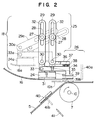
- the connecting device 18 shown in Fig. 2 in detail includes a holding mechanism 24, a synchronizing mechanism 25 and a connecting mechanism 26.
- the holding mechanism 24 is rotatably carried by shafts 30 on links 29 which are rotatably carried by shafts 27 on the extension of the base 9 through a fixing member 28.
- the shafts 27, 30, 30 and 27 form a parallelogram.
- the holding mechanism 24 has a holding portion 31 for stably holding the new film 16.
- the synchronizing mechanism 25 includes a system constituted by the shafts 27, 30, 30 and 27. Before the start of the synchronizing operation, the synchronizing mechanism 25 is stationed at a position shown by broken lines in Fig. 2, i.e., positions indicated at the same reference numerals with suffix "a".
- the shafts 27 are movable within elongated slots 32 so as to vary the radius of rocking of the links 29.
- the connecting mechanism 26 includes a pressing arm 34 pivotally carried by the holding mechanism through a pivot shaft 33, a pressing pad 35 provided on the free end of the arm 34, a support arm 36 on the extension of the holding mechanism 24, an electromagnet 37 with an iron core on the support arm 36, and a permanent magnet 34 on the arm 34.
- the synchronizing mechanism 25 When the synchronizing mechanism 25 is accelerated from the position indicated by broken lines to the position shown by solid lines, the speed of the new film 16 has been elevated to the level at which the film 5 is fed, thus attaining a synchronization between the movement of the new film 16 and the running of the preceding film 5.
- electrical power is supplied to the electromagnet 37 so that a repulsion force is generated between the electromagnet 37 and the permanent magnet 38, with the result that the pressing pad 35 presses an adhesive tape 39, which has been adhered to the leading end of the film 16, downward to a position shown by broken lines, i.e., position denoted by 39b, thus completing the connection of the new film 16b to the film 5.
- the holding mechanism 24 releases the film 16.
- the cutter base 40 is stationed at the position denoted by the broken-lines 40a and is moved to and fixed at the position indicated by 40 immediately before the operation of the connecting device 18.
- a cutter 41 is moved to the broken-line position 41b substantially simultaneously with the pressing operation of the pressing pad 35 so as to severe remaining portion of the film 5.
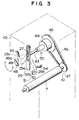
- Each link 29 is rotatably supported on a frame 42 through a shaft 27.
- a support rotary shaft 43 is disengageably connected to a gear 45 through a reversible clutch 44.
- the gear 45 is connected to a pinion 47 through a transmission means such as a chain 46.
- the pinion 47 is fixed to the shaft 10 together with the drive roller 7.
- the link 29 is usually stationed at the broken-line position 29c and is stopped by a stopper 49 which is pivotally supported by the frame 42 through a pivot shaft 48 as the stopper 49 is set to a broken-line position 49a.
- the link 29 is released from the stopper 49a and the reversible clutch 44 is operated in forward direction so that the link is moved to the full-line position 29 past the broken-line position 29a.
- the speed of the link at the full-line position 29 is the same as the speed produced by the drive roller 7.
- the connection of the films is conducted when the link has reached the full-line position 29.
- a phase sensor 50 which produces a signal for disengaging the reversible clutch 44 simultaneously with the start of the connecting operation.
- the link which has been further swung to a chain-line position 29b due to inertia is held by a stopper 52 which is positioned at a broken-line position 52b.
- the stopper 52 is rotatably carried by the frame 42 through a pivot shaft 51. Impacts produced by the link 29 at both rotational stroke ends are absorbed by dampers 53 and 54.
- the link 29 which has been fixed at the chain-line position 29b is then released from the stopper 52b which moves in response to a resetting instruction. Then, the reversible clutch operates in backward direction so as to reset the link 29 to the waiting position 29c.
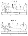
- Figs. 4 and 5 illustrate the method for replacing a roll with a new roll after completion of the connecting operation. More specifically, Fig. 4 shows the state of the apparatus immediately after the completion of the connecting operation. The new roll 15 has been moved to a solid-line position 15b. The new roll 15b further moves to a chain-line position 15c. Fig. 5 shows the roll arrangement in the steady condition. The film is fed from the new roll set at the steady supply position 15c and a next roll 56 is set at a position where it is ready for supplying the film when the roll 15c has become almost empty.
Landscapes
- Replacement Of Web Rolls (AREA)
- Controlling Rewinding, Feeding, Winding, Or Abnormalities Of Webs (AREA)
Claims (3)
- Dispositif pour fournir de manière continue une matière de type pelliculaire tout en raccordant une nouvelle matière (16) de type pelliculaire à une matière précédente (5) de type pelliculaire défilant à une vitesse prédéterminée, comprenant- un mécanisme de synchronisation (25) pour synchroniser le mouvement de la nouvelle matière (16) de type pelliculaire avec le défilement de la matière précédente (5) de type pelliculaire, et- un mécanisme de raccordement (26) pour raccorder à la matière précédente (5) de type pelliculaire l'extrémité antérieure de la nouvelle matière synchronisée (16) de type pelliculaire, caractérisé par- un mécanisme de retenue comprenant une paire de tringles de liaison (29, 29) fixées à des arbres respectifs (27, 27) supportés de façon à pouvoir tourner sur un bâti (42) s'étendant depuis un socle (9) et un moyen de retenue (24) relie fonctionnellement par des pivots (30, 30) aux extrémités inférieures desdites tringles (29,29),- lesdites tringles de liaison (29, 29) pouvant pivoter autour des axes desdits arbres (27, 27) tout en conservant un parallélogramme défini par lesdits arbres (27, 27) et pivots (30, 30) situés à ses angles respectifs,- ledit mécanisme de synchronisation (25) comportant un mécanisme d'entraînement pour faire tourner ladite paire d'arbres (27, 27) dans les sens normal et en marche arrière pour provoquer le mouvement de pivotement desdites tringles (29, 29) de façon que la rotation normale desdits arbres (27, 27) provoque une accélération dudit moyen de retenue (24) pour qu'il se déplace en synchronisme avec le mouvement de ladite matière précédente (5) de type pelliculaire défilant à ladite vitesse prédéterminée, et- ledit mécanisme de raccordement (26) comportant un moyen d'appui (35) relié fonctionnellement aux extrémités inférieures desdites tringles (29, 29) pour coopérer avec ledit moyen de retenue (24) et un moyen magnétique (37, 38) pour actionner ledit moyen d'appui (35) afin d'appliquer sur ladite matière précédente (5) de type pelliculaire une matière adhésive (39) fixée à ladite nouvelle matière synchronisée (16) de type pelliculaire.
- Dispositif selon la revendication 1, dans lequel ledit moyen de retenue (24) comporte une semelle (31) d'aspiration sous vide.
- Dispositif selon la revendication 1, dans lequel ledit moyen de retenue (24) comporte un électro-aimant (31).
Applications Claiming Priority (2)
| Application Number | Priority Date | Filing Date | Title |
|---|---|---|---|
| JP64193/90 | 1990-03-16 | ||
| JP2064193A JPH03267246A (ja) | 1990-03-16 | 1990-03-16 | フイルム状物の連続巻出装置 |
Publications (3)
| Publication Number | Publication Date |
|---|---|
| EP0446901A2 EP0446901A2 (fr) | 1991-09-18 |
| EP0446901A3 EP0446901A3 (en) | 1993-02-24 |
| EP0446901B1 true EP0446901B1 (fr) | 1995-09-27 |
Family
ID=13250987
Family Applications (1)
| Application Number | Title | Priority Date | Filing Date |
|---|---|---|---|
| EP91103851A Expired - Lifetime EP0446901B1 (fr) | 1990-03-16 | 1991-03-13 | Dispositif pour l'alimentation continue en bandes |
Country Status (4)
| Country | Link |
|---|---|
| EP (1) | EP0446901B1 (fr) |
| JP (1) | JPH03267246A (fr) |
| KR (1) | KR910016595A (fr) |
| DE (1) | DE69113301T2 (fr) |
Cited By (1)
| Publication number | Priority date | Publication date | Assignee | Title |
|---|---|---|---|---|
| DE102009041017A1 (de) * | 2009-09-10 | 2011-03-24 | Krones Ag | Verfahren, Vorrichtung und Klebeband zum Spleißen von Etikettenbändern sowie spleißbares Etikettenband |
Families Citing this family (5)
| Publication number | Priority date | Publication date | Assignee | Title |
|---|---|---|---|---|
| EP0662437B1 (fr) * | 1993-12-16 | 1995-07-19 | Fabriques De Tabac Reunies S.A. | Dispositif de raccordement de bandes en un matériau souple |
| US5827166A (en) * | 1993-12-16 | 1998-10-27 | Philip Morris Incorporated | Device for joining strips of a flexible material |
| JP2014027171A (ja) * | 2012-07-27 | 2014-02-06 | Lintec Corp | シート貼付装置およびシート貼付方法 |
| JP2017126785A (ja) * | 2017-04-06 | 2017-07-20 | リンテック株式会社 | シート貼付装置およびシート貼付方法 |
| KR102014430B1 (ko) | 2019-05-15 | 2019-08-26 | 권미화 | 필름 권출장치 |
Family Cites Families (2)
| Publication number | Priority date | Publication date | Assignee | Title |
|---|---|---|---|---|
| US4561924A (en) * | 1982-10-05 | 1985-12-31 | Hope Henry F | Automatic material splicer for photographic materials |
| JPS63165258A (ja) * | 1986-12-25 | 1988-07-08 | Tokyo Jido Kikai Seisakusho:Kk | 帯状材の自動接続装置 |
-
1990
- 1990-03-16 JP JP2064193A patent/JPH03267246A/ja active Pending
-
1991
- 1991-02-28 KR KR1019910003275A patent/KR910016595A/ko not_active Ceased
- 1991-03-13 EP EP91103851A patent/EP0446901B1/fr not_active Expired - Lifetime
- 1991-03-13 DE DE69113301T patent/DE69113301T2/de not_active Expired - Fee Related
Cited By (1)
| Publication number | Priority date | Publication date | Assignee | Title |
|---|---|---|---|---|
| DE102009041017A1 (de) * | 2009-09-10 | 2011-03-24 | Krones Ag | Verfahren, Vorrichtung und Klebeband zum Spleißen von Etikettenbändern sowie spleißbares Etikettenband |
Also Published As
| Publication number | Publication date |
|---|---|
| DE69113301T2 (de) | 1996-03-14 |
| JPH03267246A (ja) | 1991-11-28 |
| EP0446901A2 (fr) | 1991-09-18 |
| DE69113301D1 (de) | 1995-11-02 |
| KR910016595A (ko) | 1991-11-05 |
| EP0446901A3 (en) | 1993-02-24 |
Similar Documents
| Publication | Publication Date | Title |
|---|---|---|
| US4374576A (en) | Semi-automatic roll winding machine | |
| US4564149A (en) | Device for joining together in a registered and/or abutting manner the ends of two paper or cardboard webs which unwind from two different wheels positioned on a reel star unit of two or more positions | |
| EP0286343B1 (fr) | Applicateur de bande | |
| US4564150A (en) | Apparatus for continuously supplying a web of sheet material | |
| EP0325855B1 (fr) | Dispositif d'application d'adhésif avec transport automatique de la bande de support | |
| US6451145B1 (en) | Web splicing system | |
| US4219378A (en) | Web splicing | |
| JPH07144800A (ja) | 材料ウエブ、特に、包装材ウエブを接続する方法と装置 | |
| EP0446901B1 (fr) | Dispositif pour l'alimentation continue en bandes | |
| US4162025A (en) | Apparatus for unreeling valved sacks which are reeled in overlapping formation | |
| JPS6141240B2 (fr) | ||
| JP2793166B2 (ja) | 貯蔵ウエブロールから繰り出されるウエブの部分を処理するための装置 | |
| US3103320A (en) | Automatic splicing rollstand | |
| EP0227951B1 (fr) | Dispositif d'approvisionnement continu en bande à partir de bobines d'alimentation | |
| US4009841A (en) | Manual flying paster | |
| JPH0776065B2 (ja) | ウエブの接合装置及び方法 | |
| EP1384671A1 (fr) | Méthode pour arrêter et démarrer une machine d'emballage lors d'un changement de production | |
| US3904142A (en) | Machines for interconnecting continuous webs | |
| US4673142A (en) | Apparatus for continuously supplying a web of sheet material | |
| US3721396A (en) | Shear cutting batcher apparatus | |
| US7306184B2 (en) | Splicing vehicle | |
| CA1063578A (fr) | Machines a coller les feuilles par aboutement | |
| JPH0549583B2 (fr) | ||
| US3065923A (en) | Flying splice unwind stand | |
| JPH05229701A (ja) | ロールスタンド |
Legal Events
| Date | Code | Title | Description |
|---|---|---|---|
| PUAI | Public reference made under article 153(3) epc to a published international application that has entered the european phase |
Free format text: ORIGINAL CODE: 0009012 |
|
| 17P | Request for examination filed |
Effective date: 19910313 |
|
| AK | Designated contracting states |
Kind code of ref document: A2 Designated state(s): DE FR GB |
|
| PUAL | Search report despatched |
Free format text: ORIGINAL CODE: 0009013 |
|
| AK | Designated contracting states |
Kind code of ref document: A3 Designated state(s): DE FR GB |
|
| 17Q | First examination report despatched |
Effective date: 19940818 |
|
| GRAA | (expected) grant |
Free format text: ORIGINAL CODE: 0009210 |
|
| AK | Designated contracting states |
Kind code of ref document: B1 Designated state(s): DE FR GB |
|
| REF | Corresponds to: |
Ref document number: 69113301 Country of ref document: DE Date of ref document: 19951102 |
|
| ET | Fr: translation filed | ||
| PLBE | No opposition filed within time limit |
Free format text: ORIGINAL CODE: 0009261 |
|
| STAA | Information on the status of an ep patent application or granted ep patent |
Free format text: STATUS: NO OPPOSITION FILED WITHIN TIME LIMIT |
|
| 26N | No opposition filed | ||
| REG | Reference to a national code |
Ref country code: GB Ref legal event code: IF02 |
|
| PGFP | Annual fee paid to national office [announced via postgrant information from national office to epo] |
Ref country code: FR Payment date: 20020118 Year of fee payment: 12 |
|
| PGFP | Annual fee paid to national office [announced via postgrant information from national office to epo] |
Ref country code: GB Payment date: 20020301 Year of fee payment: 12 |
|
| PGFP | Annual fee paid to national office [announced via postgrant information from national office to epo] |
Ref country code: DE Payment date: 20020529 Year of fee payment: 12 |
|
| PG25 | Lapsed in a contracting state [announced via postgrant information from national office to epo] |
Ref country code: GB Free format text: LAPSE BECAUSE OF NON-PAYMENT OF DUE FEES Effective date: 20030313 |
|
| PG25 | Lapsed in a contracting state [announced via postgrant information from national office to epo] |
Ref country code: DE Free format text: LAPSE BECAUSE OF NON-PAYMENT OF DUE FEES Effective date: 20031001 |
|
| GBPC | Gb: european patent ceased through non-payment of renewal fee |
Effective date: 20030313 |
|
| PG25 | Lapsed in a contracting state [announced via postgrant information from national office to epo] |
Ref country code: FR Free format text: LAPSE BECAUSE OF NON-PAYMENT OF DUE FEES Effective date: 20031127 |
|
| REG | Reference to a national code |
Ref country code: FR Ref legal event code: ST |