EP0446864B2 - Dispositif de télécommande avec fonction d'apprentissage - Google Patents
Dispositif de télécommande avec fonction d'apprentissage Download PDFInfo
- Publication number
- EP0446864B2 EP0446864B2 EP91103746A EP91103746A EP0446864B2 EP 0446864 B2 EP0446864 B2 EP 0446864B2 EP 91103746 A EP91103746 A EP 91103746A EP 91103746 A EP91103746 A EP 91103746A EP 0446864 B2 EP0446864 B2 EP 0446864B2
- Authority
- EP
- European Patent Office
- Prior art keywords
- signal
- remote control
- stored
- signals
- operating
- Prior art date
- Legal status (The legal status is an assumption and is not a legal conclusion. Google has not performed a legal analysis and makes no representation as to the accuracy of the status listed.)
- Expired - Lifetime
Links
- 230000006870 function Effects 0.000 title claims description 42
- 230000004044 response Effects 0.000 claims description 31
- 230000004913 activation Effects 0.000 claims 7
- 230000000977 initiatory effect Effects 0.000 description 8
- 101100087530 Caenorhabditis elegans rom-1 gene Proteins 0.000 description 4
- 101100305983 Mus musculus Rom1 gene Proteins 0.000 description 4
- 230000005540 biological transmission Effects 0.000 description 3
- 238000010586 diagram Methods 0.000 description 3
- 238000006243 chemical reaction Methods 0.000 description 2
- 230000015572 biosynthetic process Effects 0.000 description 1
- 238000010276 construction Methods 0.000 description 1
- 230000006872 improvement Effects 0.000 description 1
- 230000004048 modification Effects 0.000 description 1
- 238000012986 modification Methods 0.000 description 1
Images


Classifications
-
- G—PHYSICS
- G08—SIGNALLING
- G08C—TRANSMISSION SYSTEMS FOR MEASURED VALUES, CONTROL OR SIMILAR SIGNALS
- G08C19/00—Electric signal transmission systems
- G08C19/16—Electric signal transmission systems in which transmission is by pulses
- G08C19/28—Electric signal transmission systems in which transmission is by pulses using pulse code
Definitions
- the present invention relates to a remote controller and, more specifically, to a remote controller with learning function which is capable of providing new remote control signals by reading stored control signals through learning.
- a remote commander of a remotely-controlled apparatus in which the data transmitted from another remote commander is stored in the memory of the remote commander that belongs to the main body, and the thus transmitted data is transmitted again.
- the data transmitted from the other remote commander is stored in a RAM as a user remote control data
- the data transmitted to the remote commander that belongs to the main body is stored in a RAM as an original remote control data.
- a remote controller with learning function comprising a first memory means which is read-only in which information for remote control signal is stored preliminary, a rewritable second memory means having a memory part corresponding to the same operating key that is corresponding to the memory part of the first memory means, and a means to transmit a remote control signal constituted of the information that are read out from the first and the second memory means.
- the information of the remote control signal received from the external is stored in the second memory means, and thus stored information is transmitted together with information stored in the corresponding memory part of the first memory means in accordance with instruction through an operating key of a control panel.
- a remote controller with learning function as shown in Fig. 1 has been proposed.
- the known remote controller has been furnished with receiving function, which enables the remote controller to receive remote control signals transmitted by another remote controller, operating keys and corresponding storage regions.
- the remote control signals transmitted by another remote controller are stored in the respective storage regions that correspond to the specific operating keys, and therby any stored remote control signal can be transmitted by the operation of the corresponding operating key.
- the known remote controller with learning function comprises a microcomputer (hereinafter referred to as "CPU") 1 which performs operational steps in accordance with a prepared control program and having a register Ia or the like.
- CPU microcomputer
- ROM read-only memory
- RAM random access memory
- signals transmitting unit 5 for transmitting remote control signals read from the ROM 2 or the RAM 3 by the CPU 1
- mode changeover switch 6 for changing the operating mode of the remote controller between a learning mode and a transmission mode
- an operating unit 7 having a plurality of operating keys.
- a remote control signal received by the receiving unit 4 from another remote controller, after being switched to the learning mode by the operation of the mode changeover switch 6, is stored temporarily in the register 1a.
- the remote control signal temporarily stored in the register 1a is transferred to the RAM 3 and stored in a storage region where corresponds to the operated key.
- the signal stored in the storage region of the RAM 3 can be transmitted by the transmitting unit 5 as a new remote control signal.
- remote controller with learning function it is possible to carry out a remote control operation, simply, by operating the operating key of a single remote controller, while the rest of prior art remote controllers with learning function have utilized a plurality of remote controllers in order to achieve the same result, thus resulting in the improvement of operability of the remote controller.
- the operating keys are indispensable to perform the operation as it requires the operating keys for learning as well as controlling the remote controller. Further, since new remote control signals are stored in respective storage regions that correspond to the operating keys, it is required for the remote controller to furnish a number of operating keys with the same number of remote control signals to learn, this in turn limits a number of control signal to learn reversely to the number of the operating keys of the remote controller.
- the remote controller it has been necessary for the remote controller to provide operating keys as required by a number of remote control signals, thus resulting in the increase of the size of the remote controller and that the increase in number of operating keys for causing complicated operation.
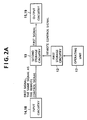
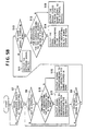
- a remote controller with learning function as shown in Fig. 2A comprising an operating unit 17 having a plurality of operating keys, a first storage circuitry 12 having storage regions which correspond to respective operating keys of the operating unit 17 and storing respective remote control signals beforehand, an input circuitry 14 or 18 for inputting signals from the exterior, a second storage circuitry 13 for storing correspondingly the remote control signal read from the first storage circuitry 12 by operating the operating key of the operating unit 17 and a first signal fed by the input circuitry 14 or 18, and an output circuitry 15 or 19 for outputting the first signal read from the second storage circuitry 13 in response to the operation of the operating key of the operating unit 17, which operating key corresponds to the remote control signal stored in the second storage circuitry 13, or in response to the input of a signal, which is equal to the remote control signal stored in the second storage circuitry 13, to the input circuitry 14 or 18.
- a remote controller with learning function as shown in Fig. 2B comprising an operating unit 17 having a plurality of operating keys, a first storage circuitry 12 having storage regions which correspond to the respective operating keys of the operating unit 17 and storing respective remote control signals beforehand, an input circuitry 14 or 18 for inputting signals from the exterior, a second storage circuitry 13 for storing correspondingly the first and second signals fed by the input circuitry 14 or 18, and an output circuitry 15 or 19 for outputting the second signal read from the second storage circuitry 13 in response to the input of a signal, which is equal to the first signal stored in the second storage circuitry 13, to the input circuitry 14 or 18, or in response to the operation of the operating key of the operating unit 17, which operating key corresponds to the storage region of the first storage circuitry 12 storing the same signal as the first signal being stored in the second storage circuitry 13.
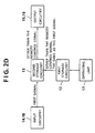
- a remote controller with learning function as shown in Fig. 2C comprising an operating unit 17 having a plurality of operating keys, a first storage circuitry 12 having storage regions which correspond to the respective operating keys of the operating unit 17 and storing respective remote control signals and signals different from these remote control signals in advance, an input circuitry 14 or 18 for inputting a signal from the exterior, a second storage circuitry 13 for storing correspondingly the remote control signal and the signal, which is different from the remote control signal, read from the first storage circuitry 12 by operating the operating key of the operating unit 17 in twice, and an output means 15 or 19 for outputting the signal read from the second storage circuitry 13 in response to the operation of the operating key of the operating unit 17, which operating key corresponds to the remote control signal stored in the second storage circuitry 13, or in response to the input of a signal, which is equal to the remote control signal stored in the second storage circuitry 13, to the input circuitry 14 or 18.
- a remote controller with learning function as shown in Fig. 2D comprising an operating unit 17 having a plurality of operating keys, a first storage circuitry 12 having storage regions which correspond to the respective operating keys of the operating unit 17 and storing remote control signals and signals different from these remote control signals in advance, an input circuitry 14 or 18 for inputting a signal from the exterior, a second storage circuitry 13 for storing correspondingly a first signal fed by the input circuitry 14 or 18 and the signal, which is different from the remote control signal, read from the first storage means by operating the operating key of the operating unit 17, and an output circuitry 15 or 19 for outputting the signal being stored in the second storage circuitry 13 in response to the input of a signal, which is equal to the first signal stored in the second storage circuitry 13, to the input circuitry 14 or 18, or in response to the operation of the operating key corresponding to the storage region of the first storage circuitry 12, which storage region is storing the same signal as the first signal stored in the second
- the learnt new remote control signals can be output only by operating the operating keys capable of specifying any of the signals identical with the signal for reading out or by inputting a signal identical with the signal for reading out from the exterior.
- the learnt new remote control signals can also be read by inputting any of the signals from the exterior for improving the operability of the remote controller with learning function.
- a number of remote control signals to learn can be increased independent of a number of operating keys and remote control signals through different transmission media can also be used for learning as well as for signal conversion.
- a number of remote control signals to learn can also be increased independent of the number of operating keys.
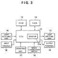
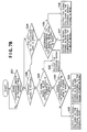
- the remote controller comprises a CPU 11 having a register 11a or the like to perform operations steps in accordance with prepared control programs shown in flowcharts illustrated in the accompanying drawings, which operational steps will be described afterward, a ROM 12 connected to the CPU 11 for storing the control programs, a RAM 13 connected to the CPU 11 for enabling the CPU 11 to write data therein and to read data therefrom, a light receiving unit 14 for receiving an infrared remote control signal from another remote controller (not shown), a light emitting unit 15 for emitting an infrared ray in order to transmit a remote control signal read from the ROM 12 or the RAM 13 through the CPU 11, a mode changeover switch 16 for changing the operating mode of the remote controller between a learning mode and a transmitting mode, an operating unit 17 having a plurality of operating keys, an input terminal 18 for receiving a signal, and an output terminal 19 for providing a remote control signal.
- a CPU 11 having a register 11a or the like to perform operations steps in accordance with prepared control programs shown in flowcharts
- a first embodiment of this invention will be described with reference to the remote controller of Fig. 3.
- An infrared remote control signal D 1 is emitted by an external remote controller towards the light receiving unit 14 after setting the remote controller to a learning mode I by the mode changeover switch 16.
- the infrared remote control signal D 1 received by the light receiving unit 14 is stored temporarily in the register 11a.
- the predetermined key of the operating unit 17 assigned for a predetermined function is operated after setting the remote controller to a learning mode II by the mode changeover switch 16.
- a signal X 1 is stored previously in a predetermined storage area K 1 of the ROM 12, which storage area K 1 corresponds to the aforesaid predetermined operating key.
- the information X 1 for identifying the predetermined key and the signal D 1 temporarily stored in the register 11a are transferred to the RAM 13 and stored correspondingly therein as shown in Fig. 4B.
- the signal D 1 which is stored in the RAM 13 correspondingly with the information X 1 for identifying the predetermined key, is read from the RAM 13 and the light emitting unit 15 emits an infrared remote control signal based on the read signal D 1 .
- the light emitting unit 15 will emit an infrared remote control signal based on the signal X 1 .
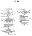
- step S1 determines whether or not the mode changeover switch 15 has switched to the learning mode I. If it has not, the program returns to the start of the program and step S1 is repeated, whereas if it has, it is determined at step S2 whether or not the light receiving unit 14 has received a light remote control signal from an external remote controller. If it has not, namely, if any signal is received by the light receiving unit 14 from the external remote controller, the program repeats step S2, whereas if it has, step S3 stores the signal received from the external remote controller by the light receiving unit 14 temporarily in the register 11a and the program goes to step S4. For example, when the signal D 1 has applied to the remote controller by the external remote controller, the signal D 1 is stored in the register 11a.
- step S4 it is determined whether or not the changeover switch 16 is switched to the learning mode II. If it is not, step S4 is repeated, whereas if it is, it is determined at step S5 whether or not an operating key of the operating unit 17 has operated. If it has not, step S5 is repeated, whereas if it has, the program goes to step S6.
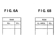
- signals X 1 , 2 , ... are stored in the ROM 12 correspondingly to the respective keys K 1 , 2 , ... of the operating unit 17 as shown in Fig. 4A
- the signal X 1 can be read from the ROM 12 upon operating the key K 1 of the operating unit 17.
- the signal X 1 is read from the ROM 12 upon operating the key K 1 of the operating unit 17 and, at step S6, this read signal X 1 is stored, as a key identifying information, into the RAM 13 together with the signal D 1 provided by the external remote controller and being stored in the register 11a at step S3, as shown in Fig. 4B, and then the program's operation of the CPU 11 will be terminated.
- step S7 determines whether or not the mode changeover switch 16 has switched to the transmitting mode. If it has not, step S7 is repeated, whereas if it has, it is determined at step S8 whether or not the key of the operating unit 17 has operated. If it has not, it is determined at S9 whether or not any external signal is applied to the light receiving unit 14 or to the input terminal 18. If it has not, namely, if any external signal has not applied to the light receiving unit 14 or to the input terminal 18, the program returns to step S8 for repeating the step once again, whereas if it has, it is determined at step S10 whether or not the same signal as the input signal is stored in the ROM 12.
- the light emitting unit 15 emits an infrared remote control signal at step S11 based on the input signal, whereas if it is, namely, when the same signal as the input signal is stored in the ROM 12, it is determined at step S12 whether or not the key identifying information X n corresponding to the signal in the ROM 12 has been stored in the RAM 13. If it has not, the program goes to step S13 and thereby the light emitting unit 15 emits an infrared remote control signal based on the signal stored in the ROM 12. For example, if a signal X 2 is applied to the remote controller from the exterior, the equivalent signal X 2 which is identical to the signal applied from the exterior will be derived therefrom.
- step S14 the program goes to step S14 and thereby the light emitting unit 15 emits an infrared remote control signal based on a signal which corresponds to the key identifying signal stored in the RAM 13. For example, when the external signal X 1 is applied to the remote controller, there is provided a signal D 1 .
- step S15 it is determined at step S15 whether or not any information identifying the operated key is stored in the RAM 13. If it is not, the light emitting unit 15 emits an infrared remote control signal at step S16 based on the signal stored in the ROM 12 which corresponds to the operated key, whereby, when the key K 2 is operated, a signal X 2 is provided for emitting the remote control signal. While if the information identifying the operated key is stored in the RAM 13, the program goes to step 17 and thereby the light emitting unit 15 emits the infrared remote control signal based on a signal stored in the RAM 13 corresponding to the information identifying the operated key. For example, when the K 1 is operated, the signal D 1 is provided for emitting the remote control signal.
- the signal D 1 of the different remote controller is stored in the RAM 13 in correspondence with the signal X 1 which identifies the specific key K 1 , and then the stored signal D 1 is provided not only in response to the operation of the specific key K 1 but to the reception of the external signal X 1 fed from the exterior.
- the remote controller in the first embodiment of this invention has been described with reference to a specific case such that the signal to learn is received through the light receiving unit 14 from the different remote controller, however, a signal received through the input terminal 18 may also be used for learning.
- an output signal to be transmitted may be a remote control signal derived from the output terminal 19 instead of the infrared remote control signal emitted by the light emitting unit 15.
- an infrared remote control signal R1 1 is applied to the light receiving unit 14 by a first external remote controller after switching the mode changeover switch 16 to the learning mode I.
- the infrared remote control signal R1 1 received by the light receiving unit 14 is stored temporarily in a register 11a. Subsequently, another infrared remote control signal R2 1 is applied to the light receiving unit 14 by a second external remote controller after switching the mode changeover switch 16 to the learning mode II.
- the remote control signal R2 1 received from the second external remote controller and the remote control signal R1 1 temporarily stored in the register 11a are fed to the RAM 13 and stored therein in correspondence with each other as shown in Fig. 6A.
- the signal R1 1 which corresponds to the signal R2 1 is read from the RAM 13 and in turn the light emitting unit 15 emits an infrared remote control signal based on the signal R1 1 .
- the signal R1 1 is read from the RAM 13 when the key K n of the operating unit 17 is operated, and then the light emitting unit 15 emits an infrared remote control signal based on the read signal of R1 1 .
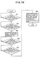
- the CPU 11 determines at step S21 whether or not the mode changeover switch 16 has switched to the learning mode I. If it has not, step S21 is repeated, whereas If it has switched, it is determined at step S22 whether or not the light receiving unit 14 has received a light signal from the first external remote controller. If it has not, step S22 is repeated, whereas if it has, the signal received from the first external remote controller is stored in the register 11a at step S23 and the program goes to step S24. For example, when the signal R1 1 is input from the first external remote controller, the signal R1 1 is stored in the register 11a accordingly.
- step S24 it is determined whether or not the mode changeover switch 16 has switched to the learning mode II. If it has not, step S24 is repeated, whereas if it has, it is determined at step S25 whether or not a signal is received by the light receiving unit 14 from the second external remote controller. If it has not, step S25 is repeated, whereas if it has, namely, when the signal R2 1 is received by the light receiving unit from the second external remote controller, the program goes to step S26 and thereby the signal R2 1 is stored in the RAM 13 in correspondence with the signal R1 1 being stored in the register IIa as shown in Fig. 6A, hence the control program to be performed by the CPU 11 is terminated.
- step S27 it is determined by the CPU 11 at step S27 whether or not the mode changeover switch 16 has switched to the transmitting mode if it has not, step S27 is repeated, whereas if it has, it is further determined at step S28 whether or not any external signal has input to the light receiving unit 14 or to the input terminal 18. If it has, namely, if any external signal is applied to the light receiving unit 14 or to the input terminal 18, the program goes to step S29 and thereby it is determined whether or not the same signal as the received external signal is stored in the ROM 12.
- the light emitting unit 15 emits an infrared remote control signal at step S30 based on the external signal fed from the exterior. While, if the same signal as the signal R2 1 is stored in the ROM 12, the program goes to step S31, and thereby it is determined whether or not the signal in the ROM 12 has stored in the RAM 13. If it has not, the light emitting unit 15 emits an infrared remote control signal at step S32 based on the signal stored in the ROM 12, which is the same signal as the input signal, whereas if it has, the light emitting unit 15 emits an infrared remote control signal at step S33 based on the corresponding signal stored in the RAM 13. For example, when the signal R2 1 is input from the exterior, the signal R1 1 is derived from the RAM 13 for emitting the infrared remote control signal through the light emitting unit 15.
- step S34 If it is determined at step S28 that any external signal has input to the light receiving unit 14 or to the input terminal 18, it is determined at step S34 whether or not the key of the operating unit 17 has turned on. If it has not, the program returns to step S28 for repeating the operational steps, whereas if it has, it is determined at step S35 whether or not an in formation corresponding to the signal read from the ROM 12 is stored in the RAM 13. If it is not, the light emitting unit 15 emits an infrared remote control signal at step S36 based on the stored signal in the ROM 12 corresponding to the operated key, whereas if it is, the light emitting unit 15 emits an infrared remote control signal at step S37 based on the corresponding signal stored in the RAM 13. For example, when the key K n is operated to turn on, the signal R1 1 is derived for exciting the light emitting unit 15.
- the external signal R1 1 input from the first external remote controller and the external signal R2 1 input from the second external remote controller are stored correspondingly in the RAM 13, and the stored signal R1 1 is read therefrom in response to the input of the external signal R2 1 or to the operation of a specific key K n .
- the remote controller in the second embodiment of this invention employs the signal received from the second external remote controller through the light receiving unit 14 for reading out the learnt signal
- the learnt signal may be read out in response to the voice or clamp for transmitting the remote control signal.
- any input signal from the first remote controller through the input terminal 18 may be substituted for the signal through the light receiving unit 14.
- the remote control signal to be transmitted has been the infrared remote control signal emitted by the light emitting unit 15 in the above described second embodiment, however, any remote control signal such as a voice or clap may be transmitted through the output terminal 19.
- the key K 1 of the operating unit 17 is operated after switching the mode changeover switch 16 to the learning mode I to read a signal form the ROM 12 and store it temporarily in the register 11a.
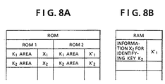
- the signal read from the ROM 12 by operating the key K 1 after the mode changeover switch 16 has switched to the learning mode I is different from a signal provided by the remote controller in response to the operation of the key under the normal usage in carrying out its primary function. For example, as shown in Fig.
- a signal X 1 is read from a ROM 1 in response to the operation of the key K 1 when the remote controller is in a mode for carrying out its primary function, while a signal X 1 ' is read from a ROM 2 in response to the operation of the same key K 1 when the mode changeover switch 16 is switched to the learning mode I.
- the key K 2 (or the key K 1 ) of the operating unit 17 is turned on after the mode changeover switch 16 is switched to the learning mode II.
- the key K 2 also has predetermined function and, in the teaming mode II, a signal X 2 stored in a predetermined storage area of the ROM 12 will be read upon operating the key K 2 . If the signal X 2 is read, the read signal X 2 and the signal X 1 ' being stored temporarily in the register 11a are transferred to the RAM 13 and stored correspondingly therein as shown in Fig. 8B.
- the signal X 1 ' is read from the RAM 13 and in turn the light emitting unit 15 emits an infrared remote control signal based on the signal X 1 ' being read.
- the signal X 1 ' is read from the RAM 13 and then the light emitting unit 15 emits an infrared remote control signal based on the read signal X 1 '.
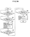
- step S41 Upon initiation of the remote controller, it is determined at step S41 whether or not the mode changeover switch 16 has switched to the learning mode I. If it has not, step S41 is repeated, whereas if it has, it is determined at step S42 whether or not the key of the operating unit 17 has operated. If it has not, step S42 is repeated, whereas if it has, the program goes to step S43 and thereby a signal stored in a predetermined storage area ROM 2 of the ROM 12, which corresponds to the operated key, is read therefrom and is stored temporarily in the register 11a. For example, when the signal X 1 ' is read from the ROM 2 at step S43 in response to the operation of the key K 1 , the signal X 1 ' will be stored in the register 11a.
- step S44 it is determined at step S44, whether or not the mode changeover switch 16 has switched to the learning mode II. If it has not, step S44 is repeated, whereas if it has, it is determined at step S45 whether or not the key of the operating unit 17 has turned on. If it has not, step S45 is repeated, whereas if it has, the program goes to step S46. If the key K 2 has operated at step S45 and the signal X 2 is read from a predetermined area ROM 1 of the ROM 12 in response to the operated key K 2 , the program goes to step S46 and thereby the signal X 2 and the signal X 1 ' being stored temporarily in the register 11a are transferred to the RAM 13 and stored therein in correspondence with each other as shown in Fig. 8B, and then the operational steps of the CPU 11 is terminated.
- step S47 determines whether or not the mode changeover switch 16 has switched to the transmitting mode. If it has not, step 47 is repeated, whereas if it has, it is determined at step S48 whether or not an operating key of the operating unit 17 is operated. If it is, the program goes to step S49 and thereby it is determined whether or not a signal for identifying the operated key is stored in the RAM 13.
- step S50 outputs a signal corresponding to the operated key being stored in the RON 12 and the light emitting unit emits an infrared remote control signal based on the output of the ROM 12, whereas if it is, step S51 outputs the signal corresponding to the operated key being stored in the RAM 13 and the light emitting unit 15 emits an infrared remote control signal based on the output of the RAM 13.
- step S48 If it is determined at step S48 that any operating key of the operating unit 15 is not operated, it is determined at step S52 whether or not any external signal has been applied to the light receiving unit 14 or the input terminal 18. If it has not, the program returns to step S48, whereas if it has, it is determined at step S53 whether or not the same signal as the applied external signal is stored in the ROM 12. If it is not, step S54 outputs the applied external signal directly and the light emitting unit 15 emits an infrared remote control signal based on the applied external signal, whereas if it is, namely, the same signal as the applied external signal is stored in the ROM 12, it is determined at step S55 whether or not a key identifying signal corresponding to the signal stored in the ROM 12 has stored in the RAM 13.
- step S56 outputs the signal stored in the ROM 12, whereas if it has, the step S57 outputs a signal which corresponds to the key identifying signal from the RAM 13 and the light emitting unit 15 emits an infrared remote control signal based on the output of the RAM 13.
- the signal X 1 ' which is generated upon operation of the key of the operating unit 17 under a mode of the remote controller for carrying out a function other than its primary function
- the signal X 2 which is generated upon operation of the key of the operating unit 17 under a mode of the remote controller for carrying out its primary function
- the signal X 1 ' is stored in correspondence with each other in the RAM 13, and thereby the signal X 1 ' is output either in response to the signal X 2 fed from the exterior or in response to the operation of the key K 2 for generating the signal X 2 .
- a fourth embodiment of the present invention will be described hereinafter.
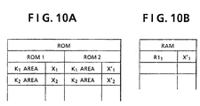
- the key K 1 of the operating unit 17 is operated for reading a signal from ROM 12 and in turn the read signal is stored temporarily in the register 11a.
- the signal read from the ROM 12 by operating the key in the learning mode I is different from a signal read by operating the key while the remote controller is in the mode for carrying out its primary function.
- the signal X 1 is read from the ROM 1 when the key K 1 is operated in the mode for carrying out its primary function
- the signal X 1 ' is read from the ROM 2 when the same key K 1 is operated in the learning mode I.
- an infrared remote control signal R1 1 is applied to the light receiving unit 14 of the remote controller from an external remote controller after setting the remote controller to the learning mode II by operating the mode changeover switch 16.
- the received signal R1 1 and the signal X 1 ' stored temporarily in the register 11a are fed to the RAM 13 and stored therein in correspondence with each other as shown in Fig. 10B.
- the light emitting unit 15 emits an infrared remote control signal based on the read out signal X 1 '.
- the signal X 1 ' may be read from the RAM 13 in response to the operation of the key which corresponds to the signal R1 1 , and in tum the light emitting unit 15 emits an infrared remote control signal based on the read out signal.
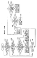
- step S61 determines at step S61 whether or not the mode changeover switch 16 has switched to the learning mode I. If it has not, step S61 is repeated, whereas if it has, it is determined at step S62 whether or not the key of the operating unit 17 has operated. If it has not, step S62 is repeated, whereas if it has, the program goes to step S63 and thereby a signal stored in the predetermined area ROM 2 of the ROM 12 corresponding to the operated key is read out and stored temporarily in the register 11a, and then the program goes to step S64. For example, when the signal X 1 ' is read from the ROM 2 in response to the operation of the key K 1 , the signal X 1 ' is stored temporarily in the register 11a.
- step S64 it is determined whether or not the remote controller has switched to the learning mode II by the operation of the mode changeover switch 16. If it has not, step S64 is repeated, whereas if it has, it is determined as step S65 whether or not the remote controller has received a signal at the light receiving unit 14 from another external remote controller. If it has not, step 65 is repeated, whereas if it has, the program goes to step S66. That is, if the signal R1 1 is input from the external remote controller, the signal R1 1 and the signal X 1 ' being stored in the register 11a are fed to the RAM 13 and stored therein in correspondence with each other at step S66 as shown in Fig. 10B, and then the program of the CPU 11 goes to end.
- Step S67 upon initiation of the remote controller, it is determined at step S67 whether or not the mode changeover switched 16 has switched to the transmitting mode. If it has not, Step S67 is repeated, whereas if it has, it is determined at step S68 whether or not the key of the operating unit 17 has operated. If it has, namely, when the key of the operating unit 17 has operated, it is determined at step S69 whether or not the same signal as the one stored in the ROM 12 corresponding to the operated key is stored in the RAM 13. If it is not, the program goes to step S70. Step S70 outputs the signal corresponding to the operated key from the ROM 12 and the light emitting unit 15 emits an infrared remote control signal based on the signal stored in the ROM 12.
- step S68 namely, when any key of the operating unit 17 is not operated, it is determined at step S72 whether or not any external signal has applied to the light receiving unit 14 or the input terminal 18. If it has not, the program returns to step S68, whereas if it has, it is determined at step S73 whether or not the same signal as the applied external signal is stored in the RAM 13. If it is not, it is determined at step S74 whether or not the same signal as the external signal has stored in the ROM 12. If it has not, step S75 outputs the applied external signal directly, whereas if it has, step S76 outputs the signal stored in the ROM 12. For example, if the signal X 1 is applied to the remote controller, since X 1 ⁇ R1 1 , the signal X 1 will be output.
- step S77 outputs the signal stored in the RAM 13 which corresponds to the external signal.
- the signal X 1 ' is derived from the RAM 13.
- the signal X 1 ' which is generated when the remote controller is in a mode other than the mode for carrying out its primary function upon operating the key of the operating unit 17, and the external signal R1 1 fed from the exterior are stored correspondingly, and this stored signal X 1 ' is output by operating the key which is for generating the same signal as the signal R1 1 or by receiving the external signal R1 1 from the exterior.
- the fourth embodiment has described in such that the signal for reading out the learnt remote control signal has been the signal received from the external remote controller at the light receiving unit 14, however, a signal applied to the input terminal 18 may also be used for the same purpose.
- a learnt remote control signal is stored correspondingly not with an operating key but with a signal for reading the learnt remote control signal. Therefore, it is possible to output the learnt new remote control signal by operating an operating key assigned to the signal which is for reading out the remote control signal or by inputting the same external signal as the signal which is for reading out the remote control signal, and hence the remote controller with learning function embodying the present invention does not require specific keys for reading the learnt remote control signals. Furthermore, the learnt new remote control signals can also be read by entering external signals and the operability of the remote controller with learning function is greatly improved.
- the learnt new remote control signal by inputting the signal which is for reading out the remote control signal from the exterior or by operating an operating key assigned to the same signal as the signal which is for reading out the remote control signal, thus resulting in the same advantages as described above. Furthermore, if new remote control signals to learn and signals for reading out the learnt new remote control signals are both input signals from the exterior, a number of remote control signals to learn can be increased independent of the number of operating keys, and signals through different transmission media can also be learnt as well as converted in accordance with this invention.
Landscapes
- Physics & Mathematics (AREA)
- General Physics & Mathematics (AREA)
- Selective Calling Equipment (AREA)
Claims (4)
- Dispositif de commande à distance pourvu d'une fonction d'apprentissage comprenant :une unité d'activation (17) comportant une pluralité de touches d'activation (K) ;au moins un moyen d'entrée (14, 18) pour entrer des signaux externes qui sont reçus par le dispositif de commande à distance ;des premiers moyens de mémorisation (12) pour mémoriser une pluralité de signaux de commande à distance (X) correspondant respectivement à certaines de ladite pluralité de touches d'activation (K) ;des deuxièmes moyens de mémorisation (13) pour mémoriser des premiers signaux (D) devant être délivrés en tant que signaux de commande à distance appris parmi les signaux externes entrés par l'intermédiaire des moyens d'entrée (14, 18) et des deuxièmes signaux (X) devant être utilisés pour lire lesdits premiers signaux (D), en association les uns avec les autres ; etau moins un moyen d'émission de lumière (15) pour délivrer, en tant que signal de lumière, le premier signal mémorisé (D) lu dans lesdits deuxièmes moyens de mémorisation (13) lorsque l'un des signaux de commande à distance mémorisés (X) lu dans lesdits premiers moyens de mémorisation (12) en réponse à l'activation d'une touche d'activation (K) correspondante ou en réponse à une entrée d'un signal externe vers les moyens d'entrée (14, 18) est sensiblement identique à l'un des deuxièmes signaux mémorisés (X).
- Dispositif de commande à distance pourvu d'une fonction d'apprentissage selon la revendication 1, dans lequel
lesdits premiers moyens de mémorisation (12) comportent des régions de mémorisation correspondant à des touches d'activation (K) respectives de l'unité d'activation (17) et mémorisent une pluralité de signaux de commande à distance (X) correspondant respectivement à certaines de ladite pluralité de touches d'activation (K) dans des régions de mémorisation respectives,
lesdits deuxièmes moyens de mémorisation (13) mémorisent des signaux externes reçus par l'intermédiaire des moyens d'entrée (14, 18) en tant que premiers signaux (D) devant être utilisés comme signaux de commande à distance et des signaux de commande à distance respectifs devant être délivrés en réponse à l'activation de certaines desdites touches d'activation (K) correspondantes en tant que deuxièmes signaux (X) devant être utilisés pour lire les premiers signaux respectifs (D), en association les uns avec les autres, et
lesdits au moins un moyens d'émission de lumière (15, 19) délivrent un premier signal mémorisé (D) lu dans lesdits deuxièmes moyens de mémorisation (13) en tant que signal de lumière de commande à distance appris, après que lesdits premiers et deuxièmes signaux ont été mémorisés dans ceux-ci, lorsqu'un signal lu dans lesdits premiers moyens de mémorisation (12) en réponse à l'activation d'une touche d'activation (K) correspondante ou un signal délivré en réponse à une entrée d'un signal externe vers lesdits moyens d'entrée (14, 18) est sensiblement identique au deuxième signal mémorisé respectif (X). - Dispositif de commande à distance pourvu d'une fonction d'apprentissage selon la revendication 1, dans lequel lesdits premiers moyens de mémorisation (12) comportent des régions de mémorisation qui mémorisent lesdits signaux de commande à distance (X) et des deuxièmes régions de mémorisation qui mémorisent d'autres signaux de commande à distance (X'),
lesdits autres signaux de commande à distance (X') lus dans les deuxièmes régions de mémorisation desdits premiers moyens de mémorisation (12) en réponse à l'activation de certaines de ladite pluralité de touches d'activation (K) de ladite unité d'activation (17) et lesdits signaux de commande à distance (X) lus dans lesdites régions de mémorisation desdits premiers moyens de mémorisation (12) sont respectivement mémorisés dans lesdits deuxièmes moyens de mémorisation (13) en tant que premiers signaux devant être délivrés comme signaux de commande à distance et deuxièmes signaux pour extraire lesdits premiers signaux, en association les uns avec les autres, et
lesdits au moins un moyens d'émission de lumière (15, 19) délivrent le premier signal lu dans les deuxièmes moyens de mémorisation (13), en tant que signal de lumière, généré en réponse à l'activation d'une touche d'activation (K) correspondante de l'unité d'activation (17) ou un signal délivré en réponse à l'entrée du signal externe vers lesdits moyens d'entrée (14, 18) est sensiblement identique audit deuxième signal, après que lesdits premiers signaux et deuxièmes signaux ont été mémorisés dans lesdits deuxièmes moyens de mémorisation (13). - Dispositif de commande à distance pourvu d'une fonction d'apprentissage selon la revendication 1, dans lequel
lesdits premiers moyens de mémorisation (12) comportent des régions de mémorisation correspondant à des touches d'activation (K) respectives de l'unité d'activation (17), qui mémorisent des signaux de commande à distance (X) et d'autres signaux de commande à distance (X') dans des régions de mémorisation,
lesdits deuxièmes moyens de mémorisation (13) mémorisent des signaux externes appliqués extérieurement au dispositif de commande à distance par l'intermédiaire des moyens d'entrée (14, 18) et les autres signaux de commande à distance (X') lus dans lesdits premiers moyens de mémorisation (12) en réponse à l'activation de certaines des touches d'activation (K) respectives de l'unité d'activation (17), en association les uns avec les autres, et
lesdits au moins un moyens d'émission de lumière (15, 19) délivrent un autre signal de commande à distance mémorisé (X') lu dans les deuxièmes moyens de mémorisation (13), en tant que signal de lumière, en réponse au signal externe d'identification entré vers les moyens d'entrée (14, 18) mémorisé dans les deuxièmes moyens de mémorisation (13), et délivrent ledit autre signal de commande à distance mémorisé (X'), en tant que signal de lumière, en réponse à l'activation d'une touche d'activation (K) correspondant à la région de mémorisation desdits premiers moyens de mémorisation (12) qui mémorisent un signal de commande à distance qui est sensiblement identique audit signal externe mémorisé associé audit autre signal de commande à distance mémorisé correspondant à ladite touche d'activation ainsi activée.
Applications Claiming Priority (3)
| Application Number | Priority Date | Filing Date | Title |
|---|---|---|---|
| JP6204690 | 1990-03-13 | ||
| JP2062046A JPH03262398A (ja) | 1990-03-13 | 1990-03-13 | 学習機能付リモートコントロール装置 |
| JP62046/90 | 1990-03-13 |
Publications (4)
| Publication Number | Publication Date |
|---|---|
| EP0446864A2 EP0446864A2 (fr) | 1991-09-18 |
| EP0446864A3 EP0446864A3 (en) | 1992-04-08 |
| EP0446864B1 EP0446864B1 (fr) | 1996-12-18 |
| EP0446864B2 true EP0446864B2 (fr) | 2002-08-28 |
Family
ID=13188830
Family Applications (1)
| Application Number | Title | Priority Date | Filing Date |
|---|---|---|---|
| EP91103746A Expired - Lifetime EP0446864B2 (fr) | 1990-03-13 | 1991-03-12 | Dispositif de télécommande avec fonction d'apprentissage |
Country Status (4)
| Country | Link |
|---|---|
| US (1) | US5229763A (fr) |
| EP (1) | EP0446864B2 (fr) |
| JP (1) | JPH03262398A (fr) |
| DE (1) | DE69123617T3 (fr) |
Families Citing this family (23)
| Publication number | Priority date | Publication date | Assignee | Title |
|---|---|---|---|---|
| US4959810A (en) * | 1987-10-14 | 1990-09-25 | Universal Electronics, Inc. | Universal remote control device |
| US5414426A (en) * | 1987-10-14 | 1995-05-09 | Universal Electronics Inc. | Favorite key macro command and chained macro command in a remote control |
| MY131285A (en) * | 1991-12-13 | 2007-07-31 | Thomson Consumer Electronics | Vcr control of a cable converter unit |
| US5691710A (en) * | 1992-11-02 | 1997-11-25 | Zenith Electronics Corporation | Self learning IR remote control transmitter |
| DE4242231C3 (de) * | 1992-12-15 | 1997-01-16 | Diehl Gmbh & Co | Fernsteuereinrichtung |
| US5629868A (en) * | 1994-02-07 | 1997-05-13 | Le Groupe Videotron Ltee | Method of programming local control |
| US5621484A (en) * | 1994-05-18 | 1997-04-15 | U.S. Philips Corporation | User-programmable control device for a television apparatus |
| US5969774A (en) * | 1994-11-17 | 1999-10-19 | Wininger; Dixon | Programmable remote control transmitter |
| US6756895B2 (en) * | 2002-02-11 | 2004-06-29 | The Chamberlain Group, Inc. | Device learning mode method |
| US6998997B2 (en) * | 2002-05-30 | 2006-02-14 | X10 Wireless Technology, Inc. | System and method for learning macro routines in a remote control |
| US7227444B2 (en) * | 2003-02-13 | 2007-06-05 | The Chamberlain Group, Inc. | Method and apparatus for remote control |
| US20050014563A1 (en) * | 2003-03-12 | 2005-01-20 | Darin Barri | Interactive DVD gaming system |
| DE10352866A1 (de) * | 2003-11-10 | 2005-06-16 | Zahn, Frank, Dipl.-Ing. | Kommunikationsadapter, Verwendung des Kommunikationsadapters sowie Verfahren zur Konvertierung von Signalen |
| US7463164B2 (en) * | 2004-02-13 | 2008-12-09 | Williams Don P | Method and apparatus for remote control of electronic equipment |
| US20060111183A1 (en) * | 2004-11-03 | 2006-05-25 | Peter Maclver | Remote control |
| US8382567B2 (en) * | 2004-11-03 | 2013-02-26 | Mattel, Inc. | Interactive DVD gaming systems |
| US8277297B2 (en) * | 2004-11-03 | 2012-10-02 | Mattel, Inc. | Gaming system |
| US20060111166A1 (en) * | 2004-11-03 | 2006-05-25 | Peter Maclver | Gaming system |
| US7331857B2 (en) * | 2004-11-03 | 2008-02-19 | Mattel, Inc. | Gaming system |
| US20060175753A1 (en) * | 2004-11-23 | 2006-08-10 | Maciver Peter | Electronic game board |
| US20070178966A1 (en) * | 2005-11-03 | 2007-08-02 | Kip Pohlman | Video game controller with expansion panel |
| US20070213111A1 (en) * | 2005-11-04 | 2007-09-13 | Peter Maclver | DVD games |
| WO2018173295A1 (fr) * | 2017-03-24 | 2018-09-27 | ヤマハ株式会社 | Dispositif d'interface d'utilisateur, procédé d'interface d'utilisateur, et système d'utilisation sonore |
Citations (3)
| Publication number | Priority date | Publication date | Assignee | Title |
|---|---|---|---|---|
| GB2197104A (en) † | 1986-10-24 | 1988-05-11 | Sony Corp | Remotely-controllable electronic apparatus including video systems |
| EP0289625A1 (fr) † | 1986-11-12 | 1988-11-09 | Sony Corporation | Telecommande |
| WO1990001847A1 (fr) † | 1988-08-10 | 1990-02-22 | Deutsche Thomson-Brandt Gmbh | Poste recepteur de television |
Family Cites Families (1)
| Publication number | Priority date | Publication date | Assignee | Title |
|---|---|---|---|---|
| DE3469662D1 (en) * | 1983-03-23 | 1988-04-07 | Telefunken Fernseh & Rundfunk | Remote control apparatus controlling various functions of one or more devices |
-
1990
- 1990-03-13 JP JP2062046A patent/JPH03262398A/ja active Pending
-
1991
- 1991-03-08 US US07/666,773 patent/US5229763A/en not_active Expired - Lifetime
- 1991-03-12 EP EP91103746A patent/EP0446864B2/fr not_active Expired - Lifetime
- 1991-03-12 DE DE69123617T patent/DE69123617T3/de not_active Expired - Fee Related
Patent Citations (3)
| Publication number | Priority date | Publication date | Assignee | Title |
|---|---|---|---|---|
| GB2197104A (en) † | 1986-10-24 | 1988-05-11 | Sony Corp | Remotely-controllable electronic apparatus including video systems |
| EP0289625A1 (fr) † | 1986-11-12 | 1988-11-09 | Sony Corporation | Telecommande |
| WO1990001847A1 (fr) † | 1988-08-10 | 1990-02-22 | Deutsche Thomson-Brandt Gmbh | Poste recepteur de television |
Also Published As
| Publication number | Publication date |
|---|---|
| DE69123617D1 (de) | 1997-01-30 |
| EP0446864A2 (fr) | 1991-09-18 |
| EP0446864A3 (en) | 1992-04-08 |
| EP0446864B1 (fr) | 1996-12-18 |
| DE69123617T3 (de) | 2002-12-05 |
| JPH03262398A (ja) | 1991-11-22 |
| DE69123617T2 (de) | 1997-04-17 |
| US5229763A (en) | 1993-07-20 |
Similar Documents
| Publication | Publication Date | Title |
|---|---|---|
| EP0446864B2 (fr) | Dispositif de télécommande avec fonction d'apprentissage | |
| US4495654A (en) | Remote controlled receiver with provisions for automatically programming a channel skip list | |
| US5905245A (en) | IC card reading/writing apparatus and an IC card system | |
| JPH0710091B2 (ja) | 電子機器 | |
| JPH055440B2 (fr) | ||
| US5854594A (en) | Remote controller for controlling a plurality of electric appliances | |
| WO1997039574A1 (fr) | Commutateur de matrices | |
| EP0446856A2 (fr) | Appareil électronique avec signal de sortie sonore | |
| US5086298A (en) | Remote control signal processing device | |
| US5680115A (en) | Remote controlling method | |
| WO1997032290A1 (fr) | Telecommande universelle programmable | |
| JPH0787411A (ja) | Tvとvcrのチャンネル自動切換装置及びチャンネル自動切換方法 | |
| US20030117294A1 (en) | Remote control transmitter and transmit/receive system using the same | |
| JPH11345024A (ja) | リモコン装置 | |
| JP2687392B2 (ja) | リモートコントロール装置 | |
| KR0135855B1 (ko) | 다기능 간편리모콘장치 및 방법 | |
| JPH0417982Y2 (fr) | ||
| JPH0583646A (ja) | Avセレクタ | |
| JP3263911B2 (ja) | リモコン装置 | |
| JP2730213B2 (ja) | リモコンの送信機 | |
| JPS59119995A (ja) | リモ−トコントロ−ル用送信回路 | |
| JPH0246153Y2 (fr) | ||
| JPS5951666A (ja) | 制御装置 | |
| JPS62130099A (ja) | リモ−トコントロ−ル装置 | |
| JPH0294799A (ja) | 学習機能付リモートコントロールユニット |
Legal Events
| Date | Code | Title | Description |
|---|---|---|---|
| PUAI | Public reference made under article 153(3) epc to a published international application that has entered the european phase |
Free format text: ORIGINAL CODE: 0009012 |
|
| AK | Designated contracting states |
Kind code of ref document: A2 Designated state(s): DE FR GB |
|
| PUAL | Search report despatched |
Free format text: ORIGINAL CODE: 0009013 |
|
| AK | Designated contracting states |
Kind code of ref document: A3 Designated state(s): DE FR GB |
|
| 17P | Request for examination filed |
Effective date: 19920916 |
|
| 17Q | First examination report despatched |
Effective date: 19950222 |
|
| GRAG | Despatch of communication of intention to grant |
Free format text: ORIGINAL CODE: EPIDOS AGRA |
|
| GRAH | Despatch of communication of intention to grant a patent |
Free format text: ORIGINAL CODE: EPIDOS IGRA |
|
| GRAH | Despatch of communication of intention to grant a patent |
Free format text: ORIGINAL CODE: EPIDOS IGRA |
|
| GRAA | (expected) grant |
Free format text: ORIGINAL CODE: 0009210 |
|
| AK | Designated contracting states |
Kind code of ref document: B1 Designated state(s): DE FR GB |
|
| REF | Corresponds to: |
Ref document number: 69123617 Country of ref document: DE Date of ref document: 19970130 |
|
| ET | Fr: translation filed | ||
| PLBQ | Unpublished change to opponent data |
Free format text: ORIGINAL CODE: EPIDOS OPPO |
|
| PLBI | Opposition filed |
Free format text: ORIGINAL CODE: 0009260 |
|
| PLBF | Reply of patent proprietor to notice(s) of opposition |
Free format text: ORIGINAL CODE: EPIDOS OBSO |
|
| 26 | Opposition filed |
Opponent name: INTERESSENGEMEINSCHAFT FUER RUNDFUNKSCHUTZRECHTE G Effective date: 19970917 |
|
| REG | Reference to a national code |
Ref country code: GB Ref legal event code: 746 Effective date: 19980210 |
|
| PLBF | Reply of patent proprietor to notice(s) of opposition |
Free format text: ORIGINAL CODE: EPIDOS OBSO |
|
| REG | Reference to a national code |
Ref country code: FR Ref legal event code: D6 |
|
| PLAW | Interlocutory decision in opposition |
Free format text: ORIGINAL CODE: EPIDOS IDOP |
|
| REG | Reference to a national code |
Ref country code: GB Ref legal event code: IF02 |
|
| PLAW | Interlocutory decision in opposition |
Free format text: ORIGINAL CODE: EPIDOS IDOP |
|
| PUAH | Patent maintained in amended form |
Free format text: ORIGINAL CODE: 0009272 |
|
| STAA | Information on the status of an ep patent application or granted ep patent |
Free format text: STATUS: PATENT MAINTAINED AS AMENDED |
|
| 27A | Patent maintained in amended form |
Effective date: 20020828 |
|
| AK | Designated contracting states |
Kind code of ref document: B2 Designated state(s): DE FR GB |
|
| ET3 | Fr: translation filed ** decision concerning opposition | ||
| PGFP | Annual fee paid to national office [announced via postgrant information from national office to epo] |
Ref country code: GB Payment date: 20040310 Year of fee payment: 14 |
|
| PGFP | Annual fee paid to national office [announced via postgrant information from national office to epo] |
Ref country code: DE Payment date: 20040325 Year of fee payment: 14 |
|
| PGFP | Annual fee paid to national office [announced via postgrant information from national office to epo] |
Ref country code: FR Payment date: 20050308 Year of fee payment: 15 |
|
| PG25 | Lapsed in a contracting state [announced via postgrant information from national office to epo] |
Ref country code: GB Free format text: LAPSE BECAUSE OF NON-PAYMENT OF DUE FEES Effective date: 20050312 |
|
| PG25 | Lapsed in a contracting state [announced via postgrant information from national office to epo] |
Ref country code: DE Free format text: LAPSE BECAUSE OF NON-PAYMENT OF DUE FEES Effective date: 20051001 |
|
| GBPC | Gb: european patent ceased through non-payment of renewal fee |
Effective date: 20050312 |
|
| REG | Reference to a national code |
Ref country code: FR Ref legal event code: ST Effective date: 20061130 |
|
| PG25 | Lapsed in a contracting state [announced via postgrant information from national office to epo] |
Ref country code: FR Free format text: LAPSE BECAUSE OF NON-PAYMENT OF DUE FEES Effective date: 20060331 |