EP0446841A1 - Manchon m˩tallique pour ponter une fuite dans un tuyau - Google Patents
Manchon m˩tallique pour ponter une fuite dans un tuyau Download PDFInfo
- Publication number
- EP0446841A1 EP0446841A1 EP91103698A EP91103698A EP0446841A1 EP 0446841 A1 EP0446841 A1 EP 0446841A1 EP 91103698 A EP91103698 A EP 91103698A EP 91103698 A EP91103698 A EP 91103698A EP 0446841 A1 EP0446841 A1 EP 0446841A1
- Authority
- EP
- European Patent Office
- Prior art keywords
- sleeve
- tube
- component
- spiral
- metallic sleeve
- Prior art date
- Legal status (The legal status is an assumption and is not a legal conclusion. Google has not performed a legal analysis and makes no representation as to the accuracy of the status listed.)
- Granted
Links
Images

Classifications
-
- F—MECHANICAL ENGINEERING; LIGHTING; HEATING; WEAPONS; BLASTING
- F28—HEAT EXCHANGE IN GENERAL
- F28F—DETAILS OF HEAT-EXCHANGE AND HEAT-TRANSFER APPARATUS, OF GENERAL APPLICATION
- F28F11/00—Arrangements for sealing leaky tubes and conduits
- F28F11/02—Arrangements for sealing leaky tubes and conduits using obturating elements, e.g. washers, inserted and operated independently of each other
-
- B—PERFORMING OPERATIONS; TRANSPORTING
- B21—MECHANICAL METAL-WORKING WITHOUT ESSENTIALLY REMOVING MATERIAL; PUNCHING METAL
- B21D—WORKING OR PROCESSING OF SHEET METAL OR METAL TUBES, RODS OR PROFILES WITHOUT ESSENTIALLY REMOVING MATERIAL; PUNCHING METAL
- B21D39/00—Application of procedures in order to connect objects or parts, e.g. coating with sheet metal otherwise than by plating; Tube expanders
- B21D39/08—Tube expanders
- B21D39/18—Rollers of special shape
-
- F—MECHANICAL ENGINEERING; LIGHTING; HEATING; WEAPONS; BLASTING
- F16—ENGINEERING ELEMENTS AND UNITS; GENERAL MEASURES FOR PRODUCING AND MAINTAINING EFFECTIVE FUNCTIONING OF MACHINES OR INSTALLATIONS; THERMAL INSULATION IN GENERAL
- F16L—PIPES; JOINTS OR FITTINGS FOR PIPES; SUPPORTS FOR PIPES, CABLES OR PROTECTIVE TUBING; MEANS FOR THERMAL INSULATION IN GENERAL
- F16L55/00—Devices or appurtenances for use in, or in connection with, pipes or pipe systems
- F16L55/16—Devices for covering leaks in pipes or hoses, e.g. hose-menders
- F16L55/162—Devices for covering leaks in pipes or hoses, e.g. hose-menders from inside the pipe
- F16L55/163—Devices for covering leaks in pipes or hoses, e.g. hose-menders from inside the pipe a ring, a band or a sleeve being pressed against the inner surface of the pipe
-
- C—CHEMISTRY; METALLURGY
- C08—ORGANIC MACROMOLECULAR COMPOUNDS; THEIR PREPARATION OR CHEMICAL WORKING-UP; COMPOSITIONS BASED THEREON
- C08L—COMPOSITIONS OF MACROMOLECULAR COMPOUNDS
- C08L2201/00—Properties
- C08L2201/12—Shape memory
-
- F—MECHANICAL ENGINEERING; LIGHTING; HEATING; WEAPONS; BLASTING
- F28—HEAT EXCHANGE IN GENERAL
- F28F—DETAILS OF HEAT-EXCHANGE AND HEAT-TRANSFER APPARATUS, OF GENERAL APPLICATION
- F28F2255/00—Heat exchanger elements made of materials having special features or resulting from particular manufacturing processes
- F28F2255/04—Heat exchanger elements made of materials having special features or resulting from particular manufacturing processes comprising shape memory alloys or bimetallic elements
-
- Y—GENERAL TAGGING OF NEW TECHNOLOGICAL DEVELOPMENTS; GENERAL TAGGING OF CROSS-SECTIONAL TECHNOLOGIES SPANNING OVER SEVERAL SECTIONS OF THE IPC; TECHNICAL SUBJECTS COVERED BY FORMER USPC CROSS-REFERENCE ART COLLECTIONS [XRACs] AND DIGESTS
- Y02—TECHNOLOGIES OR APPLICATIONS FOR MITIGATION OR ADAPTATION AGAINST CLIMATE CHANGE
- Y02P—CLIMATE CHANGE MITIGATION TECHNOLOGIES IN THE PRODUCTION OR PROCESSING OF GOODS
- Y02P20/00—Technologies relating to chemical industry
- Y02P20/141—Feedstock
Definitions
- the invention relates to a metallic sleeve for bridging a leakage point of a pipe, which can be applied to the inner wall surface of the pipe using the expansion technique.
- Such a sleeve is known from EP-A-00 47 407.
- the sleeve has a toothed portion near its upper and lower ends. After the teeth have penetrated into the tube wall in a first step by hydraulic widening of these areas, the area lying between the teeth is also hydraulically expanded in a second step. The shrinking process occurring in the axial direction is intended to support the connection between the tube and the sleeve in the region of the toothing.
- the weld is a heat treatment that can lead to undesirable stresses and also increases the time required for pipe repair. There are also no signs of corrosion in the gap.
- the sleeve carries a plurality of components made of a shape memory alloy on the circumference, which, when a predeterminable temperature is reached, form a seal between the sleeve and the tube.
- the component made of a shape memory alloy also carries out the expansion movement of the sleeve, so that after the expansion process has ended and the springback has taken place, a gap is present between the sleeve or the component made of the shape memory alloy and the tube.
- the shape memory alloy set to this operating temperature is expanded due to the shape memory effect in order to produce a seal between the sleeve and the tube.
- a further embodiment provides that in each case a component is arranged at the end regions of the sleeve and, when a predeterminable temperature is reached, a seal between the sleeve and the tube represents that the sleeve has an expansion area at its end facing away from the component, which part with a lower surface hardness and a part with a greater surface hardness than that of the pipe and the part with the greater surface hardness is provided with a profile.
- This solution is used when the sleeve has to be inserted at one end into a tube part extending outside a tube sheet and at the other end into a tube part extending into a tube sheet of a heat exchanger.
- the differences in springback in the area of the tube sheet are negligible, so that the use of a component made of a shape memory alloy is not necessary there.
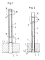
- FIG. 1 shows the partial area of a tube sheet 1 of a heat exchanger, which is not shown in further detail.
- a multiplicity of tubes 2 ends in the tube sheet, only one of which is shown.
- the tube 2 is connected to a cladding 4 of the tube sheet 1 via a weld seam 3.
- a sleeve 6 is introduced into the tube 2 and connected at its end regions 7, 8 by widening to an area of the tube 2 located above the tube plate 1.
- the sleeve 6 is expanded hydraulically in an area outside the tube sheet 1, for example, a different springback of the tube 2 and the sleeve 6 occurs, which is in a gap of expresses about 5 to 10 microns, which occurs at the widened end regions 7, 8 between the tube 2 and the sleeve 6 after the expansion process has ended.
- the sleeve 6 is widened with its one end area 7 in the area of the tube sheet 1 and with its other end area 8 in the area outside the tube sheet.
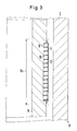
- FIG. 3 shown on a larger scale, shows the design of the end regions 7 and 8 according to FIG. 1 and of the end region 8 according to FIG. 2 (detail "X") of the sleeve 6 before it expands.
- the expansion area 8a (7a in FIG. 1) has an approximately 0.2 mm deep free rotation 9, into which a component made of a shape memory alloy formed as a sheet metal strip 10 is inserted in a spiral.
- An approximately 0.2 mm thick layer 11 covers the spiral component.
- the gap between tube 2 and the layer outside is approximately 0.3 mm before expansion. After the expansion process, which is not shown in FIG. 3, the springback described above takes place, which leads to a gap width of approximately 5 to 10 ⁇ m between the tube 2 and the sleeve 6.
- the property of the shape memory alloy is selected so that when the operating temperature of the heat exchanger has been reached it has expanded in such a way that a gap-bridging and sealing connection with the tube 2 is formed with the interposition of the layer 11.
- the layer 11 in addition to its corrosion-protecting cover, closes a space 12 between the spindle windings to prevent leakage.
- a leak medium could enter space 12 at one end and then along the spiral Windings that delimit space 12 penetrate the expansion area in the axial direction of the sleeve. If the corrosion-protecting coating can be dispensed with, the introduction of the layer 11 into the space 12 is sufficient to avoid leakage.
- the layer 11 thus does not overlap the metal strip 10.
- the expansion area 8a assigned to the end area 8 has at least one closed ring 13 made of a shape memory alloy.
- the leakage passage described with regard to the spiral configuration according to FIG. 3 cannot take place here.
- a layer 11 would therefore at best be required for corrosion protection purposes.
- the rings 13 can be formed both wire-shaped and as a sheet metal strip. It is only important that the change in thickness induced by the shape memory effect is dimensioned sufficiently large to reliably bridge the gap formed due to the springback when the predetermined temperature is reached.
- FIGS. 3 and 4 can be used for the details “X” according to FIGS. 1 and 2 (widening outside the tube sheet 1).
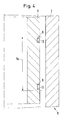
- the sleeve 6 extends with one end into the tube sheet 1, then it is designed in its expansion area 7a in accordance with FIG. 5.
- a half-section shows the sleeve 6 with its expansion area 7a on a larger scale before the expansion process.
- the sleeve 6 is provided with a collar 14 which represents the part with the lower surface hardness than that of the tube 2.
- a layer 15 is applied below the collar 14. She assigns one Profiling on and represents the part with the greater surface hardness than that of the pipe.
- the collar 14 and the layer 15 are drawn oversized.
- the collar 14 projects approximately 0.05-0.1 mm beyond the remaining outer surface of the sleeve 6 and has a width of approximately 10 mm.
- the preferably sprayed-on layer 15, like the collar 14, also projects 0.05 to 0.1 mm beyond the remaining lateral surface of the sleeve 6 and has a width of approximately 7 mm.
- the profile depth of the profiling of layer 15 is approximately 0.01 to 0.05 mm.
- the change in yield strength in the material of the hollow cylindrical part caused by compression simultaneously causes an increase in the non-positive connection between the sleeve 6 and the tube 2.
- the profiling of the layer 15, which has a greater hardness than the inner wall 2 penetrates so far (namely 0.01 to 0.05 mm) into the inner wall of the tube, as dictated by the deformation process of the collar 14 and thus brings about a positive connection between the sleeve and the tube.
- Relatively small expansion forces per unit area enable the connection to the pipe 2 to be achieved, since the large profile area means that a maximum penetration depth of 0.05 mm is sufficient for a reliable connection.
- the low expansion forces therefore also exclude pipe damage if the sleeve 6 is expanded above the tube sheet 1.
- the fine-pored structure of the profiling 16 is interrupted by ring-shaped components 13 made of a shape memory alloy, which are embedded in the outer surface of the sleeve 6 at predetermined intervals.
- the area provided with a profiling 16 has the same outer diameter as the components 13.
- the thickness of the components 13 is shown larger for better illustration. It is usually about 0.2 mm, so that these components can be designed as a sheet metal strip. After expansion of the sleeve and after reaching a predetermined temperature, the components 13 will bridge the gap caused by the springback and seal absolutely against leakage.
Landscapes
- Engineering & Computer Science (AREA)
- Mechanical Engineering (AREA)
- General Engineering & Computer Science (AREA)
- Physics & Mathematics (AREA)
- Thermal Sciences (AREA)
- Non-Disconnectible Joints And Screw-Threaded Joints (AREA)
- Pipe Accessories (AREA)
- Heat-Exchange Devices With Radiators And Conduit Assemblies (AREA)
Applications Claiming Priority (4)
| Application Number | Priority Date | Filing Date | Title |
|---|---|---|---|
| DE4008252 | 1990-03-15 | ||
| DE19904008252 DE4008252A1 (de) | 1990-03-15 | 1990-03-15 | Metallische huelse zur ueberbrueckung einer leckagestelle eines rohres |
| DE19904011136 DE4011136C1 (en) | 1990-04-06 | 1990-04-06 | Sleeve for sealing leaking pipe - has rings of shape retaining alloy spaced along periphery of sleeve |
| DE4011136 | 1990-04-06 |
Publications (2)
| Publication Number | Publication Date |
|---|---|
| EP0446841A1 true EP0446841A1 (fr) | 1991-09-18 |
| EP0446841B1 EP0446841B1 (fr) | 1994-10-12 |
Family
ID=25891151
Family Applications (1)
| Application Number | Title | Priority Date | Filing Date |
|---|---|---|---|
| EP91103698A Expired - Lifetime EP0446841B1 (fr) | 1990-03-15 | 1991-03-11 | Manchon métallique pour ponter une fuite dans un tuyau |
Country Status (5)
| Country | Link |
|---|---|
| EP (1) | EP0446841B1 (fr) |
| JP (1) | JPH04219590A (fr) |
| KR (1) | KR910016401A (fr) |
| DE (1) | DE59103194D1 (fr) |
| ES (1) | ES2064787T3 (fr) |
Cited By (7)
| Publication number | Priority date | Publication date | Assignee | Title |
|---|---|---|---|---|
| DE4243213C1 (de) * | 1992-12-19 | 1994-01-20 | Bbc Reaktor Gmbh | Verfahren zur Festlegung einer Hülse in einem Rohr unter Verwendung von mehreren Ringen aus einer Formgedächtnislegierung und Einrichtung zur Herstellung eines Ringes |
| DE4311674C1 (de) * | 1993-04-08 | 1994-04-21 | Bbc Reaktor Gmbh | Abdichtung zwischen einem eine Leckagestelle aufweisenden Rohr und einer Hülse und Verfahren zum Herstellen einer Abdichtung |
| EP0607052A2 (fr) * | 1993-01-15 | 1994-07-20 | Babcock Construction Limited | Procédé et appareil pour la réparation d'un tuyau métallique |
| DE4433501A1 (de) * | 1994-09-20 | 1996-03-21 | Siemens Ag | Reparaturhülse und Verfahren zur Reparatur eines Wärmetauscherrohres |
| FR2726885A1 (fr) * | 1994-11-15 | 1996-05-15 | Framatome Sa | Procede de fixation resistante et etanche d'une manchette a l'interieur d'un tube metallique et manchette de reparation d'un tube metallique |
| WO1997021956A2 (fr) * | 1995-12-15 | 1997-06-19 | Westinghouse Electric Corporation | Systeme et procede de stabilisation d'un tube de transfert thermique d'echangeur nucleaire |
| WO1999047843A2 (fr) | 1998-03-17 | 1999-09-23 | Siemens Aktiengesellschaft | Tube presentant une zone d'elargissement et procede de production d'un tel tube |
Citations (5)
| Publication number | Priority date | Publication date | Assignee | Title |
|---|---|---|---|---|
| EP0137984A2 (fr) * | 1983-10-14 | 1985-04-24 | Lummus Crest S.A.R.L. | Manchon de réparation pour tube de générateur de vapeur |
| EP0248728A1 (fr) * | 1986-06-04 | 1987-12-09 | Framatome | Procédé de fixation résistante et étanche d'un élément cylindrique creux à l'intérieur d'un tube et élément cylindrique pour la mise en oeuvre de ce procédé |
| US4723578A (en) * | 1985-06-24 | 1988-02-09 | Combustion Engineering, Inc. | Steam generator tube repair method and assembly |
| FR2608727A1 (fr) * | 1986-12-23 | 1988-06-24 | Souriau & Cie | Dispositif d'obturation d'un corps creux comprenant un element en materiau a memoire de forme |
| EP0291003A1 (fr) * | 1987-05-15 | 1988-11-17 | ABB Reaktor GmbH | Bouchon creux pour rendre étanche un tube d'échangeur de chaleur |
Family Cites Families (1)
| Publication number | Priority date | Publication date | Assignee | Title |
|---|---|---|---|---|
| US4368571A (en) * | 1980-09-09 | 1983-01-18 | Westinghouse Electric Corp. | Sleeving method |
-
1991
- 1991-03-11 ES ES91103698T patent/ES2064787T3/es not_active Expired - Lifetime
- 1991-03-11 EP EP91103698A patent/EP0446841B1/fr not_active Expired - Lifetime
- 1991-03-11 DE DE59103194T patent/DE59103194D1/de not_active Expired - Fee Related
- 1991-03-12 KR KR1019910003939A patent/KR910016401A/ko not_active Application Discontinuation
- 1991-03-15 JP JP3075659A patent/JPH04219590A/ja active Pending
Patent Citations (5)
| Publication number | Priority date | Publication date | Assignee | Title |
|---|---|---|---|---|
| EP0137984A2 (fr) * | 1983-10-14 | 1985-04-24 | Lummus Crest S.A.R.L. | Manchon de réparation pour tube de générateur de vapeur |
| US4723578A (en) * | 1985-06-24 | 1988-02-09 | Combustion Engineering, Inc. | Steam generator tube repair method and assembly |
| EP0248728A1 (fr) * | 1986-06-04 | 1987-12-09 | Framatome | Procédé de fixation résistante et étanche d'un élément cylindrique creux à l'intérieur d'un tube et élément cylindrique pour la mise en oeuvre de ce procédé |
| FR2608727A1 (fr) * | 1986-12-23 | 1988-06-24 | Souriau & Cie | Dispositif d'obturation d'un corps creux comprenant un element en materiau a memoire de forme |
| EP0291003A1 (fr) * | 1987-05-15 | 1988-11-17 | ABB Reaktor GmbH | Bouchon creux pour rendre étanche un tube d'échangeur de chaleur |
Non-Patent Citations (3)
| Title |
|---|
| PATENT ABSTRACTS OF JAPAN vol. 11, no. 1 (M-550)(2448) 07 Februar 1987, & JP-A-61 180895 (HITACHI) 13 August 1986, * |
| PATENT ABSTRACTS OF JAPAN vol. 12, no. 428 (M-762)(3275) 11 November 1988, & JP-A-63 161395 (SUMITOMO METAL) 05 Juli 1988, * |
| PATENT ABSTRACTS OF JAPAN vol. 9, no. 29 (M-356)(1752) 07 Februar 1985, & JP-A-59 173696 (HITACHI SEISAKUSHO) 01 Oktober 1984, * |
Cited By (12)
| Publication number | Priority date | Publication date | Assignee | Title |
|---|---|---|---|---|
| DE4243213C1 (de) * | 1992-12-19 | 1994-01-20 | Bbc Reaktor Gmbh | Verfahren zur Festlegung einer Hülse in einem Rohr unter Verwendung von mehreren Ringen aus einer Formgedächtnislegierung und Einrichtung zur Herstellung eines Ringes |
| EP0607052A2 (fr) * | 1993-01-15 | 1994-07-20 | Babcock Construction Limited | Procédé et appareil pour la réparation d'un tuyau métallique |
| EP0607052A3 (fr) * | 1993-01-15 | 1994-08-03 | Babcock Constr Ltd | |
| DE4311674C1 (de) * | 1993-04-08 | 1994-04-21 | Bbc Reaktor Gmbh | Abdichtung zwischen einem eine Leckagestelle aufweisenden Rohr und einer Hülse und Verfahren zum Herstellen einer Abdichtung |
| DE4433501A1 (de) * | 1994-09-20 | 1996-03-21 | Siemens Ag | Reparaturhülse und Verfahren zur Reparatur eines Wärmetauscherrohres |
| FR2726885A1 (fr) * | 1994-11-15 | 1996-05-15 | Framatome Sa | Procede de fixation resistante et etanche d'une manchette a l'interieur d'un tube metallique et manchette de reparation d'un tube metallique |
| EP0713049A1 (fr) * | 1994-11-15 | 1996-05-22 | Framatome | Procédé de fixation résistante et étanche d'une manchette à l'intérieur d'un tube métallique et manchette de réparation d'un tube métallique |
| WO1997021956A2 (fr) * | 1995-12-15 | 1997-06-19 | Westinghouse Electric Corporation | Systeme et procede de stabilisation d'un tube de transfert thermique d'echangeur nucleaire |
| WO1997021956A3 (fr) * | 1995-12-15 | 1997-08-28 | Westinghouse Electric Corp | Systeme et procede de stabilisation d'un tube de transfert thermique d'echangeur nucleaire |
| WO1999047843A2 (fr) | 1998-03-17 | 1999-09-23 | Siemens Aktiengesellschaft | Tube presentant une zone d'elargissement et procede de production d'un tel tube |
| DE19811599A1 (de) * | 1998-03-17 | 1999-09-30 | Siemens Ag | Rohr mit einem Aufweitbereich |
| DE19811599C2 (de) * | 1998-03-17 | 2002-01-10 | Framatome Anp Gmbh | Rohr mit einem Aufweitbereich |
Also Published As
| Publication number | Publication date |
|---|---|
| ES2064787T3 (es) | 1995-02-01 |
| KR910016401A (ko) | 1991-11-05 |
| JPH04219590A (ja) | 1992-08-10 |
| DE59103194D1 (de) | 1994-11-17 |
| EP0446841B1 (fr) | 1994-10-12 |
Similar Documents
| Publication | Publication Date | Title |
|---|---|---|
| EP0462530B1 (fr) | Méthode pour étancher un tuyau avec un manchon | |
| DE4406167C2 (de) | Verfahren zum Erzielen einer dichten Verbindung zwischen einem Rohr und einer Hülse | |
| DE3135966C2 (de) | Verfahren zur Herstellung mehrschichtiger Schraubennahtrohre | |
| DE3716328C2 (fr) | ||
| EP0446841A1 (fr) | Manchon m˩tallique pour ponter une fuite dans un tuyau | |
| DE1514958A1 (de) | Kernreaktor-Brennstoffelement und Verfahren und Vorrichtung zum Verschliessen eines Schutzrohrs fuer dieses | |
| DE4008252C2 (fr) | ||
| DE3130272A1 (de) | Vorrichtung zur festlegung einer rohrleitung | |
| CH657908A5 (de) | Kompensator fuer rohrleitungen. | |
| DE3830439A1 (de) | Verfahren zum herstellen eines leckanzeige- und/oder waermedaemmspaltes zwischen einer wand und verkleidungsplatten sowie hierfuer verwendbare verkleidungsplatten | |
| DE4011136C1 (en) | Sleeve for sealing leaking pipe - has rings of shape retaining alloy spaced along periphery of sleeve | |
| DE2362926A1 (de) | Verfahren zum verbinden von rohren sowie rohrmuffe zur durchfuehrung des verfahrens | |
| EP0332954A1 (fr) | Elément de liaison métallique inoxydable | |
| EP0447391B1 (fr) | Element d'obturation pour tubes d'echange de chaleur defectueuse | |
| DE2033213A1 (en) | Heat exchanger tube seal - for electrical machine coolers comprising sealing ring in tube plate | |
| DE19513604A1 (de) | Verfahren zum Verbinden zweier Rohre unterschiedlicher Materialien | |
| EP0687849A1 (fr) | Procédé pour empêcher la propagation rapide des fissures dans les tubes en matière plastique et tubes obtenus selon ce procédé | |
| DE3107310A1 (de) | Rohrfoermige ueberschubmuffe fuer den verbindungsbereich von rohrschuessen eines waermegedaemmten rohres | |
| DE3534241A1 (de) | Verfahren zur herstellung einer daemmung aus polyurethan-ortschaum fuer rohrleitungen, behaelter und kolonnen | |
| EP0350802A1 (fr) | Méthode pour rénovation de pipe-lines | |
| DE10207199A1 (de) | Verfahren zum Verschließen eines Lecks in einer Rohrleitung aus Metall | |
| DE2528739C2 (de) | Verfahren zur druckdichten Befestigung von Rohren an einer Rohrscheibe | |
| EP0916889B1 (fr) | Méthode de renforcement d'un tuyau et un tuyau renforcé | |
| DE2924376A1 (de) | Verfahren und einrichtung zum einwalzen eines rohres in einen rohrboden | |
| DE1451286C (de) | Verfahren zur Herstellung eines Wärmetauschers |
Legal Events
| Date | Code | Title | Description |
|---|---|---|---|
| PUAI | Public reference made under article 153(3) epc to a published international application that has entered the european phase |
Free format text: ORIGINAL CODE: 0009012 |
|
| AK | Designated contracting states |
Kind code of ref document: A1 Designated state(s): BE CH DE ES FR GB LI NL SE |
|
| 17P | Request for examination filed |
Effective date: 19911008 |
|
| 17Q | First examination report despatched |
Effective date: 19921105 |
|
| GRAA | (expected) grant |
Free format text: ORIGINAL CODE: 0009210 |
|
| AK | Designated contracting states |
Kind code of ref document: B1 Designated state(s): BE CH DE ES FR GB LI NL SE |
|
| ET | Fr: translation filed | ||
| REF | Corresponds to: |
Ref document number: 59103194 Country of ref document: DE Date of ref document: 19941117 |
|
| GBT | Gb: translation of ep patent filed (gb section 77(6)(a)/1977) |
Effective date: 19941103 |
|
| EAL | Se: european patent in force in sweden |
Ref document number: 91103698.6 |
|
| REG | Reference to a national code |
Ref country code: ES Ref legal event code: FG2A Ref document number: 2064787 Country of ref document: ES Kind code of ref document: T3 |
|
| PGFP | Annual fee paid to national office [announced via postgrant information from national office to epo] |
Ref country code: NL Payment date: 19950331 Year of fee payment: 5 |
|
| PLBE | No opposition filed within time limit |
Free format text: ORIGINAL CODE: 0009261 |
|
| STAA | Information on the status of an ep patent application or granted ep patent |
Free format text: STATUS: NO OPPOSITION FILED WITHIN TIME LIMIT |
|
| 26N | No opposition filed | ||
| PGFP | Annual fee paid to national office [announced via postgrant information from national office to epo] |
Ref country code: GB Payment date: 19960130 Year of fee payment: 6 |
|
| PGFP | Annual fee paid to national office [announced via postgrant information from national office to epo] |
Ref country code: SE Payment date: 19960131 Year of fee payment: 6 |
|
| PGFP | Annual fee paid to national office [announced via postgrant information from national office to epo] |
Ref country code: CH Payment date: 19960222 Year of fee payment: 6 |
|
| PGFP | Annual fee paid to national office [announced via postgrant information from national office to epo] |
Ref country code: ES Payment date: 19960329 Year of fee payment: 6 |
|
| PG25 | Lapsed in a contracting state [announced via postgrant information from national office to epo] |
Ref country code: NL Effective date: 19961001 |
|
| NLV4 | Nl: lapsed or anulled due to non-payment of the annual fee |
Effective date: 19961001 |
|
| PG25 | Lapsed in a contracting state [announced via postgrant information from national office to epo] |
Ref country code: GB Effective date: 19970311 |
|
| PG25 | Lapsed in a contracting state [announced via postgrant information from national office to epo] |
Ref country code: SE Effective date: 19970312 Ref country code: ES Free format text: LAPSE BECAUSE OF NON-PAYMENT OF DUE FEES Effective date: 19970312 |
|
| PG25 | Lapsed in a contracting state [announced via postgrant information from national office to epo] |
Ref country code: LI Effective date: 19970331 Ref country code: CH Effective date: 19970331 |
|
| GBPC | Gb: european patent ceased through non-payment of renewal fee |
Effective date: 19970311 |
|
| REG | Reference to a national code |
Ref country code: CH Ref legal event code: PL |
|
| EUG | Se: european patent has lapsed |
Ref document number: 91103698.6 |
|
| PGFP | Annual fee paid to national office [announced via postgrant information from national office to epo] |
Ref country code: FR Payment date: 19980127 Year of fee payment: 8 |
|
| PGFP | Annual fee paid to national office [announced via postgrant information from national office to epo] |
Ref country code: BE Payment date: 19980212 Year of fee payment: 8 |
|
| PGFP | Annual fee paid to national office [announced via postgrant information from national office to epo] |
Ref country code: DE Payment date: 19980227 Year of fee payment: 8 |
|
| PG25 | Lapsed in a contracting state [announced via postgrant information from national office to epo] |
Ref country code: BE Free format text: LAPSE BECAUSE OF NON-PAYMENT OF DUE FEES Effective date: 19990331 |
|
| REG | Reference to a national code |
Ref country code: ES Ref legal event code: FD2A Effective date: 19990503 |
|
| BERE | Be: lapsed |
Owner name: ABB REAKTOR G.M.B.H. Effective date: 19990331 |
|
| PG25 | Lapsed in a contracting state [announced via postgrant information from national office to epo] |
Ref country code: FR Free format text: LAPSE BECAUSE OF NON-PAYMENT OF DUE FEES Effective date: 19991130 |
|
| REG | Reference to a national code |
Ref country code: FR Ref legal event code: ST |
|
| PG25 | Lapsed in a contracting state [announced via postgrant information from national office to epo] |
Ref country code: DE Free format text: LAPSE BECAUSE OF NON-PAYMENT OF DUE FEES Effective date: 20000101 |