EP0446841A1 - Metallic sleeve for bridging a leakage in a pipe - Google Patents
Metallic sleeve for bridging a leakage in a pipe Download PDFInfo
- Publication number
- EP0446841A1 EP0446841A1 EP91103698A EP91103698A EP0446841A1 EP 0446841 A1 EP0446841 A1 EP 0446841A1 EP 91103698 A EP91103698 A EP 91103698A EP 91103698 A EP91103698 A EP 91103698A EP 0446841 A1 EP0446841 A1 EP 0446841A1
- Authority
- EP
- European Patent Office
- Prior art keywords
- sleeve
- tube
- component
- spiral
- metallic sleeve
- Prior art date
- Legal status (The legal status is an assumption and is not a legal conclusion. Google has not performed a legal analysis and makes no representation as to the accuracy of the status listed.)
- Granted
Links
Images

Classifications
-
- F—MECHANICAL ENGINEERING; LIGHTING; HEATING; WEAPONS; BLASTING
- F28—HEAT EXCHANGE IN GENERAL
- F28F—DETAILS OF HEAT-EXCHANGE AND HEAT-TRANSFER APPARATUS, OF GENERAL APPLICATION
- F28F11/00—Arrangements for sealing leaky tubes and conduits
- F28F11/02—Arrangements for sealing leaky tubes and conduits using obturating elements, e.g. washers, inserted and operated independently of each other
-
- B—PERFORMING OPERATIONS; TRANSPORTING
- B21—MECHANICAL METAL-WORKING WITHOUT ESSENTIALLY REMOVING MATERIAL; PUNCHING METAL
- B21D—WORKING OR PROCESSING OF SHEET METAL OR METAL TUBES, RODS OR PROFILES WITHOUT ESSENTIALLY REMOVING MATERIAL; PUNCHING METAL
- B21D39/00—Application of procedures in order to connect objects or parts, e.g. coating with sheet metal otherwise than by plating; Tube expanders
- B21D39/08—Tube expanders
- B21D39/18—Rollers of special shape
-
- F—MECHANICAL ENGINEERING; LIGHTING; HEATING; WEAPONS; BLASTING
- F16—ENGINEERING ELEMENTS AND UNITS; GENERAL MEASURES FOR PRODUCING AND MAINTAINING EFFECTIVE FUNCTIONING OF MACHINES OR INSTALLATIONS; THERMAL INSULATION IN GENERAL
- F16L—PIPES; JOINTS OR FITTINGS FOR PIPES; SUPPORTS FOR PIPES, CABLES OR PROTECTIVE TUBING; MEANS FOR THERMAL INSULATION IN GENERAL
- F16L55/00—Devices or appurtenances for use in, or in connection with, pipes or pipe systems
- F16L55/16—Devices for covering leaks in pipes or hoses, e.g. hose-menders
- F16L55/162—Devices for covering leaks in pipes or hoses, e.g. hose-menders from inside the pipe
- F16L55/163—Devices for covering leaks in pipes or hoses, e.g. hose-menders from inside the pipe a ring, a band or a sleeve being pressed against the inner surface of the pipe
-
- C—CHEMISTRY; METALLURGY
- C08—ORGANIC MACROMOLECULAR COMPOUNDS; THEIR PREPARATION OR CHEMICAL WORKING-UP; COMPOSITIONS BASED THEREON
- C08L—COMPOSITIONS OF MACROMOLECULAR COMPOUNDS
- C08L2201/00—Properties
- C08L2201/12—Shape memory
-
- F—MECHANICAL ENGINEERING; LIGHTING; HEATING; WEAPONS; BLASTING
- F28—HEAT EXCHANGE IN GENERAL
- F28F—DETAILS OF HEAT-EXCHANGE AND HEAT-TRANSFER APPARATUS, OF GENERAL APPLICATION
- F28F2255/00—Heat exchanger elements made of materials having special features or resulting from particular manufacturing processes
- F28F2255/04—Heat exchanger elements made of materials having special features or resulting from particular manufacturing processes comprising shape memory alloys or bimetallic elements
-
- Y—GENERAL TAGGING OF NEW TECHNOLOGICAL DEVELOPMENTS; GENERAL TAGGING OF CROSS-SECTIONAL TECHNOLOGIES SPANNING OVER SEVERAL SECTIONS OF THE IPC; TECHNICAL SUBJECTS COVERED BY FORMER USPC CROSS-REFERENCE ART COLLECTIONS [XRACs] AND DIGESTS
- Y02—TECHNOLOGIES OR APPLICATIONS FOR MITIGATION OR ADAPTATION AGAINST CLIMATE CHANGE
- Y02P—CLIMATE CHANGE MITIGATION TECHNOLOGIES IN THE PRODUCTION OR PROCESSING OF GOODS
- Y02P20/00—Technologies relating to chemical industry
- Y02P20/141—Feedstock
Definitions
- the invention relates to a metallic sleeve for bridging a leakage point of a pipe, which can be applied to the inner wall surface of the pipe using the expansion technique.
- Such a sleeve is known from EP-A-00 47 407.
- the sleeve has a toothed portion near its upper and lower ends. After the teeth have penetrated into the tube wall in a first step by hydraulic widening of these areas, the area lying between the teeth is also hydraulically expanded in a second step. The shrinking process occurring in the axial direction is intended to support the connection between the tube and the sleeve in the region of the toothing.
- the weld is a heat treatment that can lead to undesirable stresses and also increases the time required for pipe repair. There are also no signs of corrosion in the gap.
- the sleeve carries a plurality of components made of a shape memory alloy on the circumference, which, when a predeterminable temperature is reached, form a seal between the sleeve and the tube.
- the component made of a shape memory alloy also carries out the expansion movement of the sleeve, so that after the expansion process has ended and the springback has taken place, a gap is present between the sleeve or the component made of the shape memory alloy and the tube.
- the shape memory alloy set to this operating temperature is expanded due to the shape memory effect in order to produce a seal between the sleeve and the tube.
- a further embodiment provides that in each case a component is arranged at the end regions of the sleeve and, when a predeterminable temperature is reached, a seal between the sleeve and the tube represents that the sleeve has an expansion area at its end facing away from the component, which part with a lower surface hardness and a part with a greater surface hardness than that of the pipe and the part with the greater surface hardness is provided with a profile.
- This solution is used when the sleeve has to be inserted at one end into a tube part extending outside a tube sheet and at the other end into a tube part extending into a tube sheet of a heat exchanger.
- the differences in springback in the area of the tube sheet are negligible, so that the use of a component made of a shape memory alloy is not necessary there.
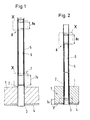
- FIG. 1 shows the partial area of a tube sheet 1 of a heat exchanger, which is not shown in further detail.
- a multiplicity of tubes 2 ends in the tube sheet, only one of which is shown.
- the tube 2 is connected to a cladding 4 of the tube sheet 1 via a weld seam 3.
- a sleeve 6 is introduced into the tube 2 and connected at its end regions 7, 8 by widening to an area of the tube 2 located above the tube plate 1.
- the sleeve 6 is expanded hydraulically in an area outside the tube sheet 1, for example, a different springback of the tube 2 and the sleeve 6 occurs, which is in a gap of expresses about 5 to 10 microns, which occurs at the widened end regions 7, 8 between the tube 2 and the sleeve 6 after the expansion process has ended.
- the sleeve 6 is widened with its one end area 7 in the area of the tube sheet 1 and with its other end area 8 in the area outside the tube sheet.
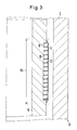
- FIG. 3 shown on a larger scale, shows the design of the end regions 7 and 8 according to FIG. 1 and of the end region 8 according to FIG. 2 (detail "X") of the sleeve 6 before it expands.
- the expansion area 8a (7a in FIG. 1) has an approximately 0.2 mm deep free rotation 9, into which a component made of a shape memory alloy formed as a sheet metal strip 10 is inserted in a spiral.
- An approximately 0.2 mm thick layer 11 covers the spiral component.
- the gap between tube 2 and the layer outside is approximately 0.3 mm before expansion. After the expansion process, which is not shown in FIG. 3, the springback described above takes place, which leads to a gap width of approximately 5 to 10 ⁇ m between the tube 2 and the sleeve 6.
- the property of the shape memory alloy is selected so that when the operating temperature of the heat exchanger has been reached it has expanded in such a way that a gap-bridging and sealing connection with the tube 2 is formed with the interposition of the layer 11.
- the layer 11 in addition to its corrosion-protecting cover, closes a space 12 between the spindle windings to prevent leakage.
- a leak medium could enter space 12 at one end and then along the spiral Windings that delimit space 12 penetrate the expansion area in the axial direction of the sleeve. If the corrosion-protecting coating can be dispensed with, the introduction of the layer 11 into the space 12 is sufficient to avoid leakage.
- the layer 11 thus does not overlap the metal strip 10.
- the expansion area 8a assigned to the end area 8 has at least one closed ring 13 made of a shape memory alloy.
- the leakage passage described with regard to the spiral configuration according to FIG. 3 cannot take place here.
- a layer 11 would therefore at best be required for corrosion protection purposes.
- the rings 13 can be formed both wire-shaped and as a sheet metal strip. It is only important that the change in thickness induced by the shape memory effect is dimensioned sufficiently large to reliably bridge the gap formed due to the springback when the predetermined temperature is reached.
- FIGS. 3 and 4 can be used for the details “X” according to FIGS. 1 and 2 (widening outside the tube sheet 1).
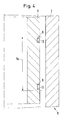
- the sleeve 6 extends with one end into the tube sheet 1, then it is designed in its expansion area 7a in accordance with FIG. 5.
- a half-section shows the sleeve 6 with its expansion area 7a on a larger scale before the expansion process.
- the sleeve 6 is provided with a collar 14 which represents the part with the lower surface hardness than that of the tube 2.
- a layer 15 is applied below the collar 14. She assigns one Profiling on and represents the part with the greater surface hardness than that of the pipe.
- the collar 14 and the layer 15 are drawn oversized.
- the collar 14 projects approximately 0.05-0.1 mm beyond the remaining outer surface of the sleeve 6 and has a width of approximately 10 mm.
- the preferably sprayed-on layer 15, like the collar 14, also projects 0.05 to 0.1 mm beyond the remaining lateral surface of the sleeve 6 and has a width of approximately 7 mm.
- the profile depth of the profiling of layer 15 is approximately 0.01 to 0.05 mm.
- the change in yield strength in the material of the hollow cylindrical part caused by compression simultaneously causes an increase in the non-positive connection between the sleeve 6 and the tube 2.
- the profiling of the layer 15, which has a greater hardness than the inner wall 2 penetrates so far (namely 0.01 to 0.05 mm) into the inner wall of the tube, as dictated by the deformation process of the collar 14 and thus brings about a positive connection between the sleeve and the tube.
- Relatively small expansion forces per unit area enable the connection to the pipe 2 to be achieved, since the large profile area means that a maximum penetration depth of 0.05 mm is sufficient for a reliable connection.
- the low expansion forces therefore also exclude pipe damage if the sleeve 6 is expanded above the tube sheet 1.
- the fine-pored structure of the profiling 16 is interrupted by ring-shaped components 13 made of a shape memory alloy, which are embedded in the outer surface of the sleeve 6 at predetermined intervals.
- the area provided with a profiling 16 has the same outer diameter as the components 13.
- the thickness of the components 13 is shown larger for better illustration. It is usually about 0.2 mm, so that these components can be designed as a sheet metal strip. After expansion of the sleeve and after reaching a predetermined temperature, the components 13 will bridge the gap caused by the springback and seal absolutely against leakage.
Abstract
Description
Die Erfindung betrifft eine metallische Hülse zur Überbrückung einer Leckagestelle eines Rohres, die mit Hilfe der Aufweittechnik an die Innenwandfläche des Rohres anlegbar ist.The invention relates to a metallic sleeve for bridging a leakage point of a pipe, which can be applied to the inner wall surface of the pipe using the expansion technique.
Eine derartige Hülse ist aus der EP-A-00 47 407 bekannt. Dort weist die Hülse im der Nähe ihres oberen und unteren Endes einen mit einer Zahnung versehenen Teilbereich auf. Nachdem in einem ersten Schritt durch hydraulische Aufweitung dieser Bereiche die Zahnung in die Rohrwand eingedrungen ist, wird in einem zweiten Schritt der zwischen den Zahnungen liegende Bereich ebenfalls hydraulisch aufgeweitet. Der dabei in axialer Richtung auftretende Schrumpfvorgang soll die Verbindung zwischen dem Rohr und der Hülse im Bereich der Verzahnung unterstützen.Such a sleeve is known from EP-A-00 47 407. There, the sleeve has a toothed portion near its upper and lower ends. After the teeth have penetrated into the tube wall in a first step by hydraulic widening of these areas, the area lying between the teeth is also hydraulically expanded in a second step. The shrinking process occurring in the axial direction is intended to support the connection between the tube and the sleeve in the region of the toothing.
Bei dem Aufweitvorgang entsteht aufgrund der unterschiedlichen elastischen Rückfederung der verformten Materialien, die unter anderem auf den unterschiedlichen Verformungswegen von Rohr und Hülse beruht, ein Spalt von ca. 5 bis 10 µm zwischen dem Rohr und der Hülse. Eine Leckage muß daher in geringen Mengen in Kauf genommen werden. Soll die Leckage vollständig unterbunden werden, ist seither die Verschweißung der Hülsenenden mit dem Rohr erforderlich.During the expansion process, there is a gap of approx. 5 to 10 µm between the tube and the sleeve due to the different elastic springback of the deformed materials, which is based, among other things, on the different deformation paths of the tube and the sleeve. Leakage must therefore be accepted in small quantities. If the leakage is to be completely prevented, the sleeve ends have to be welded to the pipe since then.
Die Schweißung stellt eine Wärmebehandlung dar, die zu unerwünschten Spannungen führen kann und außerdem den Zeitaufwand der Rohrreparatur erhöht. Ferner sind Korrosionserscheinungen im Spalt nicht abzusehen.The weld is a heat treatment that can lead to undesirable stresses and also increases the time required for pipe repair. There are also no signs of corrosion in the gap.
Ferner ist aus der deutschen Zeitschrift gwf-Gas/Erdgas (1975), Heft 10, Seite 412 bis 417 eine Einrichtung zur Sanierung von Stemmuffenleitungen bekannt. Im Bereich der Stemmmuffe wird die undichte Stelle mit Hilfe einer klebstoffbeschichteten Alu-Trägerfolie abgedichtet. Mit einer aufblasbaren Membrane wird die Alu-Folie bis zur Erzielung der Klebeverbindung an der Rohrinnenwand zur Anlage gebracht. Der Einsatz von Klebstoff gestattet die Verwendung des bekannten Verfahrens nur dort, wo der Klebstoff durch das in der Rohrleitung strömende Medium nicht angegriffen wird.Furthermore, from the German magazine gwf-Gas / Erdgas (1975), No. 10, pages 412 to 417, a device for the renovation of caulking pipes is known. In the area of the stem sleeve, the leak is sealed using an adhesive-coated aluminum carrier film. Using an inflatable membrane, the aluminum foil is brought into contact with the inner wall of the pipe until the adhesive connection is achieved. The use of adhesive allows the known method to be used only where the adhesive is not attacked by the medium flowing in the pipeline.
Es stellt sich die Aufgabe, eine metallische Hülse der eingangs genannten Art anzugeben, die ohne Verschweißung eine leckagedichte Verbindung mit dem Rohr ermöglicht und unabhängig von dem in der Rohrleitung strömenden Medium einsetzbar ist..It is the task of specifying a metallic sleeve of the type mentioned at the outset which enables a leak-tight connection to the pipe without welding and can be used regardless of the medium flowing in the pipe.
Gelöst wird diese Aufgabe erfindungsgemäß dadurch, daß die Hülse umfangseitig mehrere Bauteile aus einer Formgedächtnislegierung trägt, die beim Erreichen einer vorgebbaren Temperatur eine Dichtung zwischen der Hülse und dem Rohr darstellen.This object is achieved according to the invention in that the sleeve carries a plurality of components made of a shape memory alloy on the circumference, which, when a predeterminable temperature is reached, form a seal between the sleeve and the tube.
Der Bauteil aus einer Formgedächtnislegierung führt die Aufweitbewegung der Hülse mit aus, so daß nach Beendigung des Aufweitvorganges und der erfolgten Rückfederung ein Spalt zwischen der Hülse bzw. dem Bauteil aus der Formgedächtnislegierung und dem Rohr vorhanden ist. Bei Erwärmen des Rohres auf eine vorgegebene Temperatur deutlich unterhalb der Betriebstemperatur wird die auf diese Betriebstemperatur eingestellte Formgedächtnislegierung aufgrund des Formgedächtniseffektes aufgeweitet, um eine Dichtung zwischen Hülse und Rohr herzustellen.The component made of a shape memory alloy also carries out the expansion movement of the sleeve, so that after the expansion process has ended and the springback has taken place, a gap is present between the sleeve or the component made of the shape memory alloy and the tube. When the tube is heated to a predetermined temperature significantly below the operating temperature, the shape memory alloy set to this operating temperature is expanded due to the shape memory effect in order to produce a seal between the sleeve and the tube.
Eine weitere Ausbildung sieht vor, daß jeweils ein Baueil an den Endbereichen der Hülse angeordnet ist und beim Erreichen einer vorgebbaren Temperatur eine Dichtung zwischen der Hülse und dem Rohr darstellt, daß die Hülse an ihrem dem Bauteil abgewandten Ende einen Aufweitbereich besitzt, der aus einen Teil mit einer geringeren Oberflächenhärte und einem Teil mit einer größeren Oberflächenhärte als der des Rohres besteht und wobei der Teil mit der größeren Oberflächenhärte mit einer Profilierung versehen ist.A further embodiment provides that in each case a component is arranged at the end regions of the sleeve and, when a predeterminable temperature is reached, a seal between the sleeve and the tube represents that the sleeve has an expansion area at its end facing away from the component, which part with a lower surface hardness and a part with a greater surface hardness than that of the pipe and the part with the greater surface hardness is provided with a profile.
Diese Lösung findet dann Verwendung, wenn die Hülse an ihrem einen Ende in ein außerhalb eines Rohrbodens reichendes Rohrteil und mit seinem anderen Ende in ein in einen Rohrboden eines Wärmetauschers reichendes Rohrteil eingebracht werden muß. Die Unterschiede der Rückfederung im Bereich des Rohrbodens sind vernachlässigbar, so daß dort der Einsatz eines Bauteiles aus einer Formgedächtnislegierung nicht erforderlich ist.This solution is used when the sleeve has to be inserted at one end into a tube part extending outside a tube sheet and at the other end into a tube part extending into a tube sheet of a heat exchanger. The differences in springback in the area of the tube sheet are negligible, so that the use of a component made of a shape memory alloy is not necessary there.
Anhand einiger Ausführungsbeispiele wird die erfindungsgemäße Hülse und deren vorteilhafter Einsatz beschrieben.The sleeve according to the invention and its advantageous use are described on the basis of a few exemplary embodiments.
Dabei zeigen die
- Fig. 1
- eine in den Rohrbereich oberhalb des Rohrbodens eines Wärmetauschers eingesetzte Hülse,
- Fig. 2
- eine im Bereich des Rohrbodens und oberhalb des Rohrbodens eingesetzte Hülse,
- Fig. 3
- die Einzelheiten "X" der
Figuren 1 und 2 vor dem Aufweitvorgang in einem größeren Maßstab, - Fig. 4
- eine andere Ausbildung der Ausführung nach
Figur 3 und - Fig. 5
- die Einzelheit "Y" der
Figur 2 in einem größeren Maßstab, - Fig. 6
- . eine andere Ausbildung der Ausführung nach
Figur 5.
- Fig. 1
- a sleeve inserted into the tube area above the tube sheet of a heat exchanger,
- Fig. 2
- a sleeve inserted in the area of the tube sheet and above the tube sheet,
- Fig. 3
- the details "X" of Figures 1 and 2 before the expansion process on a larger scale,
- Fig. 4
- another embodiment of the embodiment of Figure 3 and
- Fig. 5
- the detail "Y" of Figure 2 on a larger scale,
- Fig. 6
- . another embodiment of the embodiment of Figure 5.
Die Figur 1 zeigt den Teilbereich eines Rohrbodens 1 eines nicht weiter dargestellten Wärmetauschers. In dem Rohrboden endet eine Vielzahl von Rohren 2, wovon nur eines dargestellt ist. Das Rohr 2 ist über eine Schweißnaht 3 mit einer Plattierung 4 des Rohrbodens 1 verbunden. Zur Überbrückung einer Leckagestelle 5 des Rohres 2 ist eine Hülse 6 in das Rohr 2 eingebracht und an ihren Endbereichen 7, 8 durch Aufweiten mit einem oberhalb des Rohrbodens 1 befindlichen Bereich des Rohres 2 verbunden. Insbesondere wenn die Hülse 6 in einem Bereich außerhalb des Rohrbodens 1 zum Beispiel hydraulisch aufgeweitet wird, tritt eine unterschiedliche Rückfederung von Rohr 2 und Hülse 6 auf, die sich in einem Spalt von ca. 5 bis 10 µm ausdrückt, der sich an den aufgeweiteten Endbereichen 7, 8 zwischen dem Rohr 2 und der Hülse 6 nach der Beendigung des Aufweitvorganges einstellt.FIG. 1 shows the partial area of a
Nach der Figur 2 ist die Hülse 6 mit ihrem einen Endbereich 7 im Bereich des Rohrbodens 1 und mit ihrem anderen Endbereich 8 in Bereich außerhalb des Rohrbodens aufgeweitet.According to FIG. 2, the
Die in einem größeren Maßstab dargestellte Figur 3 zeigt die Ausbildung der Endbereiche 7 und 8 nach der Figur 1 und des Endbereiches 8 nach der Figur 2 (Einzelheit "X") der Hülse 6 vor ihrer Aufweitung. Der Aufweitbereich 8a (7a in Figur 1) weist eine ca. 0,2 mm tiefe Freidrehung 9 auf, in die ein als Blechband 10 ausgebildetes Bauteil aus einer Formgedächtnislegierung spiralförmig eingelegt ist. Eine ca. 0,2 mm dicke Schicht 11 überdeckt den spiralförmigen Bauteil. Der Spalt zwischen den Rohr 2 und der Schichtaußenseite beträgt vor dem Aufweiten ca. 0,3 mm. Nach dem Aufweitvorgang, der in der Figur 3 nicht dargestellt ist, erfolgt die vorgehend erläuterte Rückfederung, die zu einer Spaltbreite von ca. 5 bis 10 µm zwischen dem Rohr 2 und der Hülse 6 führt. Die Eigenschaft der Formgedächtnislegierung ist so gewählt, daß sie sich bei Erreichen der Betriebstemperatur des Wärmetauschers derart ausgedehnt hat, daß unter Zwischenlage der Schicht 11 eine den Spalt überbrückende und dichtende Verbindung mit dem Rohr 2 entsteht. Die Schicht 11 bewirkt bei einen als Blechband 10 ausgebildeten Bauteil aus der Formgedächtnislegierung neben dessen korrosionsschützende Abdeckung ein Verschluß eines Raumes 12 zwischen den Spindelwindungen gegen Leckageeintritt. Ein Leckagemedium könnte zum Beispiel in den Raum 12 an einem Ende eindringen und dann entlang der spiralförmigen Windungen, die den Raum 12 begrenzen, den Aufweitbereich in Achsrichtung der Hülse durchsetzen. Kann auf den korrosionsschützenden Überzug verzichtet werden, so reicht das Einbringen der Schicht 11 lediglich in den Raum 12 zur Vermeidung eines Leckagedurchtrittes aus. Die Schicht 11 übergreift dabei also nicht das Blechband 10.FIG. 3, shown on a larger scale, shows the design of the
Nach der Ausbildung gemäß der Figur 4 weist der dem Endbereich 8 zugeordnete Aufweitbereich 8a wenigstens einen geschlossenen Ring 13 aus einer Formgedächtnislegierung auf. Der hinsichtlich der spiralförmigen Ausbildung nach Figur 3 beschriebene Leckagedurchtritt kann hier nicht erfolgen. Eine Schicht 11 wäre daher beim Ausführungsbeispiel nach Figur 4 bestenfalls zu Korrosionsschutzzwecken erforderlich. Die Ringe 13 können sowohl drahtförmig als auch als Blechband ausgebildet werden. Von Bedeutung ist lediglich, daß ihre durch den Formgedächtniseffekt induzierte Dickenänderung ausreichend groß bemessen ist, um bei Erreichen der vorgegebenen Temperatur den aufgrund der Rückfederung entstandenen Spalt zuverlässig zu überbrücken.According to the design according to FIG. 4, the
Die Ausbildungen nach den Figuren 3 und 4 sind für die Einzelheiten "X" nach den Figuren 1 und 2 (Aufweitung außerhalb des Rohrbodens 1) einsetzbar. Erstreckt sich die Hülse 6 mit ihrem einen Ende in den Rohrboden 1, so ist sie in ihrem Aufweitbereich 7a entsprechend der Figur 5 ausgebildet. Ein Halbschnitt zeigt nach dieser Figur 5 in einem größeren Maßstab die Hülse 6 mit ihrem Aufweitbereich 7a vor dem Aufweitvorgang. Innerhalb des Aufweitbereiches 7a ist die Hülse 6 mit einem Bund 14 versehen, der den Teil mit der geringeren Oberflächenhärte als der des Rohres 2 darstellt. Unterhalb des Bundes 14 ist eine Schicht 15 aufgetragen. Sie weist eine Profilierung auf und stellt den Teil mit der größeren Oberflächenhärte als der des Rohres dar. Um die Mantelflächenausbildung des Aufweitbereiches 7a besser darstellen zu können, sind der Bund 14 und die Schicht 15 überdimensioniert gezeichnet. In Wirklichkeit ragt der Bund 14 etwa 0,05 - 0,1 mm über die restliche Mantelfläche der Hülse 6 hinaus und weist eine Breite von ca. 10 mm auf. Auch die vorzugsweise aufgespritzte Schicht 15 ragt ebenso wie der Bund 14 0,05 bis 0,1 mm über die restliche Mantelfläche der Hülse 6 hinaus und weist eine Breite von ca. 7 mm auf. Die Profiltiefe der Profilierung der Schicht 15 beträgt ca. 0,01 bis 0,05 mm. Beim Aufweitvorgang wird die Materialmasse des Bundes 14 derart gestaucht, daß er praktisch nicht mehr vorhanden ist. Die durch Stauchung enstandene Streckgrenzenänderung im Werkstoff des hohlzylindrischen Teiles bewirkt gleichzeitig eine Erhöhung der kraftschlüssigen Verbindung zwischen der Hülse 6 und dem Rohr 2. Beim Aufweitvorgang dringt die eine größere Härte als die Innenwand 2 aufweisende Profilierung der Schicht 15 so weit (nämlich 0,01 bis 0,05 mm) in die Innenwand des Rohres ein, wie es durch den Verformungsvorgang des Bundes 14 vorgegeben ist und bewirkt somit einen Formschluß zwischen Hülse und Rohr.The designs according to FIGS. 3 and 4 can be used for the details “X” according to FIGS. 1 and 2 (widening outside the tube sheet 1). If the
Die als Halbschnitt dargestellte Figur 6 läßt in einem größeren Maßstab die feinporige Struktur einer Profilierung 16 erkennen, die in Form einer kreuzförmig übereinander laufenden Rändelung ausgeführt sein kann. Durch relative kleine Aufweitkräfte pro Flächeneinheit gelingt die Verbindung mit dem Rohr 2, da wegen der großen Profilfläche eine Eindringtiefe von maximal 0,05 mm für eine zuverlässige Verbindung ausreicht. Die geringen Aufweitkräfte schließen daher auch Rohrschäden aus, wenn die Hülse 6 oberhalb des Rohrbodens 1 aufgeweitet wird. Die feinporige Struktur der Profilierung 16 ist durch ringförmige Bauteile 13 aus einer Formgedächtnislegierung unterbrochen, die in vorgebaren Abständen in die Mantelfläche der Hülse 6 eingelassen sind. Der mit einer Profilierung 16 versehene Bereich weist denselben Außendurchmesser auf wie die Bauteile 13. Die Dicke der Bauteile 13 ist zur besseren Darstellung größer dargestellt. Sie beträgt in der Regel ca. 0,2 mm, so daß diese Bauteile als Blechband ausgebildet sein können. Nach erfolgter Aufweitung der Hülse und nach Erreichen einer vorgegebenen Temperatur werden die Bauteile 13 den durch die Rückfederung bedingten Spalt überbrücken und absolut gegen Leckage abdichten.FIG. 6, shown as a half-section, shows on a larger scale the fine-pored structure of a
Claims (8)
Applications Claiming Priority (4)
| Application Number | Priority Date | Filing Date | Title |
|---|---|---|---|
| DE19904008252 DE4008252A1 (en) | 1990-03-15 | 1990-03-15 | Metal sleeve for pipe leakage point - consists of ring around sleeve ends, recess, with coated spirals |
| DE4008252 | 1990-03-15 | ||
| DE19904011136 DE4011136C1 (en) | 1990-04-06 | 1990-04-06 | Sleeve for sealing leaking pipe - has rings of shape retaining alloy spaced along periphery of sleeve |
| DE4011136 | 1990-04-06 |
Publications (2)
| Publication Number | Publication Date |
|---|---|
| EP0446841A1 true EP0446841A1 (en) | 1991-09-18 |
| EP0446841B1 EP0446841B1 (en) | 1994-10-12 |
Family
ID=25891151
Family Applications (1)
| Application Number | Title | Priority Date | Filing Date |
|---|---|---|---|
| EP91103698A Expired - Lifetime EP0446841B1 (en) | 1990-03-15 | 1991-03-11 | Metallic sleeve for bridging a leakage in a pipe |
Country Status (5)
| Country | Link |
|---|---|
| EP (1) | EP0446841B1 (en) |
| JP (1) | JPH04219590A (en) |
| KR (1) | KR910016401A (en) |
| DE (1) | DE59103194D1 (en) |
| ES (1) | ES2064787T3 (en) |
Cited By (7)
| Publication number | Priority date | Publication date | Assignee | Title |
|---|---|---|---|---|
| DE4243213C1 (en) * | 1992-12-19 | 1994-01-20 | Bbc Reaktor Gmbh | Fixing sealing socket in tube - using several rings made of shape memory alloy which can only bridge over reduced gap width |
| DE4311674C1 (en) * | 1993-04-08 | 1994-04-21 | Bbc Reaktor Gmbh | Seal at leakage point between pipe and coaxial sleeve - has two expanding rings in opposing directions with retainer covering both |
| EP0607052A2 (en) * | 1993-01-15 | 1994-07-20 | Babcock Construction Limited | Method and apparatus of effecting a repair to a metal tube |
| DE4433501A1 (en) * | 1994-09-20 | 1996-03-21 | Siemens Ag | Repair sleeve and method for repairing a heat exchanger tube |
| FR2726885A1 (en) * | 1994-11-15 | 1996-05-15 | Framatome Sa | RESISTANT AND WATERPROOF FIXING METHOD OF A CUFF INSIDE A METAL TUBE AND REPAIR CUFF OF A METAL TUBE |
| WO1997021956A2 (en) * | 1995-12-15 | 1997-06-19 | Westinghouse Electric Corporation | System and method for stabilizing a heat exchanger tube |
| WO1999047843A2 (en) | 1998-03-17 | 1999-09-23 | Siemens Aktiengesellschaft | Tube having an expansion area and method for producing such a tube |
Citations (5)
| Publication number | Priority date | Publication date | Assignee | Title |
|---|---|---|---|---|
| EP0137984A2 (en) * | 1983-10-14 | 1985-04-24 | Lummus Crest S.A.R.L. | Tube repair insert for steam generator |
| EP0248728A1 (en) * | 1986-06-04 | 1987-12-09 | Framatome | Method for resistantly and tightly fixing a hollow cylindrical element at the inside of a tube, and cylindrical element for carrying out this method |
| US4723578A (en) * | 1985-06-24 | 1988-02-09 | Combustion Engineering, Inc. | Steam generator tube repair method and assembly |
| FR2608727A1 (en) * | 1986-12-23 | 1988-06-24 | Souriau & Cie | Device for plugging a hollow body comprising an element made from a material with shape memory |
| EP0291003A1 (en) * | 1987-05-15 | 1988-11-17 | ABB Reaktor GmbH | Hollow plag for sealing a heat exchanger tube |
Family Cites Families (1)
| Publication number | Priority date | Publication date | Assignee | Title |
|---|---|---|---|---|
| US4368571A (en) * | 1980-09-09 | 1983-01-18 | Westinghouse Electric Corp. | Sleeving method |
-
1991
- 1991-03-11 ES ES91103698T patent/ES2064787T3/en not_active Expired - Lifetime
- 1991-03-11 DE DE59103194T patent/DE59103194D1/en not_active Expired - Fee Related
- 1991-03-11 EP EP91103698A patent/EP0446841B1/en not_active Expired - Lifetime
- 1991-03-12 KR KR1019910003939A patent/KR910016401A/en not_active Application Discontinuation
- 1991-03-15 JP JP3075659A patent/JPH04219590A/en active Pending
Patent Citations (5)
| Publication number | Priority date | Publication date | Assignee | Title |
|---|---|---|---|---|
| EP0137984A2 (en) * | 1983-10-14 | 1985-04-24 | Lummus Crest S.A.R.L. | Tube repair insert for steam generator |
| US4723578A (en) * | 1985-06-24 | 1988-02-09 | Combustion Engineering, Inc. | Steam generator tube repair method and assembly |
| EP0248728A1 (en) * | 1986-06-04 | 1987-12-09 | Framatome | Method for resistantly and tightly fixing a hollow cylindrical element at the inside of a tube, and cylindrical element for carrying out this method |
| FR2608727A1 (en) * | 1986-12-23 | 1988-06-24 | Souriau & Cie | Device for plugging a hollow body comprising an element made from a material with shape memory |
| EP0291003A1 (en) * | 1987-05-15 | 1988-11-17 | ABB Reaktor GmbH | Hollow plag for sealing a heat exchanger tube |
Non-Patent Citations (3)
| Title |
|---|
| PATENT ABSTRACTS OF JAPAN vol. 11, no. 1 (M-550)(2448) 07 Februar 1987, & JP-A-61 180895 (HITACHI) 13 August 1986, * |
| PATENT ABSTRACTS OF JAPAN vol. 12, no. 428 (M-762)(3275) 11 November 1988, & JP-A-63 161395 (SUMITOMO METAL) 05 Juli 1988, * |
| PATENT ABSTRACTS OF JAPAN vol. 9, no. 29 (M-356)(1752) 07 Februar 1985, & JP-A-59 173696 (HITACHI SEISAKUSHO) 01 Oktober 1984, * |
Cited By (12)
| Publication number | Priority date | Publication date | Assignee | Title |
|---|---|---|---|---|
| DE4243213C1 (en) * | 1992-12-19 | 1994-01-20 | Bbc Reaktor Gmbh | Fixing sealing socket in tube - using several rings made of shape memory alloy which can only bridge over reduced gap width |
| EP0607052A2 (en) * | 1993-01-15 | 1994-07-20 | Babcock Construction Limited | Method and apparatus of effecting a repair to a metal tube |
| EP0607052A3 (en) * | 1993-01-15 | 1994-08-03 | Babcock Constr Ltd | |
| DE4311674C1 (en) * | 1993-04-08 | 1994-04-21 | Bbc Reaktor Gmbh | Seal at leakage point between pipe and coaxial sleeve - has two expanding rings in opposing directions with retainer covering both |
| DE4433501A1 (en) * | 1994-09-20 | 1996-03-21 | Siemens Ag | Repair sleeve and method for repairing a heat exchanger tube |
| FR2726885A1 (en) * | 1994-11-15 | 1996-05-15 | Framatome Sa | RESISTANT AND WATERPROOF FIXING METHOD OF A CUFF INSIDE A METAL TUBE AND REPAIR CUFF OF A METAL TUBE |
| EP0713049A1 (en) * | 1994-11-15 | 1996-05-22 | Framatome | Device for resistantly and tightly fixing a sleeve on the inner surface of a metal pipe and repair sleeve for a metal pipe |
| WO1997021956A2 (en) * | 1995-12-15 | 1997-06-19 | Westinghouse Electric Corporation | System and method for stabilizing a heat exchanger tube |
| WO1997021956A3 (en) * | 1995-12-15 | 1997-08-28 | Westinghouse Electric Corp | System and method for stabilizing a heat exchanger tube |
| WO1999047843A2 (en) | 1998-03-17 | 1999-09-23 | Siemens Aktiengesellschaft | Tube having an expansion area and method for producing such a tube |
| DE19811599A1 (en) * | 1998-03-17 | 1999-09-30 | Siemens Ag | Pipe with an expansion area |
| DE19811599C2 (en) * | 1998-03-17 | 2002-01-10 | Framatome Anp Gmbh | Pipe with an expansion area |
Also Published As
| Publication number | Publication date |
|---|---|
| JPH04219590A (en) | 1992-08-10 |
| KR910016401A (en) | 1991-11-05 |
| EP0446841B1 (en) | 1994-10-12 |
| ES2064787T3 (en) | 1995-02-01 |
| DE59103194D1 (en) | 1994-11-17 |
Similar Documents
| Publication | Publication Date | Title |
|---|---|---|
| EP0462530B1 (en) | Method for sealing a pipe with a sleeve | |
| DE4406167C2 (en) | Method for achieving a tight connection between a tube and a sleeve | |
| DE3135966C2 (en) | Process for the manufacture of multilayer screw sutures | |
| DE3716328C2 (en) | ||
| EP0446841A1 (en) | Metallic sleeve for bridging a leakage in a pipe | |
| DE1514958A1 (en) | Nuclear reactor fuel element and method and device for closing a protective tube for this | |
| DE4008252C2 (en) | ||
| EP1922509B1 (en) | Method for tightly joining two end sections of corrugated pipes and device for carrying out this method | |
| DE3130272A1 (en) | Device for fixing a pipeline | |
| CH657908A5 (en) | COMPENSATOR FOR PIPELINES. | |
| DE3830439A1 (en) | METHOD FOR PRODUCING A LEAK DETECTION AND / OR WARM INSULATION GAP BETWEEN A WALL AND COVERING PANELS AND COVERING PANELS USED THEREFOR | |
| DE4011136C1 (en) | Sleeve for sealing leaking pipe - has rings of shape retaining alloy spaced along periphery of sleeve | |
| DE2362926A1 (en) | PROCEDURE FOR CONNECTING PIPES AND SOCKET FOR CARRYING OUT THE PROCEDURE | |
| EP0332954A1 (en) | Corrosion proof metallic joining element | |
| EP0447391B1 (en) | Obturating element for sealing a defective heat-exchanger pipe | |
| DE19513604A1 (en) | Producing air-tight joints between two tubes of different material | |
| EP0687849A1 (en) | Method of limiting fast crack propagation in plastic pipes and pipes obtained by such method | |
| DE3107310A1 (en) | TUBULAR PULL-OVER SLEEVE FOR THE CONNECTING AREA OF TUBE SHEETS OF A HEAT-INSULATED TUBE | |
| DE3534241A1 (en) | Process for producing an insulation of in situ polyurethane foam for pipelines, containers and columns | |
| EP0350802A1 (en) | Method for reconstructing pipe-lines | |
| DE10207199A1 (en) | Sealing leak in metal pipe transporting crude oil or gas comprises positioning metal plate over leak, attaching explosive to plate and detonating explosive to weld plate to pipe and seal leak | |
| DE3600302C2 (en) | ||
| DE2528739C2 (en) | Method for pressure-tight fastening of pipes to a pipe disc | |
| DE2924376A1 (en) | Fixing of tube in tube plate by expansion of tube end - where expanding bush is used to prevent damage to polymer coating in bore of tube | |
| DE3826078A1 (en) | Process for connecting district-heating pipes |
Legal Events
| Date | Code | Title | Description |
|---|---|---|---|
| PUAI | Public reference made under article 153(3) epc to a published international application that has entered the european phase |
Free format text: ORIGINAL CODE: 0009012 |
|
| AK | Designated contracting states |
Kind code of ref document: A1 Designated state(s): BE CH DE ES FR GB LI NL SE |
|
| 17P | Request for examination filed |
Effective date: 19911008 |
|
| 17Q | First examination report despatched |
Effective date: 19921105 |
|
| GRAA | (expected) grant |
Free format text: ORIGINAL CODE: 0009210 |
|
| AK | Designated contracting states |
Kind code of ref document: B1 Designated state(s): BE CH DE ES FR GB LI NL SE |
|
| ET | Fr: translation filed | ||
| REF | Corresponds to: |
Ref document number: 59103194 Country of ref document: DE Date of ref document: 19941117 |
|
| GBT | Gb: translation of ep patent filed (gb section 77(6)(a)/1977) |
Effective date: 19941103 |
|
| EAL | Se: european patent in force in sweden |
Ref document number: 91103698.6 |
|
| REG | Reference to a national code |
Ref country code: ES Ref legal event code: FG2A Ref document number: 2064787 Country of ref document: ES Kind code of ref document: T3 |
|
| PGFP | Annual fee paid to national office [announced via postgrant information from national office to epo] |
Ref country code: NL Payment date: 19950331 Year of fee payment: 5 |
|
| PLBE | No opposition filed within time limit |
Free format text: ORIGINAL CODE: 0009261 |
|
| STAA | Information on the status of an ep patent application or granted ep patent |
Free format text: STATUS: NO OPPOSITION FILED WITHIN TIME LIMIT |
|
| 26N | No opposition filed | ||
| PGFP | Annual fee paid to national office [announced via postgrant information from national office to epo] |
Ref country code: GB Payment date: 19960130 Year of fee payment: 6 |
|
| PGFP | Annual fee paid to national office [announced via postgrant information from national office to epo] |
Ref country code: SE Payment date: 19960131 Year of fee payment: 6 |
|
| PGFP | Annual fee paid to national office [announced via postgrant information from national office to epo] |
Ref country code: CH Payment date: 19960222 Year of fee payment: 6 |
|
| PGFP | Annual fee paid to national office [announced via postgrant information from national office to epo] |
Ref country code: ES Payment date: 19960329 Year of fee payment: 6 |
|
| PG25 | Lapsed in a contracting state [announced via postgrant information from national office to epo] |
Ref country code: NL Effective date: 19961001 |
|
| NLV4 | Nl: lapsed or anulled due to non-payment of the annual fee |
Effective date: 19961001 |
|
| PG25 | Lapsed in a contracting state [announced via postgrant information from national office to epo] |
Ref country code: GB Effective date: 19970311 |
|
| PG25 | Lapsed in a contracting state [announced via postgrant information from national office to epo] |
Ref country code: SE Effective date: 19970312 Ref country code: ES Free format text: LAPSE BECAUSE OF NON-PAYMENT OF DUE FEES Effective date: 19970312 |
|
| PG25 | Lapsed in a contracting state [announced via postgrant information from national office to epo] |
Ref country code: LI Effective date: 19970331 Ref country code: CH Effective date: 19970331 |
|
| GBPC | Gb: european patent ceased through non-payment of renewal fee |
Effective date: 19970311 |
|
| REG | Reference to a national code |
Ref country code: CH Ref legal event code: PL |
|
| EUG | Se: european patent has lapsed |
Ref document number: 91103698.6 |
|
| PGFP | Annual fee paid to national office [announced via postgrant information from national office to epo] |
Ref country code: FR Payment date: 19980127 Year of fee payment: 8 |
|
| PGFP | Annual fee paid to national office [announced via postgrant information from national office to epo] |
Ref country code: BE Payment date: 19980212 Year of fee payment: 8 |
|
| PGFP | Annual fee paid to national office [announced via postgrant information from national office to epo] |
Ref country code: DE Payment date: 19980227 Year of fee payment: 8 |
|
| PG25 | Lapsed in a contracting state [announced via postgrant information from national office to epo] |
Ref country code: BE Free format text: LAPSE BECAUSE OF NON-PAYMENT OF DUE FEES Effective date: 19990331 |
|
| REG | Reference to a national code |
Ref country code: ES Ref legal event code: FD2A Effective date: 19990503 |
|
| BERE | Be: lapsed |
Owner name: ABB REAKTOR G.M.B.H. Effective date: 19990331 |
|
| PG25 | Lapsed in a contracting state [announced via postgrant information from national office to epo] |
Ref country code: FR Free format text: LAPSE BECAUSE OF NON-PAYMENT OF DUE FEES Effective date: 19991130 |
|
| REG | Reference to a national code |
Ref country code: FR Ref legal event code: ST |
|
| PG25 | Lapsed in a contracting state [announced via postgrant information from national office to epo] |
Ref country code: DE Free format text: LAPSE BECAUSE OF NON-PAYMENT OF DUE FEES Effective date: 20000101 |