EP0446544A2 - Verfahren und Vorrichtung zur Erkennung verschiedener Elemente gängiger Grösse, insbesondere für Fensterrahmen während der Fabrikation - Google Patents
Verfahren und Vorrichtung zur Erkennung verschiedener Elemente gängiger Grösse, insbesondere für Fensterrahmen während der Fabrikation Download PDFInfo
- Publication number
- EP0446544A2 EP0446544A2 EP90403482A EP90403482A EP0446544A2 EP 0446544 A2 EP0446544 A2 EP 0446544A2 EP 90403482 A EP90403482 A EP 90403482A EP 90403482 A EP90403482 A EP 90403482A EP 0446544 A2 EP0446544 A2 EP 0446544A2
- Authority
- EP
- European Patent Office
- Prior art keywords
- type
- machine
- detector
- stop
- probe
- Prior art date
- Legal status (The legal status is an assumption and is not a legal conclusion. Google has not performed a legal analysis and makes no representation as to the accuracy of the status listed.)
- Withdrawn
Links
- 238000000034 method Methods 0.000 title claims description 9
- 238000004519 manufacturing process Methods 0.000 title 1
- 239000000523 sample Substances 0.000 claims description 16
- 210000000056 organ Anatomy 0.000 claims description 4
- 230000001419 dependent effect Effects 0.000 claims description 2
- 238000006073 displacement reaction Methods 0.000 description 2
- 230000001939 inductive effect Effects 0.000 description 2
- 238000001514 detection method Methods 0.000 description 1
- 230000000694 effects Effects 0.000 description 1
- 229910052751 metal Inorganic materials 0.000 description 1
Images


Classifications
-
- G—PHYSICS
- G01—MEASURING; TESTING
- G01B—MEASURING LENGTH, THICKNESS OR SIMILAR LINEAR DIMENSIONS; MEASURING ANGLES; MEASURING AREAS; MEASURING IRREGULARITIES OF SURFACES OR CONTOURS
- G01B5/00—Measuring arrangements characterised by the use of mechanical techniques
- G01B5/20—Measuring arrangements characterised by the use of mechanical techniques for measuring contours or curvatures
- G01B5/207—Measuring arrangements characterised by the use of mechanical techniques for measuring contours or curvatures using a plurality of fixed, simultaneously operating transducers
Definitions
- the present invention relates to a method and a device for recognizing elements of standardized size.
- this device is intended to equip a processing machine for window frames or French windows.
- the problem in such machines is to identify which type of chassis is brought to the machine in order to control the corresponding equipment characteristics, each type having standard dimension characteristics.
- the solution is therefore to determine, using a simple and reliable device, the appropriate dimension of the element and to transmit this information, possibly modified by a prerecorded parameter, to the machine control device.
- This device more particularly adapted to a window frame equipment machine can obviously be used in any application where it is necessary to locate and recognize elements in order to treat them in correspondence.
- the invention proposes a recognition device comprising a feeler and a corresponding detector, the association of these two elements making it possible by logical deduction to determine the type of the element identified, and in particular in the case of an equipment machine. frame, type of leaf and opening direction. It would have been possible to carry out a probe for each of the elements to locate, but that would have led to multiply and complicate the computer settings. Thanks to the invention, the same effects are obtained by a limited number of combinations.
- the present invention proposes a method for recognizing elements of different type, each type having a dimension predetermined.
- This method is remarkable in that a set of at least one concealing member is moved and positioned as a function of the dimension of the type of element by means of a feeler device, this first set cooperating with a set of at minus a fixed sensor, the organ (s) obscuring the sensor (s) in several combinations, thus providing information dependent on the dimension identified and specific to the type of element present.
- the positioning of the concealment members and of the sensors is defined according to the number and dimensions of the elements to be located.
- the information is modified by a prerecorded parameter depending on the type of element and from this modified information result the processing parameters of the element.
- the invention provides a device for recognizing elements of different types, each type having a predetermined dimension; this device comprises a stop against which is positioned one side of the element, a movable probe comprising a movable stop intended to come into contact with the other side of the element and a detector consisting of a set of at least one occultation member integral with the probe and a set of at least one fixed sensor.
- the detector comprises an axis supported in translation by fixed bearings, this axis integrally supporting the occultation organ (s) and being integral with the probe.
- the detector comprises a second axis parallel to the first, supported by the same bearings and intended for the stiffening of the detection mechanism.
- the preferred application of this recognition device is the equipment of a machine for working with window frame frames or French windows, in order to determine the type of frame to be treated; according to this particular application, the stop is located at a reference angle on which is brought one side of the upright of a leaf frame by means of the machine feed device, the probe is controlled in translation relative to the fixed frame of the machine to come into contact with the other side of the upright of the frame, the detector is supported by a support piece secured to the chassis of the machine.
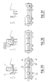
- FIG. 1 is a partial front sectional view of the device according to the invention fitted to a window treatment machine for window sashes;
- FIG. 2 is a sectional view along AA of the device according to the invention fitted to a window casement processing machine;
- FIGS. 3A to 3F are schematic views of operation of the device opposite the different types of amounts of leaf frames to identify.
- the figures illustrate the recognition device and the method for recognizing elements of different types, applied to the recognition of uprights of window sash frames or French windows.
- the device is therefore installed on a frame processing machine, for example a seal-laying machine, a fitting fittings or any other automatic machine for equipping or processing leaf frames.
- Figures 1 and 2 show more precisely the recognition device according to the invention.
- This device comprises a first stop 6 movable relative to the frame M of the machine, against which the upright is brought into contact 1.
- the leaf frame is brought into abutment on a fixed bank 45 which constitutes one of the organs of the device feeding or feeding frames on the machine.
- This stop 6 determines the reference angle of the frame and the clamping of the latter on the machine table is completed by holding elements placed for example on the other upright of the frame.
- the stop 6 is movable around an axis and provided with a counterweight 61 which returns it to its active projecting position automatically once the leaf frame has passed.
- the leaf frame is arranged on the machine table with its inner face placed on the table and its outer face facing up, referring to a leaf intended to be opened inwards.
- the upper crossmember 2 adjoins the bank 45.
- the recognition device also includes a probe 3 and a detector 4.
- the probe 3 is mounted mobile on the machine, by means of a translation device for example by rails or the like and is preferably driven by a preferably pneumatic device described below. Projecting from the plane of the machine table, a stop element 31 is therefore displaced to form a second contact on the other side of the upright 1. The thickness of this upright 1 is therefore determined by the distance separating the first stop 6 and the second movable stop 31.
- the detector 4 which is mounted near the probe 3 on the frame M of the machine comprises a movable part connected in displacement to the probe 3 and a fixed part secured to the frame of the machine.
- the constitution of the detector 4 is particularly visible in FIG. 2.
- the detector 4 is therefore mounted on a support piece 41 secured to the chassis M of the machine.
- the first horizontal axis 42 supports the assembly of at least one concealment member 50, this or these concealment members 50 being integral with the axis 42.
- the detector 4 also comprises an assembly of at least one sensor 60 fixedly mounted on the fixed part of the detector 4.
- the axis 42 supports the concealment members 50 and the axis 43 is the driving axis of the translation, on which the pneumatic energy acts, this axis being arranged in a valve valve system inside the detector. 4.
- the concealment member (s) 50 are displaced and positioned as a function of the displacement and of the positioning of the movable stop 31 and depending on the dimensions of the upright 1, obscure or not the light beam, magnetic or otherwise, of the sensor (s) 60 .
- the purpose of the device is to determine the type of leaf and its type of opening. In other words, it is a question of determining the type of the leaf and of locating if it is a right or left frame according to the type in order to control in the case of a joint laying machine l '' location for fitting the joint (on 4 or 3 sides), in the case of a fitting machine the location and the type of fitting to be fitted ...
- FIGS. 3A- to 3F represent in a schematic front view the first stop 6 and the second movable stop 31 of the probe 3, in transverse contact with an upright 1 of the leaf frame and in schematic view from above the detector 4 with the axis 42 with the concealing members 50 translated on the bearings 41 ′ and 41 "and the fixed sensors 60.
- FIG. 3A illustrates the maximum opening position of the probe 31 and the corresponding positions of the concealment members 50.
- FIG. 3B an upright with index cards is identified, the index cards being the elements of articulation of the leaf on the frame.
- the sensor C is obscured and the device according to the invention makes it possible to identify that it is a leaf with right opening for windows or French windows with one or two leaves, the frames being brought to the table of the processing machine in the position already specified.
- the sensors B and C are concealed and this arrangement determines, for a cremone upright, a leaf with left opening for windows or French windows with a single leaf.
- FIG. 3E represents the case where only the sensor D is concealed and determines for a casement amount the presence of a leaf opening to the left of a second leaf of a window or French window with double leaves.
- Figure 3F shows schematically the end position of the movable stop and therefore the absence of leaf on the machine table.
- the detector therefore comprises four inductive sensors 60 and three concealing members 50.
- six parameters can be determined corresponding to FIGS. 3A to 3F. It is obvious that by modifying the number of sensors and therefore the number of concealment members, it is possible to increase the different combinations obtained and therefore to adapt the device according to the invention to a lower or higher number of markings.
- inductive sensors 60 and occultation members 50 therefore makes it possible to obtain combinations where the presence or absence of the metallic elements which constitute the occultation members vis-à-vis with the sensors is defined. transmit this information in the form of pulses to the machine control automaton. It therefore suffices to modify the prerecorded parameters in order to adapt the method of recognition device to the identification of types of uprights of different dimensions.
- This embodiment is in no way limited by the fixed conditions for configuring the chassis, such as the arrangement of the interior face and of the upper cross member with respect to the machine.
Landscapes
- Physics & Mathematics (AREA)
- General Physics & Mathematics (AREA)
- Length Measuring Devices With Unspecified Measuring Means (AREA)
- Automatic Assembly (AREA)
- Wing Frames And Configurations (AREA)
- A Measuring Device Byusing Mechanical Method (AREA)
- Measurement Of The Respiration, Hearing Ability, Form, And Blood Characteristics Of Living Organisms (AREA)
Applications Claiming Priority (2)
| Application Number | Priority Date | Filing Date | Title |
|---|---|---|---|
| FR8916415A FR2655724B1 (fr) | 1989-12-12 | 1989-12-12 | Procede et dispositif de reconnaissance de differents elements de dimension standardisee, notamment de cadres de chassis de fenetres en cours de fabrication. |
| FR8916415 | 1989-12-12 |
Publications (2)
| Publication Number | Publication Date |
|---|---|
| EP0446544A2 true EP0446544A2 (de) | 1991-09-18 |
| EP0446544A3 EP0446544A3 (de) | 1991-09-25 |
Family
ID=9388419
Family Applications (1)
| Application Number | Title | Priority Date | Filing Date |
|---|---|---|---|
| EP19900403482 Withdrawn EP0446544A3 (de) | 1989-12-12 | 1990-12-06 | Verfahren und Vorrichtung zur Erkennung verschiedener Elemente gängiger Grösse, insbesondere für Fensterrahmen während der Fabrikation |
Country Status (7)
| Country | Link |
|---|---|
| US (1) | US5121559A (de) |
| EP (1) | EP0446544A3 (de) |
| JP (1) | JPH04110605A (de) |
| CA (1) | CA2031999A1 (de) |
| FI (1) | FI905792A7 (de) |
| FR (1) | FR2655724B1 (de) |
| NO (1) | NO905349L (de) |
Families Citing this family (1)
| Publication number | Priority date | Publication date | Assignee | Title |
|---|---|---|---|---|
| US6116272A (en) * | 1999-03-26 | 2000-09-12 | Daimlerchrysler Coroporation | Debris resistant oil pressure relief valve |
Family Cites Families (5)
| Publication number | Priority date | Publication date | Assignee | Title |
|---|---|---|---|---|
| US2244964A (en) * | 1939-10-21 | 1941-06-10 | Sheffield Corp | Measuring instrument |
| CH479853A (de) * | 1968-07-15 | 1969-10-15 | Meier Johann | Vorrichtung zum Messen von Längen |
| FR2298081A1 (fr) * | 1975-01-15 | 1976-08-13 | Poclain Sa | Detecteur de position relative de deux pieces |
| DE3039483C2 (de) * | 1980-10-18 | 1986-09-11 | Dr. Johannes Heidenhain Gmbh, 8225 Traunreut | Inkrementale Längen- oder Winkelmeßeinrichtung |
| US4700485A (en) * | 1986-03-10 | 1987-10-20 | Teleflex Incorporated | Linear measuring device |
-
1989
- 1989-12-12 FR FR8916415A patent/FR2655724B1/fr not_active Expired - Fee Related
-
1990
- 1990-11-23 FI FI905792A patent/FI905792A7/fi not_active Application Discontinuation
- 1990-12-06 EP EP19900403482 patent/EP0446544A3/de not_active Withdrawn
- 1990-12-11 US US07/625,443 patent/US5121559A/en not_active Expired - Fee Related
- 1990-12-11 NO NO90905349A patent/NO905349L/no unknown
- 1990-12-11 CA CA002031999A patent/CA2031999A1/fr not_active Abandoned
- 1990-12-12 JP JP2410470A patent/JPH04110605A/ja active Pending
Also Published As
| Publication number | Publication date |
|---|---|
| FR2655724A1 (fr) | 1991-06-14 |
| US5121559A (en) | 1992-06-16 |
| FR2655724B1 (fr) | 1993-11-19 |
| FI905792A0 (fi) | 1990-11-23 |
| NO905349L (no) | 1991-06-13 |
| JPH04110605A (ja) | 1992-04-13 |
| FI905792A7 (fi) | 1991-06-13 |
| CA2031999A1 (fr) | 1991-06-13 |
| EP0446544A3 (de) | 1991-09-25 |
| NO905349D0 (no) | 1990-12-11 |
Similar Documents
| Publication | Publication Date | Title |
|---|---|---|
| CA1233547A (fr) | Procede et dispositif de placement interactif sur un support de profils a des fins de tracage et/ou de decoupe | |
| EP0141717B1 (de) | Positioniereinrichtung für Roboter | |
| FR2631877A1 (fr) | Carenage d'aspiration pour machine de decoupe d'une matiere en feuille a outil rotatif, et ensemble comportant un tel carenage | |
| CA1268976A (fr) | Procede et installation d'usinage d'une piece creuse par fraisage le long d'un trace predetermine | |
| EP0071542A1 (de) | Kontrolle des Profils von gekrümmten Platten, insbesondere der Konturen von konvexen Fensterscheiben | |
| EP0446544A2 (de) | Verfahren und Vorrichtung zur Erkennung verschiedener Elemente gängiger Grösse, insbesondere für Fensterrahmen während der Fabrikation | |
| FR2698838A1 (fr) | Procédé et dispositif de pilotage d'une porte latérale de véhicule automobile. | |
| DE69839380T2 (de) | Ladeeinrichtung für Drehmaschinen | |
| EP0242309B1 (de) | Biegepresse mit Schwenkbalken | |
| EP1010126B1 (de) | Leseverfahren und -vorrichtung für reliefmarkierungen in einem durchsichtigen oder durchscheinenden behälter | |
| EP0442773B1 (de) | Getriebeabdeckung, insbesondere für Kraftfahrzeugschiebedach | |
| DE69304501T2 (de) | Verfahren zur Kontrolle der Anpassung einer zu schleifenden Linse an ein Brillengestell auf einer Schleifmaschine | |
| EP1413394B1 (de) | Tür für automatisierte Maschine | |
| FR2485617A1 (fr) | Appareil de manoeuvre du bras d'une machine de mine a tambour, et machine munie d'un tel appareil | |
| FR2676948A1 (fr) | Machine de pose de ferrures sur des profiles, notamment de pose de gaches sur des profiles destines, apres assemblage ulterieur, a constituer des dormants de porte ou fenetre. | |
| EP0087342A1 (de) | Ausrichtvorrichtung zum Aneinanderfügen und Verschweissen von Blechkanten | |
| FR2758522A1 (fr) | Systeme de porte, en particulier pour un avion version passagers | |
| NL8006390A (nl) | Cassette voor magnetische band. | |
| FR2540224A1 (fr) | Dispositif de protection a faisceaux laser pour machines-outils du genre presses-plieuses | |
| EP0432078A2 (de) | Linsenrandschleifmaschine | |
| DE19736789C2 (de) | Brillenglasbearbeitungsmaschine | |
| FR2483269A1 (fr) | Ouvreur de bobine | |
| EP1637374B1 (de) | Vorrichtung und Verfahren zur Unterstützung der Befestigung eines Glaselementes an einer rahmenlosen Tür eines Kraftfahrzeuges. | |
| FR2620952A1 (fr) | Appareil permettant de separer les corps metalliques dans des materiaux broyes non metalliques | |
| FR2576436A2 (fr) | Face externe de distributeur automatique de billets de banque |
Legal Events
| Date | Code | Title | Description |
|---|---|---|---|
| PUAI | Public reference made under article 153(3) epc to a published international application that has entered the european phase |
Free format text: ORIGINAL CODE: 0009012 |
|
| PUAL | Search report despatched |
Free format text: ORIGINAL CODE: 0009013 |
|
| AK | Designated contracting states |
Kind code of ref document: A2 Designated state(s): AT BE CH DE DK ES GB GR IT LI LU NL SE |
|
| AK | Designated contracting states |
Kind code of ref document: A3 Designated state(s): AT BE CH DE DK ES GB GR IT LI LU NL SE |
|
| 17P | Request for examination filed |
Effective date: 19911217 |
|
| STAA | Information on the status of an ep patent application or granted ep patent |
Free format text: STATUS: THE APPLICATION IS DEEMED TO BE WITHDRAWN |
|
| 18D | Application deemed to be withdrawn |
Effective date: 19930701 |