EP0446544A2 - Method and apparatus for recognition of several elements of standard dimensions, particularly for window frames during manufacture - Google Patents
Method and apparatus for recognition of several elements of standard dimensions, particularly for window frames during manufacture Download PDFInfo
- Publication number
- EP0446544A2 EP0446544A2 EP90403482A EP90403482A EP0446544A2 EP 0446544 A2 EP0446544 A2 EP 0446544A2 EP 90403482 A EP90403482 A EP 90403482A EP 90403482 A EP90403482 A EP 90403482A EP 0446544 A2 EP0446544 A2 EP 0446544A2
- Authority
- EP
- European Patent Office
- Prior art keywords
- type
- machine
- detector
- stop
- probe
- Prior art date
- Legal status (The legal status is an assumption and is not a legal conclusion. Google has not performed a legal analysis and makes no representation as to the accuracy of the status listed.)
- Withdrawn
Links
- 238000000034 method Methods 0.000 title claims description 9
- 238000004519 manufacturing process Methods 0.000 title 1
- 239000000523 sample Substances 0.000 claims description 16
- 210000000056 organ Anatomy 0.000 claims description 4
- 230000001419 dependent effect Effects 0.000 claims description 2
- 238000006073 displacement reaction Methods 0.000 description 2
- 230000001939 inductive effect Effects 0.000 description 2
- 238000001514 detection method Methods 0.000 description 1
- 230000000694 effects Effects 0.000 description 1
- 229910052751 metal Inorganic materials 0.000 description 1
Images


Classifications
-
- G—PHYSICS
- G01—MEASURING; TESTING
- G01B—MEASURING LENGTH, THICKNESS OR SIMILAR LINEAR DIMENSIONS; MEASURING ANGLES; MEASURING AREAS; MEASURING IRREGULARITIES OF SURFACES OR CONTOURS
- G01B5/00—Measuring arrangements characterised by the use of mechanical techniques
- G01B5/20—Measuring arrangements characterised by the use of mechanical techniques for measuring contours or curvatures
- G01B5/207—Measuring arrangements characterised by the use of mechanical techniques for measuring contours or curvatures using a plurality of fixed, simultaneously operating transducers
Definitions
- the present invention relates to a method and a device for recognizing elements of standardized size.
- this device is intended to equip a processing machine for window frames or French windows.
- the problem in such machines is to identify which type of chassis is brought to the machine in order to control the corresponding equipment characteristics, each type having standard dimension characteristics.
- the solution is therefore to determine, using a simple and reliable device, the appropriate dimension of the element and to transmit this information, possibly modified by a prerecorded parameter, to the machine control device.
- This device more particularly adapted to a window frame equipment machine can obviously be used in any application where it is necessary to locate and recognize elements in order to treat them in correspondence.
- the invention proposes a recognition device comprising a feeler and a corresponding detector, the association of these two elements making it possible by logical deduction to determine the type of the element identified, and in particular in the case of an equipment machine. frame, type of leaf and opening direction. It would have been possible to carry out a probe for each of the elements to locate, but that would have led to multiply and complicate the computer settings. Thanks to the invention, the same effects are obtained by a limited number of combinations.
- the present invention proposes a method for recognizing elements of different type, each type having a dimension predetermined.
- This method is remarkable in that a set of at least one concealing member is moved and positioned as a function of the dimension of the type of element by means of a feeler device, this first set cooperating with a set of at minus a fixed sensor, the organ (s) obscuring the sensor (s) in several combinations, thus providing information dependent on the dimension identified and specific to the type of element present.
- the positioning of the concealment members and of the sensors is defined according to the number and dimensions of the elements to be located.
- the information is modified by a prerecorded parameter depending on the type of element and from this modified information result the processing parameters of the element.
- the invention provides a device for recognizing elements of different types, each type having a predetermined dimension; this device comprises a stop against which is positioned one side of the element, a movable probe comprising a movable stop intended to come into contact with the other side of the element and a detector consisting of a set of at least one occultation member integral with the probe and a set of at least one fixed sensor.
- the detector comprises an axis supported in translation by fixed bearings, this axis integrally supporting the occultation organ (s) and being integral with the probe.
- the detector comprises a second axis parallel to the first, supported by the same bearings and intended for the stiffening of the detection mechanism.
- the preferred application of this recognition device is the equipment of a machine for working with window frame frames or French windows, in order to determine the type of frame to be treated; according to this particular application, the stop is located at a reference angle on which is brought one side of the upright of a leaf frame by means of the machine feed device, the probe is controlled in translation relative to the fixed frame of the machine to come into contact with the other side of the upright of the frame, the detector is supported by a support piece secured to the chassis of the machine.
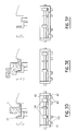
- FIG. 1 is a partial front sectional view of the device according to the invention fitted to a window treatment machine for window sashes;
- FIG. 2 is a sectional view along AA of the device according to the invention fitted to a window casement processing machine;
- FIGS. 3A to 3F are schematic views of operation of the device opposite the different types of amounts of leaf frames to identify.
- the figures illustrate the recognition device and the method for recognizing elements of different types, applied to the recognition of uprights of window sash frames or French windows.
- the device is therefore installed on a frame processing machine, for example a seal-laying machine, a fitting fittings or any other automatic machine for equipping or processing leaf frames.
- Figures 1 and 2 show more precisely the recognition device according to the invention.
- This device comprises a first stop 6 movable relative to the frame M of the machine, against which the upright is brought into contact 1.
- the leaf frame is brought into abutment on a fixed bank 45 which constitutes one of the organs of the device feeding or feeding frames on the machine.
- This stop 6 determines the reference angle of the frame and the clamping of the latter on the machine table is completed by holding elements placed for example on the other upright of the frame.
- the stop 6 is movable around an axis and provided with a counterweight 61 which returns it to its active projecting position automatically once the leaf frame has passed.
- the leaf frame is arranged on the machine table with its inner face placed on the table and its outer face facing up, referring to a leaf intended to be opened inwards.
- the upper crossmember 2 adjoins the bank 45.
- the recognition device also includes a probe 3 and a detector 4.
- the probe 3 is mounted mobile on the machine, by means of a translation device for example by rails or the like and is preferably driven by a preferably pneumatic device described below. Projecting from the plane of the machine table, a stop element 31 is therefore displaced to form a second contact on the other side of the upright 1. The thickness of this upright 1 is therefore determined by the distance separating the first stop 6 and the second movable stop 31.
- the detector 4 which is mounted near the probe 3 on the frame M of the machine comprises a movable part connected in displacement to the probe 3 and a fixed part secured to the frame of the machine.
- the constitution of the detector 4 is particularly visible in FIG. 2.
- the detector 4 is therefore mounted on a support piece 41 secured to the chassis M of the machine.
- the first horizontal axis 42 supports the assembly of at least one concealment member 50, this or these concealment members 50 being integral with the axis 42.
- the detector 4 also comprises an assembly of at least one sensor 60 fixedly mounted on the fixed part of the detector 4.
- the axis 42 supports the concealment members 50 and the axis 43 is the driving axis of the translation, on which the pneumatic energy acts, this axis being arranged in a valve valve system inside the detector. 4.
- the concealment member (s) 50 are displaced and positioned as a function of the displacement and of the positioning of the movable stop 31 and depending on the dimensions of the upright 1, obscure or not the light beam, magnetic or otherwise, of the sensor (s) 60 .
- the purpose of the device is to determine the type of leaf and its type of opening. In other words, it is a question of determining the type of the leaf and of locating if it is a right or left frame according to the type in order to control in the case of a joint laying machine l '' location for fitting the joint (on 4 or 3 sides), in the case of a fitting machine the location and the type of fitting to be fitted ...
- FIGS. 3A- to 3F represent in a schematic front view the first stop 6 and the second movable stop 31 of the probe 3, in transverse contact with an upright 1 of the leaf frame and in schematic view from above the detector 4 with the axis 42 with the concealing members 50 translated on the bearings 41 ′ and 41 "and the fixed sensors 60.
- FIG. 3A illustrates the maximum opening position of the probe 31 and the corresponding positions of the concealment members 50.
- FIG. 3B an upright with index cards is identified, the index cards being the elements of articulation of the leaf on the frame.
- the sensor C is obscured and the device according to the invention makes it possible to identify that it is a leaf with right opening for windows or French windows with one or two leaves, the frames being brought to the table of the processing machine in the position already specified.
- the sensors B and C are concealed and this arrangement determines, for a cremone upright, a leaf with left opening for windows or French windows with a single leaf.
- FIG. 3E represents the case where only the sensor D is concealed and determines for a casement amount the presence of a leaf opening to the left of a second leaf of a window or French window with double leaves.
- Figure 3F shows schematically the end position of the movable stop and therefore the absence of leaf on the machine table.
- the detector therefore comprises four inductive sensors 60 and three concealing members 50.
- six parameters can be determined corresponding to FIGS. 3A to 3F. It is obvious that by modifying the number of sensors and therefore the number of concealment members, it is possible to increase the different combinations obtained and therefore to adapt the device according to the invention to a lower or higher number of markings.
- inductive sensors 60 and occultation members 50 therefore makes it possible to obtain combinations where the presence or absence of the metallic elements which constitute the occultation members vis-à-vis with the sensors is defined. transmit this information in the form of pulses to the machine control automaton. It therefore suffices to modify the prerecorded parameters in order to adapt the method of recognition device to the identification of types of uprights of different dimensions.
- This embodiment is in no way limited by the fixed conditions for configuring the chassis, such as the arrangement of the interior face and of the upper cross member with respect to the machine.
Landscapes
- Physics & Mathematics (AREA)
- General Physics & Mathematics (AREA)
- Length Measuring Devices With Unspecified Measuring Means (AREA)
- Automatic Assembly (AREA)
- Wing Frames And Configurations (AREA)
- A Measuring Device Byusing Mechanical Method (AREA)
- Measurement Of The Respiration, Hearing Ability, Form, And Blood Characteristics Of Living Organisms (AREA)
Abstract
Le dispositif conforme à l'invention de reconnaissance d'éléments de types différents, chaque type ayant une dimension prédéterminée comprend une butée (6) contre laquelle est positionné un côté de l'élément (1), un palpeur (3) comprenant une butée mobile (31) destinée à venir en contact avec l'autre côté de l'élément (1) et un détecteur (4) constitué d'un ensemble d'au moins un organe d'occultation (50) solidaire du palpeur (3) et d'un ensemble d'au moins un capteur (60) fixe. De préférence le dispositif de reconnaissance est destiné à équiper une machine de travail de cadres de châssis de fenêtres ou porte-fenêtres afin de déterminer le type de châssis à traiter. <IMAGE>The device according to the invention for recognizing elements of different types, each type having a predetermined dimension comprises a stop (6) against which is positioned one side of the element (1), a feeler (3) comprising a stop mobile (31) intended to come into contact with the other side of the element (1) and a detector (4) consisting of an assembly of at least one concealing member (50) integral with the feeler (3) and of a set of at least one fixed sensor (60). Preferably the recognition device is intended to equip a working machine with window frame frames or French windows in order to determine the type of frame to be treated. <IMAGE>
Description
La présente invention concerne un procédé et un dispositif de reconnaissance d'éléments de dimension standardisée.The present invention relates to a method and a device for recognizing elements of standardized size.
Plus précisément, ce dispositif est destiné a équiper une machine de traitement de châssis de fenêtres ou de porte-fenêtres.More specifically, this device is intended to equip a processing machine for window frames or French windows.
Le problème dans de telles machines est de repérer quel type de châssis est amené à la machine afin de commander les caractéristiques d'équipement correspondantes, chaque type ayant des caractéristiques de dimension standard. La solution est donc de déterminer grâce à un dispositif simple et fiable la dimension adéquate de l'élément et de transmettre cette information, éventuellement modifiée par un paramètre préenregistré, au dispositif de commande de la machine.The problem in such machines is to identify which type of chassis is brought to the machine in order to control the corresponding equipment characteristics, each type having standard dimension characteristics. The solution is therefore to determine, using a simple and reliable device, the appropriate dimension of the element and to transmit this information, possibly modified by a prerecorded parameter, to the machine control device.
Ce dispositif plus particulièrement adapté à une machine d'équipement de châssis de fenêtres peut bien évidemment être utilisé dans toute application où il est nécessaire de repérer et reconnaître des éléments afin de les traiter en correspondance.This device more particularly adapted to a window frame equipment machine can obviously be used in any application where it is necessary to locate and recognize elements in order to treat them in correspondence.
L'invention propose un dispositif de reconnaissance comportant un palpeur et un détecteur correspondant, l'association de ces deux éléments permettant par déduction logique de déterminer le type de l'élément repéré, et en particulier dans le cas d'une machine d'équipement de châssis, le type de vantail et le sens d'ouverture. Il aurait été possible de réaliser un palpeur pour chacun des éléments à repérer, mais cela aurait conduit à multiplier et compliquer les paramétrages informatiques. Grâce à l'invention, les mêmes effets sont obtenus par un nombre de combinaisons limité.The invention proposes a recognition device comprising a feeler and a corresponding detector, the association of these two elements making it possible by logical deduction to determine the type of the element identified, and in particular in the case of an equipment machine. frame, type of leaf and opening direction. It would have been possible to carry out a probe for each of the elements to locate, but that would have led to multiply and complicate the computer settings. Thanks to the invention, the same effects are obtained by a limited number of combinations.
Pour ce faire la présente invention propose un procédé de reconnaissance d'éléments de type différent, chaque type ayant une dimension prédéterminée. Ce procédé est remarquable en ce qu'un ensemble d'au moins un organe d'occultation est déplacé et positionné en fonction de la dimension du type d'élément grâce à un dispositif de palpage, ce premier ensemble coopérant avec un ensemble d'au moins un capteur fixe, le ou les organes occultant selon plusieurs combinaisons le ou les capteurs, fournissant ainsi une information dépendante de la dimension repérée et spécifique au type d'élément présent.To do this, the present invention proposes a method for recognizing elements of different type, each type having a dimension predetermined. This method is remarkable in that a set of at least one concealing member is moved and positioned as a function of the dimension of the type of element by means of a feeler device, this first set cooperating with a set of at minus a fixed sensor, the organ (s) obscuring the sensor (s) in several combinations, thus providing information dependent on the dimension identified and specific to the type of element present.
Afin de réaliser l'agencement et les combinaisons les plus judicieuses possibles, le positionnement des organes d'occultation et des capteurs est défini en fonction du nombre et des dimensions des éléments à repérer.In order to achieve the most judicious possible arrangement and combinations, the positioning of the concealment members and of the sensors is defined according to the number and dimensions of the elements to be located.
Pour obtenir la commande souhaitée, l'information est modifiée par un paramètre préenregistré dépendant du type d'élément et de cette information modifiée résultent les paramètres de traitement de l'élément.To obtain the desired command, the information is modified by a prerecorded parameter depending on the type of element and from this modified information result the processing parameters of the element.
L'invention propose un dispositif de reconnaissance d'éléments de type différent, chaque type ayant une dimension prédéterminée ; ce dispositif comprend une butée contre laquelle est positionné un côté de l'élément, un palpeur mobile comprenant une butée mobile destinée à venir en contact avec l'autre côté de l'élément et un détecteur constitué d'un ensemble d'au moins un organe d'occultation solidaire du palpeur et d'un ensemble d'au moins un capteur fixe.The invention provides a device for recognizing elements of different types, each type having a predetermined dimension; this device comprises a stop against which is positioned one side of the element, a movable probe comprising a movable stop intended to come into contact with the other side of the element and a detector consisting of a set of at least one occultation member integral with the probe and a set of at least one fixed sensor.
Selon un mode de réalisation préféré, le détecteur comprend un axe supporté en translation par des paliers fixes, cet axe supportant solidairement le ou les organe(s) d'occultation et étant solidaire du palpeur.According to a preferred embodiment, the detector comprises an axis supported in translation by fixed bearings, this axis integrally supporting the occultation organ (s) and being integral with the probe.
De préférence le détecteur comprend un second axe parallèle au premier, supporté par les mêmes paliers et destiné à la rigidification du mécanisme de détection.Preferably the detector comprises a second axis parallel to the first, supported by the same bearings and intended for the stiffening of the detection mechanism.
L'application préférée de ce dispositif de reconnaissance est l'équipement d'une machine de travail de cadres de châssis de fenêtres ou porte-fenêtres, afin de déterminer le type de châssis à traiter ; selon cette application particulière, la butée est située à un angle de référence sur lequel est amené un côté du montant d'un cadre de battant grâce au dispositif d'amenage de la machine, le palpeur est commandé en translation par rapport au châssis fixe de la machine pour venir en contact avec l'autre côté du montant du cadre, le détecteur est supporté par une pièce de support solidaire du châssis de la machine.The preferred application of this recognition device is the equipment of a machine for working with window frame frames or French windows, in order to determine the type of frame to be treated; according to this particular application, the stop is located at a reference angle on which is brought one side of the upright of a leaf frame by means of the machine feed device, the probe is controlled in translation relative to the fixed frame of the machine to come into contact with the other side of the upright of the frame, the detector is supported by a support piece secured to the chassis of the machine.
L'invention est exposée ci-après plus en détail à l'aide de dessins représentant seulement un mode d'exécution.The invention is set out below in more detail with the aid of drawings representing only one embodiment.
- la figure 1 est une vue en coupe partielle et frontale du dispositif conforme à l'invention équipant une machine de traitement de châssis des battants de fenêtre ;- Figure 1 is a partial front sectional view of the device according to the invention fitted to a window treatment machine for window sashes;
- la figure 2 est une vue en coupe selon AA du dispositif conforme à l'invention équipant une machine de traitement de châssis de battants de fenêtre;- Figure 2 is a sectional view along AA of the device according to the invention fitted to a window casement processing machine;
- les figures 3A à 3F sont des vues schématiques de fonctionnement du dispositif en regard des différents types de montants de cadres de battants à repérer.- Figures 3A to 3F are schematic views of operation of the device opposite the different types of amounts of leaf frames to identify.
Les figures illustrent le dispositif de reconnaissance et le procédé de reconnaissance d'éléments de types différents, appliqués à la reconnaissance de montants de cadres de vantail de fenêtres ou porte-fenêtres. Le dispositif est donc mis en place sur une machine de traitement de cadres, par exemple une machine de pose de joint, une machine de pose de ferrures ou toute autre machine automatique d'équipement ou de traitement de cadres de vantail.The figures illustrate the recognition device and the method for recognizing elements of different types, applied to the recognition of uprights of window sash frames or French windows. The device is therefore installed on a frame processing machine, for example a seal-laying machine, a fitting fittings or any other automatic machine for equipping or processing leaf frames.
Les figures 1 et 2 représentent plus précisément le dispositif de reconnaissance conforme à l'invention.Figures 1 and 2 show more precisely the recognition device according to the invention.
Ce dispositif comporte une première butée 6 mobile par rapport au châssis M de la machine, contre laquelle est amené en contact le montant 1. De préférence le cadre de vantail est amené en butée sur une rive fixe 45 qui constitue un des organes du dispositif d'amenage ou d'alimentation des cadres sur la machine. Cette butée 6 détermine l'angle de référence du cadre et le bridage de celui-ci sur la table de la machine est complété par des éléments de maintien mis en place par exemple sur l'autre montant du cadre. La butée 6 est mobile autour d'un axe et pourvue d'une masselotte 61 qui la ramène dans sa position active saillante automatiquement une fois le cadre de vantail passé.This device comprises a
Selon le mode de réalisation représenté, comme on peut le voir sur ces figures 1 et 2 le cadre de vantail est disposé sur la table de la machine avec sa face intérieure posée sur la table et sa face extérieure dirigée vers le haut, en se référant à un vantail destiné à être ouvert vers l'intérieur. La traverse supérieure 2 jouxte, quant à elle, la rive 45.According to the embodiment shown, as can be seen in these Figures 1 and 2 the leaf frame is arranged on the machine table with its inner face placed on the table and its outer face facing up, referring to a leaf intended to be opened inwards. The
Le dispositif de reconnaissance comporte également un palpeur 3 et un détecteur 4.The recognition device also includes a
Le palpeur 3 est monté mobile sur la machine, grâce à un dispositif de translation par exemple par des rails ou équivalents et est de préférence entraîné par un dispositif de préférence pneumatique décrit ci-après. Faisant saillie du plan de la table de la machine, un élément de butée 31 est donc déplacé pour venir former un second contact de l'autre côté du montant 1. L'épaisseur de ce montant 1 est donc déterminée par la distance séparant la première butée 6 et la seconde butée mobile 31.The
Le détecteur 4 qui est monté à proximité du palpeur 3 sur le châssis M de la machine comporte une partie mobile reliée en déplacement au palpeur 3 et une partie fixe solidaire du châssis de la machine.The
Pour ce faire sont solidaires du palpeur 3 deux axes 42 et 43 qui coulissent en translation dans des paliers fixes 41' et 41" du détecteur. Ces arbres sont reliés en bout pour des raisons de rigidité par une plaquette ou équivalent 44.To do this, they are integral with the
La constitution du détecteur 4 est particulièrement visible sur la figure 2.The constitution of the
Le détecteur 4 est donc monté sur une pièce de support 41 solidaire du châssis M de la machine.The
Le premier axe horizontal 42 supporte l'ensemble d'au moins un organe d'occultation 50, ce ou ces organes d'occultation 50 étant solidaires de l'axe 42. Le détecteur 4 comporte par ailleurs un ensemble d'au moins un capteur 60 monté fixe sur la partie fixe du détecteur 4.The first
L'axe 42 supporte les organes d'occultation 50 et l'axe 43 est l'axe moteur de la translation, sur lequel agit l'énergie pneumatique, cet axe étant agencé en un système de soupape à tiroir à l'intérieur du détecteur 4.The
En conséquence le ou les organes d'occultation 50 sont déplacés et positionnés en fonction du déplacement et du positionnement de la butée mobile 31 et selon les dimensions du montant 1 viennent occulter ou non le faisceau lumineux, magnétique ou autre, du ou des capteurs 60.Consequently, the concealment member (s) 50 are displaced and positioned as a function of the displacement and of the positioning of the
Le fonctionnement du dispositif de reconnaissance appliqué au repérage de cadres de vantail va maintenant être décrit plus précisément grâce aux figures 3A à 3F.The operation of the recognition device applied to the identification of leaf frames will now be described more precisely using FIGS. 3A to 3F.
Le but du dispositif est de déterminer le type de vantail et son type d'ouverture. En d'autres termes, il s'agit de déterminer le type du vantail et de repérer s'il s'agit d'un cadre droit ou gauche selon le type afin de commander dans le cas d'une machine de pose de joint l'emplacement de mise en place du joint (sur 4 ou 3 côtés), dans le cas d'une machine de pose de ferrures l'emplacement et le type de ferrure à mettre en place...The purpose of the device is to determine the type of leaf and its type of opening. In other words, it is a question of determining the type of the leaf and of locating if it is a right or left frame according to the type in order to control in the case of a joint laying machine l '' location for fitting the joint (on 4 or 3 sides), in the case of a fitting machine the location and the type of fitting to be fitted ...
Pour illustrer ce fonctionnement, les figures 3A- à 3F représentent en vue schématique frontale la première butée 6 et la seconde butée mobile 31 du palpeur 3, en contact transversal avec un montant 1 de cadre de vantail et en vue schématique de dessus le détecteur 4 avec l'axe 42 avec les organes d'occultation 50 translatés sur les paliers 41' et 41" et les capteurs fixes 60.To illustrate this operation, FIGS. 3A- to 3F represent in a schematic front view the
La figure 3A illustre le positionnement d'ouverture maximum du palpeur 31 et les positions correspondantes des organes d'occultation 50.FIG. 3A illustrates the maximum opening position of the
Dans le cas de la figure 3B est repéré un montant à fiches, les fiches étant les éléments d'articulation du vantail sur le dormant. Dans ce cas de figure, seul le capteur C est occulté et le dispositif conforme à l'invention permet de repérer qu'il s'agit d'un vantail à ouverture à droite pour fenêtres ou porte-fenêtres à un ou deux vantaux, les cadres étant amenés sur la table de la machine de traitement dans la position déjà précisée.In the case of FIG. 3B, an upright with index cards is identified, the index cards being the elements of articulation of the leaf on the frame. In this case, only the sensor C is obscured and the device according to the invention makes it possible to identify that it is a leaf with right opening for windows or French windows with one or two leaves, the frames being brought to the table of the processing machine in the position already specified.
Selon la figure 3C, les capteurs B et C sont occultés et cette disposition détermine pour un montant à crémone, un vantail à ouverture à gauche pour fenêtres ou porte-fenêtres à vantail unique.According to FIG. 3C, the sensors B and C are concealed and this arrangement determines, for a cremone upright, a leaf with left opening for windows or French windows with a single leaf.
Selon la figure 3D seul le capteur B est occulté et, pour un montant d'un abattant, sa disposition détermine la présence d'un vantail basculant et permet de déterminer la traverse à équiper.According to FIG. 3D, only the sensor B is concealed and, for the amount of a flap, its arrangement determines the presence of a leaf. tilting and determines the crosspiece to be fitted.
La figure 3E représente le cas où seul le capteur D est occulté et détermine pour un montant à battement la présence d'un vantail à ouverture à gauche d'un second vantail d'une fenêtre ou porte-fenêtre à double vantaux.FIG. 3E represents the case where only the sensor D is concealed and determines for a casement amount the presence of a leaf opening to the left of a second leaf of a window or French window with double leaves.
La figure 3F schématise la position de fin de course de la butée mobile et donc l'absence de vantail sur la table de la machine.Figure 3F shows schematically the end position of the movable stop and therefore the absence of leaf on the machine table.
Selon l'agencement représenté, le détecteur comporte donc quatre capteurs inductifs 60 et trois organes d'occultation 50. Ainsi sont déterminables six paramètres correspondant aux figures 3A à 3F. Il est bien évident qu'en modifiant le nombre de capteurs et donc le nombre d'organes d'occultation l'on peut augmenter les différentes combinaisons obtenues et donc adapter le dispositif conforme à l'invention à un nombre inférieur ou supérieur de repérages.According to the arrangement shown, the detector therefore comprises four
L'association de capteurs inductifs 60 et d'organes d'occultation 50 permet donc d'obtenir des combinaisons où est définie la présence ou non des éléments métalliques que constituent les organes d'occultation en vis-à-vis avec les capteurs et de transmettre ces informations sous forme d'impulsions à l'automate de commande de la machine. Il suffit donc de modifier les paramètres préenregistrés pour adapter le procédé de dispositif de reconnaissance au repérage de type de montants de dimensions différentes.The association of
Ce mode d'exécution n'est nullement limité par les conditions fixes de paramétrage du châssis telles que l'agencement de la face intérieure et de la traverse supérieure par rapport à la machine.This embodiment is in no way limited by the fixed conditions for configuring the chassis, such as the arrangement of the interior face and of the upper cross member with respect to the machine.
Claims (7)
Applications Claiming Priority (2)
| Application Number | Priority Date | Filing Date | Title |
|---|---|---|---|
| FR8916415A FR2655724B1 (en) | 1989-12-12 | 1989-12-12 | METHOD AND DEVICE FOR RECOGNIZING DIFFERENT ELEMENTS OF STANDARDIZED DIMENSION, ESPECIALLY FRAMES OF WINDOW FRAMES DURING MANUFACTURE. |
| FR8916415 | 1989-12-12 |
Publications (2)
| Publication Number | Publication Date |
|---|---|
| EP0446544A2 true EP0446544A2 (en) | 1991-09-18 |
| EP0446544A3 EP0446544A3 (en) | 1991-09-25 |
Family
ID=9388419
Family Applications (1)
| Application Number | Title | Priority Date | Filing Date |
|---|---|---|---|
| EP19900403482 Withdrawn EP0446544A3 (en) | 1989-12-12 | 1990-12-06 | Method and apparatus for recognition of several elements of standard dimensions, particularly for window frames during manufacture |
Country Status (7)
| Country | Link |
|---|---|
| US (1) | US5121559A (en) |
| EP (1) | EP0446544A3 (en) |
| JP (1) | JPH04110605A (en) |
| CA (1) | CA2031999A1 (en) |
| FI (1) | FI905792A7 (en) |
| FR (1) | FR2655724B1 (en) |
| NO (1) | NO905349L (en) |
Families Citing this family (1)
| Publication number | Priority date | Publication date | Assignee | Title |
|---|---|---|---|---|
| US6116272A (en) * | 1999-03-26 | 2000-09-12 | Daimlerchrysler Coroporation | Debris resistant oil pressure relief valve |
Family Cites Families (5)
| Publication number | Priority date | Publication date | Assignee | Title |
|---|---|---|---|---|
| US2244964A (en) * | 1939-10-21 | 1941-06-10 | Sheffield Corp | Measuring instrument |
| CH479853A (en) * | 1968-07-15 | 1969-10-15 | Meier Johann | Device for measuring lengths |
| FR2298081A1 (en) * | 1975-01-15 | 1976-08-13 | Poclain Sa | TWO-PIECE RELATIVE POSITION DETECTOR |
| DE3039483C2 (en) * | 1980-10-18 | 1986-09-11 | Dr. Johannes Heidenhain Gmbh, 8225 Traunreut | Incremental length or angle measuring device |
| US4700485A (en) * | 1986-03-10 | 1987-10-20 | Teleflex Incorporated | Linear measuring device |
-
1989
- 1989-12-12 FR FR8916415A patent/FR2655724B1/en not_active Expired - Fee Related
-
1990
- 1990-11-23 FI FI905792A patent/FI905792A7/en not_active Application Discontinuation
- 1990-12-06 EP EP19900403482 patent/EP0446544A3/en not_active Withdrawn
- 1990-12-11 NO NO90905349A patent/NO905349L/en unknown
- 1990-12-11 CA CA002031999A patent/CA2031999A1/en not_active Abandoned
- 1990-12-11 US US07/625,443 patent/US5121559A/en not_active Expired - Fee Related
- 1990-12-12 JP JP2410470A patent/JPH04110605A/en active Pending
Also Published As
| Publication number | Publication date |
|---|---|
| CA2031999A1 (en) | 1991-06-13 |
| EP0446544A3 (en) | 1991-09-25 |
| FR2655724A1 (en) | 1991-06-14 |
| US5121559A (en) | 1992-06-16 |
| FI905792A0 (en) | 1990-11-23 |
| NO905349D0 (en) | 1990-12-11 |
| NO905349L (en) | 1991-06-13 |
| FI905792A7 (en) | 1991-06-13 |
| JPH04110605A (en) | 1992-04-13 |
| FR2655724B1 (en) | 1993-11-19 |
Similar Documents
| Publication | Publication Date | Title |
|---|---|---|
| EP0141717B1 (en) | Positioning device for robots | |
| FR2631877A1 (en) | SUCTION FAIRING FOR A CUTTING MACHINE OF A SHEET MATERIAL WITH A ROTARY TOOL, AND ASSEMBLY COMPRISING SUCH A FAIRING | |
| CA1268976A (en) | Method and installation for machining a hollow part through milling along a predetermined marking | |
| EP0446544A2 (en) | Method and apparatus for recognition of several elements of standard dimensions, particularly for window frames during manufacture | |
| EP3662454B2 (en) | Assembly of automatic gates comprising substantially identical motor assemblies and method for producing such an assembly | |
| DE69839380T2 (en) | Loading device for lathes | |
| EP0242309B1 (en) | Bending press with pivoting beam | |
| EP1010126B1 (en) | Method and device for reading raised designs borne by a transparent or translucent container | |
| DE69304501T2 (en) | Process for checking the adaptation of a lens to be ground to an eyeglass frame on a grinding machine | |
| EP1413394B1 (en) | Door for automated machine | |
| FR2668185A1 (en) | Passage with controlled access authorisation fitted with a closure device using a swing leaf with vertical axis | |
| FR2485617A1 (en) | APPARATUS FOR MANEUVERING THE ARM OF A DRUM MINE MACHINE, AND MACHINE EQUIPPED WITH SUCH A DEVICE | |
| EP0087342A1 (en) | Alignment appliance for accosting and welding sheet ends | |
| EP0517552A1 (en) | Machine for mounting iron fittings on profiles, especially for mounting latch plates on profiles destined to form window- or doorframes after subsequent assembling | |
| FR2758522A1 (en) | DOOR SYSTEM, PARTICULARLY FOR A PASSENGER AIRCRAFT | |
| JPH11129098A (en) | Metal sheet panel manufacturing machine | |
| NL8006390A (en) | CASSETTE FOR MAGNETIC TAPE. | |
| FR2540224A1 (en) | Laser-beam protection device for machine tools of the bending press type | |
| FR2595403A1 (en) | Device for projecting a roller shutter and shutter fitted with this device | |
| EP0432078A2 (en) | Lens bevelling machine | |
| CN210343098U (en) | Anti-theft goods taking door of vending machine | |
| EP1597103B1 (en) | Retractable roof for a vehicle | |
| FR2765547A1 (en) | Procedure for fitting of door mount to body on motor vehicle production line | |
| FR2483269A1 (en) | Reel unwinding starter and guide - has starting head passing under reel end actuated by hydraulic jack mounted on frame | |
| FR2848499A1 (en) | Marking system using laser beam operates within light proof dual chamber casing offering protection against stray reflected light |
Legal Events
| Date | Code | Title | Description |
|---|---|---|---|
| PUAI | Public reference made under article 153(3) epc to a published international application that has entered the european phase |
Free format text: ORIGINAL CODE: 0009012 |
|
| PUAL | Search report despatched |
Free format text: ORIGINAL CODE: 0009013 |
|
| AK | Designated contracting states |
Kind code of ref document: A2 Designated state(s): AT BE CH DE DK ES GB GR IT LI LU NL SE |
|
| AK | Designated contracting states |
Kind code of ref document: A3 Designated state(s): AT BE CH DE DK ES GB GR IT LI LU NL SE |
|
| 17P | Request for examination filed |
Effective date: 19911217 |
|
| STAA | Information on the status of an ep patent application or granted ep patent |
Free format text: STATUS: THE APPLICATION IS DEEMED TO BE WITHDRAWN |
|
| 18D | Application deemed to be withdrawn |
Effective date: 19930701 |