EP0446436A2 - Process and device for burning impurities in a media flow - Google Patents
Process and device for burning impurities in a media flow Download PDFInfo
- Publication number
- EP0446436A2 EP0446436A2 EP90123053A EP90123053A EP0446436A2 EP 0446436 A2 EP0446436 A2 EP 0446436A2 EP 90123053 A EP90123053 A EP 90123053A EP 90123053 A EP90123053 A EP 90123053A EP 0446436 A2 EP0446436 A2 EP 0446436A2
- Authority
- EP
- European Patent Office
- Prior art keywords
- flue gas
- mixing tube
- gas mixing
- heat exchanger
- media stream
- Prior art date
- Legal status (The legal status is an assumption and is not a legal conclusion. Google has not performed a legal analysis and makes no representation as to the accuracy of the status listed.)
- Granted
Links
Images


Classifications
-
- F—MECHANICAL ENGINEERING; LIGHTING; HEATING; WEAPONS; BLASTING
- F23—COMBUSTION APPARATUS; COMBUSTION PROCESSES
- F23G—CREMATION FURNACES; CONSUMING WASTE PRODUCTS BY COMBUSTION
- F23G7/00—Incinerators or other apparatus for consuming industrial waste, e.g. chemicals
- F23G7/06—Incinerators or other apparatus for consuming industrial waste, e.g. chemicals of waste gases or noxious gases, e.g. exhaust gases
- F23G7/061—Incinerators or other apparatus for consuming industrial waste, e.g. chemicals of waste gases or noxious gases, e.g. exhaust gases with supplementary heating
- F23G7/065—Incinerators or other apparatus for consuming industrial waste, e.g. chemicals of waste gases or noxious gases, e.g. exhaust gases with supplementary heating using gaseous or liquid fuel
- F23G7/066—Incinerators or other apparatus for consuming industrial waste, e.g. chemicals of waste gases or noxious gases, e.g. exhaust gases with supplementary heating using gaseous or liquid fuel preheating the waste gas by the heat of the combustion, e.g. recuperation type incinerator
Definitions
- the invention relates to a method for burning contaminants contained in a media stream, the media stream with the contaminants being passed through heat exchanger tubes and passed through a combustion chamber in the heated state. From there, the media flow is discharged through a flue gas mixing tube and then through a main combustion chamber concentrically surrounding the flue gas mixing tube and finally, freed from the contaminants, via the heat exchanger tubes.
- the invention also relates to a device for burning contaminants contained in a media stream, consisting of a cylindrical container with an inlet connector and an outlet connector for the media stream. This is first introduced through an internally cylindrical bundle of axially extending bundles of heat exchanger tubes into an annular chamber which surrounds a burner arranged on one end of the container and passes into a flue gas mixing tube arranged concentrically with the container. This in turn is connected to a main combustion chamber, from which the media flow can be fed to the outlet connection via the heat exchanger tubes.
- the proportion of oxidizable constituents in the media stream must be limited to a certain extent so that the combustion chamber temperature can be kept at its desired level even with a minimum burner output.
- a combustion method is known from DE-OS 36 05 415, wherein the exhaust gas and fresh air that have already been cleaned are at least partially mixed with the media stream to be supplied to the combustion device to the desired extent.
- the cleaned exhaust gas to be mixed is discharged either after flowing around a heat exchanger or directly from the burner chamber and has to be fed back into the device via a special line system. This is to prevent control mechanisms, such as flaps or valves, which work precisely in the event of pressure fluctuations and which must have a relatively good seal, are exposed to high temperatures. To carry out the known method, a relatively large expenditure on the device is therefore inevitable.
- the invention is based on the object of proposing a method of the type described at the outset which makes it unnecessary to keep the temperature constant in the event of fluctuating amounts of oxidizable constituents in the media stream Introduce the media flow into the combustion device by admixing to lower the concentration of the oxidizable constituents.
- the combustion chamber temperature can surprisingly nevertheless be kept very effectively at a constant level.
- the media mixture flows around the full length of the flue gas mixing tube as it passes through the main combustion chamber, thereby influencing the combustion chamber temperature. This is also influenced by the temperature of the media flow flowing from the heat exchanger tubes to the burner. Since the heat exchanger tubes are also flushed by a media stream which is reduced as a function of the admixing volume, the temperature of the media stream flowing to the burner can also be influenced, depending on the temperature thereof, without a media stream mixture itself having to be supplied to the burner beforehand.
- a device as described above is suitable for carrying out this method, in which, according to the invention, a controllable bypass is connected to a prechamber provided with the inlet connector, from which the heat exchanger tubes are fed, and which opens concentrically in the outlet region of the flue gas mixing tube.
- the inflow cross section of the bypass can be controlled in a simple manner by means of a flap which is mounted within the prechamber and is therefore not exposed to high temperatures, especially since the volume flow to be mixed has a relatively low temperature which acts on the flap area.
- the bypass is provided with a connecting piece which projects into the flue gas mixing tube, has radial openings and is sealed at the end.
- the device consists essentially of a cylindrical container 1, which is provided on the outside with a heat and sound insulation 2.
- the container 1 is provided in the vicinity of an end face 3 with an inlet connection 4 which penetrates radially through the container wall and is connected to the suction side of a radial blower 5 arranged concentrically on the end face.
- An impeller 6 of the radial fan 5 is surrounded by a housing 7 which is provided with an annular gap 8. This opens into a prechamber 9, which is connected both to the inlet side of heat exchanger tubes 10, which are arranged cylindrically near the jacket of the container 1, and to the inlet side of a coxial bypass 11.
- the heat exchanger tubes 10 extend axially over the most essential part of the length of the container 1 and open into an annular chamber 12 which adjoins an end face 13 of the container 1.
- the annular chamber 12 encloses a burner 14, which is arranged concentrically on the end face 13 and opens into a coaxial flue gas mixing tube 15.
- the outlet cross section of the flue gas mixing tube 15 lies at an axial distance from one that separates the antechamber 9 from the rest of the container 1 End wall 16. This is assigned a cylinder 17, which extends over the most essential part of the length of the flue gas mixing tube 15 and defines with it a main combustion chamber 18 which is connected in the vicinity of the inlet cross section of the flue gas mixing tube 15 to an annular space 19 which connects the heat exchanger tubes 10 contains. An outlet connection 20 is connected to the annular space 19, adjacent to the inlet connection 4.
- the bypass 11 is equipped with a flap 21, with which the media flow conveyed via the radial fan 5 into the prechamber 9 is, to a greater or lesser extent, via the bypass 11 bypassing the heat exchanger tubes 10, the annular chamber 12 and the burner 14 Leaving from the flue gas mixing tube 15 and so far already pre-treated media stream can be admixed.
- the bypass 11 consists of a nozzle 22 which is provided with radial openings 23 and is closed on the end face.
- the container 1 can also be arranged vertically instead of in the horizontal position shown in FIG. 1, with either the radial fan 5 on the bottom side and the burner 14 on the ceiling side (FIG. 2) or the radial fan 5 on the ceiling side and the burner 14 are arranged on the bottom (FIG. 3).
- the inlet connector 4 and the outlet connector 20 are provided on opposite sides of the container 1.
Landscapes
- Engineering & Computer Science (AREA)
- Environmental & Geological Engineering (AREA)
- Mechanical Engineering (AREA)
- General Engineering & Computer Science (AREA)
- Incineration Of Waste (AREA)
- Gas Burners (AREA)
- Portable Nailing Machines And Staplers (AREA)
- Gasification And Melting Of Waste (AREA)
Abstract
Bei schwankenden Mengen oxidierbarer Bestandteile in einem Medienstrom, der durch Verbrennung dieser Bestandteile gereinigt werden soll, wird durch Zumischung die Konzentration der oxidierbaren Bestandteile abgesenkt. Um eine Zumischung vor Einleitung des Medienstroms in die Verbrennungsvorrichtung entbehrlich zu machen und gleichwohl die Brennkammertemperatur auf ihrem Sollniveau zu halten, wird vorgeschlagen, einen variablen Anteil des Störstoffe enthaltenden Medienstroms und/oder einen Anteil Frischluft dem aus einem Rauchgasmischrohr (15) austretenden Medienstrom zuzumischen. Das Rauchgasmischrohr (15) ist einem Brenner (14) in Strömungsrichtung nachgeordnet, so daß die Zumischung erfolgt, nachdem der Medienstrom den Brenner (14) bereits passiert hat.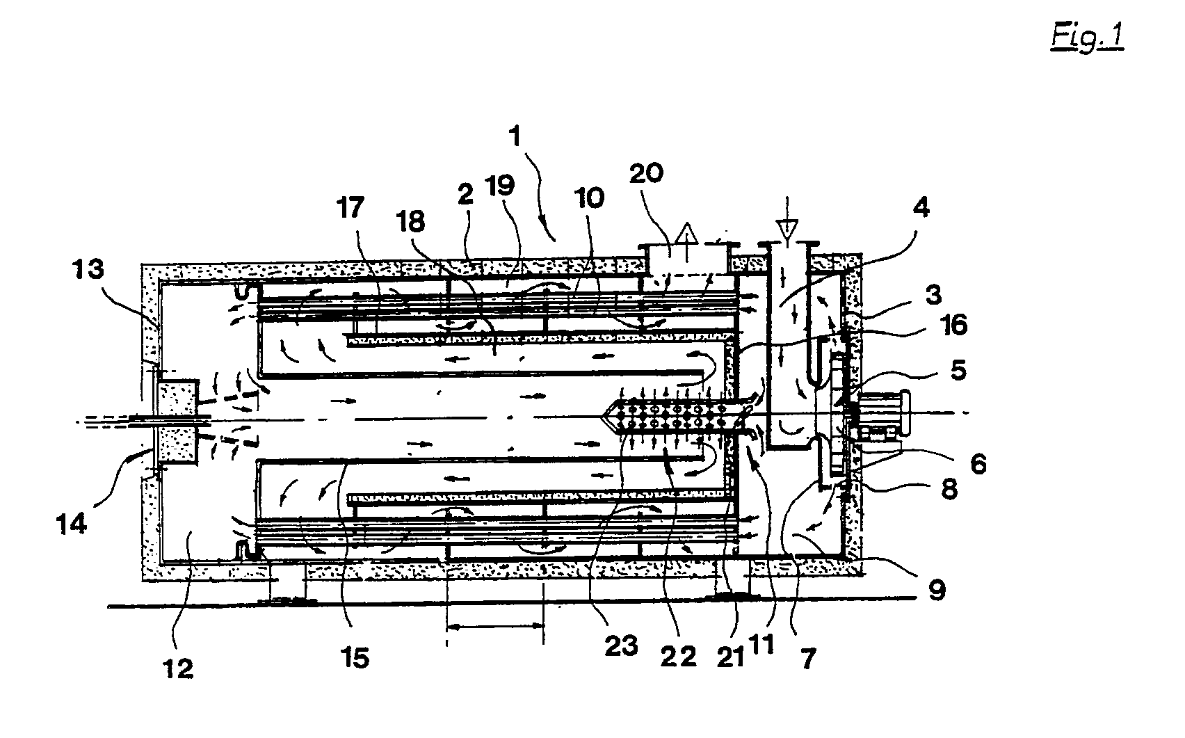
Description
Die Erfindung betrifft ein Verfahren zum Verbrennen von in einem Medienstrom enthaltenen Störstoffen, wobei der Medienstrom mit den Störstoffen durch Wärmetauscherrohre hindurchgeleitet und in aufgeheiztem Zustand durch eine Brennkammer geführt wird. Von dort aus wird der Medienstrom durch ein Rauchgasmischrohr und anschließend durch eine das Rauchgasmischrohr konzentrisch umgebende Hauptbrennkammer und schließlich, von den Störstoffen befreit, über die Wärmetauscherrohre abgeleitet.The invention relates to a method for burning contaminants contained in a media stream, the media stream with the contaminants being passed through heat exchanger tubes and passed through a combustion chamber in the heated state. From there, the media flow is discharged through a flue gas mixing tube and then through a main combustion chamber concentrically surrounding the flue gas mixing tube and finally, freed from the contaminants, via the heat exchanger tubes.
Die Erfindung betrifft auch eine Vorrichtung zum Verbrennen von in einem Medienstrom enthaltenen Störstoffen, bestehend aus einem zylindrischen Behälter mit einem Eintrittsstutzen und einem Austrittsstutzen für den Medienstrom. Dieser wird zunächst durch im Innern des Behälters zylinderförmig angeordnete und sich axial erstreckende Bündel aus Wärmetauscherrohren in eine Ringkammer eingeleitet, die einen an einer Stirnseite des Behälters angeordneten Brenner umschließt und in ein konzentrisch zum Behälter angeordnetes Rauchgasmischrohr übergeht. Dieses ist wiederum mit einer Hauptbrennkammer verbunden, von der aus der Medienstrom über die Wärmetauscherrohre dem Austrittsstutzen zuleitbar ist.The invention also relates to a device for burning contaminants contained in a media stream, consisting of a cylindrical container with an inlet connector and an outlet connector for the media stream. This is first introduced through an internally cylindrical bundle of axially extending bundles of heat exchanger tubes into an annular chamber which surrounds a burner arranged on one end of the container and passes into a flue gas mixing tube arranged concentrically with the container. This in turn is connected to a main combustion chamber, from which the media flow can be fed to the outlet connection via the heat exchanger tubes.
Da die Brennkammertemperatur bestimmte Werte nicht überschreiten darf, muß die anteilige Menge oxidierbarer Bestandteile im Medienstrom auf ein bestimmtes Ausmaß begrenzt werden, damit auch bei minimaler Brennerleistung die Brennkammertemperatur auf ihrem Sollniveau gehalten werden kann.Since the combustion chamber temperature must not exceed certain values, the proportion of oxidizable constituents in the media stream must be limited to a certain extent so that the combustion chamber temperature can be kept at its desired level even with a minimum burner output.
Um dennoch einen Medienstrom mit größeren Mengen an oxidierbaren Bestandteilen behandeln zu können, ist aus der DE-OS 36 05 415 ein Verbrennungsverfahren bekannt, wobei dem der Verbrennungsvorrichtung zuzuführenden Medienstrom im gewünschten Umfang zumindest teilweise innerhalb der Vorrichtung bereits gereinigtes Abgas und auch Frischluft beigemischt wird. Das beizumischende gereinigte Abgas wird entweder nach Umströmung eines Wärmetauschers oder unmittelbar aus dem Brennerraum abgeführt und muß über ein besonderes Leitungssystem der Vorrichtung wieder zugeführt werden. Dadurch soll vermieden werden, daß Steuermechanismen, wie Klappen oder Ventile, die bei Druckschwankungen exakt arbeiten und über eine relativ gute Dichtigkeit verfügen müssen, hohen Temperaturen ausgesetzt sind. Zur Durchführung des bekannten Verfahrens ist daher ein verhältnismäßig großer Vorrichtungsaufwand unvermeidlich.In order to be able to treat a media stream with larger amounts of oxidizable constituents, a combustion method is known from DE-OS 36 05 415, wherein the exhaust gas and fresh air that have already been cleaned are at least partially mixed with the media stream to be supplied to the combustion device to the desired extent. The cleaned exhaust gas to be mixed is discharged either after flowing around a heat exchanger or directly from the burner chamber and has to be fed back into the device via a special line system. This is to prevent control mechanisms, such as flaps or valves, which work precisely in the event of pressure fluctuations and which must have a relatively good seal, are exposed to high temperatures. To carry out the known method, a relatively large expenditure on the device is therefore inevitable.
Der Erfindung liegt die Aufgabe zugrunde, ein Verfahren der eingangs beschriebenen Art vorzuschlagen, das es zur Konstanthaltung der Temperatur bei schwankenden Mengen oxidierbarer Bestandteile im Medienstrom entbehrlich macht, vor Einleitung des Medienstroms in die Verbrennungsvorrichtung durch Zumischung die Konzentration der oxidierbaren Bestandteile abzusenken.The invention is based on the object of proposing a method of the type described at the outset which makes it unnecessary to keep the temperature constant in the event of fluctuating amounts of oxidizable constituents in the media stream Introduce the media flow into the combustion device by admixing to lower the concentration of the oxidizable constituents.
Zur Lösung dieser Aufgabe wird von einem Verfahren der im Oberbegriff des Anspruchs 1 genannten gattungsgemäßen Art ausgegangen, welches erfindungsgemäß die im kennzeichnenden Teil desselben angegebenen Merkmale aufweist.To achieve this object, a method of the generic type mentioned in the preamble of
Durch die erfindungsgemäße Zumischung in einem Bereich, in dem der Haupt-Medienstrom bereits den Brenner und den wesentlichsten Teil des daran angeschlossenen Rauchgasmischrohrs passiert hat, läßt sich überraschenderweise gleichwohl die Brennkammertemperatur sehr wirksam auf einem konstanten Niveau halten. Das Mediengemisch umströmt nämlich bei seiner Passage durch die Hauptbrennkammer das Rauchgasmischrohr über dessen volle Länge und beeinflußt dadurch die Brennkammertemperatur. Diese wird zudem durch die Temperatur des aus den Wärmetauscherrohren dem Brenner zuströmenden Medienstroms beeinflußt. Da auch die Wärmetauscherrohre vom von einem in Abhängigkeit vom Zumischvolumen reduzierten Medienstrom durchspült werden, ist somit - abhängig auch von dessen Temperatur - auch die Temperatur des dem Brenner zuströmenden Medienstroms beeinflußbar, ohne daß diesem selbst zuvor ein Medienstromgemisch zugeleitet werden muß.Through the admixture according to the invention in a region in which the main media stream has already passed the burner and the most essential part of the flue gas mixing tube connected to it, the combustion chamber temperature can surprisingly nevertheless be kept very effectively at a constant level. The media mixture flows around the full length of the flue gas mixing tube as it passes through the main combustion chamber, thereby influencing the combustion chamber temperature. This is also influenced by the temperature of the media flow flowing from the heat exchanger tubes to the burner. Since the heat exchanger tubes are also flushed by a media stream which is reduced as a function of the admixing volume, the temperature of the media stream flowing to the burner can also be influenced, depending on the temperature thereof, without a media stream mixture itself having to be supplied to the burner beforehand.
Zur Durchführung dieses Verfahrens bietet sich eine oben beschriebene Vorrichtung an, bei der erfindungsgemäß an eine mit dem Eintrittsstutzen versehene Vorkammer, aus der die Wärmetauscherrohre gespeist werden, ein regulierbarer Bypass angeschlossen ist, der konzentrisch im Auslaßbereich des Rauchgasmischrohrs mündet.A device as described above is suitable for carrying out this method, in which, according to the invention, a controllable bypass is connected to a prechamber provided with the inlet connector, from which the heat exchanger tubes are fed, and which opens concentrically in the outlet region of the flue gas mixing tube.
Der Einströmquerschnitt des Bypasses läßt sich in einfacher Weise durch eine Klappe steuern, die innerhalb der Vorkammer gelagert ist und schon deshalb keinen hohen Temperaturen ausgesetzt wird, zumal der zuzumischende Volumenstrom verhältnismäßig niedriger Temperatur den Klappenbereich beaufschlagt.The inflow cross section of the bypass can be controlled in a simple manner by means of a flap which is mounted within the prechamber and is therefore not exposed to high temperatures, especially since the volume flow to be mixed has a relatively low temperature which acts on the flap area.
Nach einer Ausgestaltung der Erfindung ist der Bypass mit einem in das Rauchgasmischrohr hineinragenden, radiale Durchbrüche aufweisenden und stirnseitig verschlossenen Stutzen versehen.According to one embodiment of the invention, the bypass is provided with a connecting piece which projects into the flue gas mixing tube, has radial openings and is sealed at the end.
Durch diese Ausgestaltung kann dem aus dem Rauchgasmischrohr austretenden Medienstrom ein Anteil des noch mit Störstoffen behafteten Medienstroms oder aber auch Frischluft intensiv induziert werden.With this configuration, a portion of the media stream still contaminated with contaminants or else fresh air can be intensively induced in the media stream emerging from the flue gas mixing tube.
In der Zeichnung ist ein Ausführungsbeispiel einer Vorrichtung zur Durchführung des erfindungsgemäßen Verfahrens dargestellt. Es zeigen:
- Fig. 1
- einen Längsschnitt durch die Vorrichtung;
- Fig. 2 und 3
- je eine mit ihrer Mittelachse vertikal angeordnete Vorrichtung.
- Fig. 1
- a longitudinal section through the device;
- 2 and 3
- one device vertically arranged with its central axis.
Die Vorrichtung besteht im wesentlichen aus einem zylindrischen Behälter 1, der außenseitig mit einer wärme- und schalldämmenden Isolierung 2 versehen ist.The device consists essentially of a
Der Behälter 1 ist in der Nähe einer Stirnseite 3 mit einem die Behälterwandung radial durchdringenden Eintrittsstutzen 4 versehen, der an die Saugseite eines konzentrisch auf der Stirnseite angeordneten Radialgebläses 5 angeschlossen ist. Ein Laufrad 6 des Radialgebläses 5 ist von einem Gehäuse 7 umgeben, das mit einem Ringspalt 8 versehen ist. Dieser mündet in eine Vorkammer 9, die sowohl mit der Eintrittsseite von in Mantelnähe des Behälters 1 zylinderförmig angeordneten Wärmetauscherrohren 10 wie auch mit der Eintrittsseite eines koxialen Bypasses 11 in Verbindung steht.The
Die Wärmetauscherrohre 10 erstrecken sich axial über den wesentlichsten Teil der Länge des Behälters 1 und münden in eine Ringkammer 12, die an eine Stirnseite 13 des Behälters 1 angrenzt. Die Ringkammer 12 umschließt einen Brenner 14, der konzentrisch auf der Stirnseite 13 angeordnet ist und in ein koaxiales Rauchgasmischrohr 15 mündet.The
Der Austrittsquerschnitt des Rauchgasmischrohrs 15 liegt in einem axialen Abstand zu einer die Vorkammer 9 vom übrigen Teil des Behälters 1 abtrennenden Stirnwand 16. Dieser ist ein Zylinder 17 zugeordnet, der sich über den wesentlichsten Teil der Länge des Rauchgasmischrohrs 15 erstreckt und mit diesem eine Hauptbrennkammer 18 definiert, die in der Nähe des Eintrittsquerschnitts des Rauchgasmischrohrs 15 mit einem Ringraum 19 verbunden ist, welcher die Wärmetauscherrohre 10 enthält. Am Ringraum 19 ist, dem Eintrittsstutzen 4 benachbart, ein Austrittsstutzen 20 angeschlossen.The outlet cross section of the flue
Der Bypass 11 ist mit einer Klappe 21 ausgerüstet, mit der sich der über das Radialgebläse 5 in die Vorkammer 9 geförderte Medienstrom zu einem mehr oder weniger großen Teil über den Bypass 11 unter Umgehung der Wärmetauscherrohre 10, der Ringkammer 12 und des Brenners 14 unmittelbar dem aus dem Rauchgasmischrohr 15 austretenden und insoweit bereits vorbehandelten Medienstrom beimischen läßt. Dazu besteht der Bypass 11 aus einem Stutzen 22, der mit radialen Durchbrüchen 23 versehen und stirnseitig verschlossen ist.The bypass 11 is equipped with a flap 21, with which the media flow conveyed via the
Wie die Fig. 2 und 3 zeigen, läßt sich der Behälter 1 statt in der in Fig. 1 dargestellten horizontalen Position auch vertikal anordnen, wobei entweder das Radialgebläse 5 bodenseitig und der Brenner 14 deckenseitig (Fig. 2) oder das Radialgebläse 5 deckenseitig und der Brenner 14 bodenseitig (Fig. 3) angeordnet sind. Der Eintrittsstutzen 4 und der Austrittsstutzen 20 sind dabei auf gegenüberliegenden Seiten des Behälters 1 vorgesehen.As shown in FIGS. 2 and 3, the
Claims (3)
Priority Applications (1)
| Application Number | Priority Date | Filing Date | Title |
|---|---|---|---|
| AT90123053T ATE86028T1 (en) | 1990-03-10 | 1990-12-01 | METHOD AND DEVICE FOR BURNING CONTAMINANT SUBSTANCES CONTAINED IN A MEDIA STREAM. |
Applications Claiming Priority (2)
| Application Number | Priority Date | Filing Date | Title |
|---|---|---|---|
| DE4007624 | 1990-03-10 | ||
| DE4007624 | 1990-03-10 |
Publications (3)
| Publication Number | Publication Date |
|---|---|
| EP0446436A2 true EP0446436A2 (en) | 1991-09-18 |
| EP0446436A3 EP0446436A3 (en) | 1992-02-26 |
| EP0446436B1 EP0446436B1 (en) | 1993-02-24 |
Family
ID=6401877
Family Applications (1)
| Application Number | Title | Priority Date | Filing Date |
|---|---|---|---|
| EP90123053A Expired - Lifetime EP0446436B1 (en) | 1990-03-10 | 1990-12-01 | Process and device for burning impurities in a media flow |
Country Status (5)
| Country | Link |
|---|---|
| US (1) | US5161966A (en) |
| EP (1) | EP0446436B1 (en) |
| AT (1) | ATE86028T1 (en) |
| CA (1) | CA2037866A1 (en) |
| DE (1) | DE59000936D1 (en) |
Families Citing this family (11)
| Publication number | Priority date | Publication date | Assignee | Title |
|---|---|---|---|---|
| IT1248599B (en) * | 1991-05-10 | 1995-01-19 | Bono En S P A | PROCEDURE AND EQUIPMENT FOR THE THERMAL DESTRUCTION OF POLLUTING INDUSTRIAL WASTE |
| US5284102A (en) * | 1992-07-27 | 1994-02-08 | Salem Industries, Inc. | Fume incinerator with baffle |
| US5275115A (en) * | 1993-03-12 | 1994-01-04 | Reagan Houston | Fume incinerator with vacuum baffle |
| GB9609151D0 (en) * | 1996-05-01 | 1996-07-03 | Cremation Techn Int Ltd | Cremators |
| US7069981B2 (en) * | 2002-11-08 | 2006-07-04 | Modine Manufacturing Company | Heat exchanger |
| DE10350765B4 (en) * | 2003-10-30 | 2005-12-29 | Eisenmann Maschinenbau Gmbh & Co. Kg | Set of thermal afterburners |
| AT507098B1 (en) * | 2008-12-02 | 2010-02-15 | Knopf Privatstiftung | METHOD AND DEVICE FOR CASCADIC BIOMASS OXIDATION WITH THERMAL RECONDITIONING |
| DE102014205200B3 (en) * | 2014-03-20 | 2015-06-11 | Kba-Metalprint Gmbh | Device for thermal afterburning of exhaust air |
| FR3079020B1 (en) * | 2018-03-19 | 2020-08-07 | Argumat | BLUE SMOKE BURNER FOR THE DEPOLLUTION OF A COATING PLANT, COATING PLANT AND ASSOCIATED DEPOLLUTION PROCESS |
| CN110566982B (en) * | 2019-10-10 | 2020-11-03 | 江苏中矿贝莱柯环境科技有限公司 | Combustion device for waste gas environment-friendly treatment |
| US20230366540A1 (en) * | 2020-09-25 | 2023-11-16 | Industrial Ceramics Limited | Device for enhancing reaction kinetics for incineration process |
Family Cites Families (10)
| Publication number | Priority date | Publication date | Assignee | Title |
|---|---|---|---|---|
| DE2219686A1 (en) * | 1972-04-21 | 1973-10-25 | Gimborn Probat Werke | THERMAL AFTERBURNER |
| US3898040A (en) * | 1972-06-29 | 1975-08-05 | Universal Oil Prod Co | Recuperative form of thermal-catalytic incinerator |
| DE2352204B2 (en) * | 1973-10-18 | 1976-01-22 | Katec Katalytische Lufttechnik Betz & Co, 6461 Neuenhaßlau | COMBUSTION DEVICE FOR COMBUSTION OF NUMBERS IN EXHAUST GASES |
| FR2257209A5 (en) * | 1973-11-15 | 1975-08-01 | Air Ind | |
| US4038032A (en) * | 1975-12-15 | 1977-07-26 | Uop Inc. | Method and means for controlling the incineration of waste |
| US4098567A (en) * | 1976-10-01 | 1978-07-04 | Gladd Industries, Inc. | Recirculating processing oven heater |
| EP0047346B1 (en) * | 1980-09-01 | 1989-03-15 | John Zink Company | Disposal of oxides of nitrogen and heat recovery in a single self-contained structure |
| US4771707A (en) * | 1983-05-12 | 1988-09-20 | Haden Schweitzer Corporation | Fume incineration system for paint drying oven |
| DE3605415A1 (en) * | 1986-02-20 | 1987-08-27 | Katec Betz Gmbh & Co | METHOD AND DEVICE FOR BURNING OXIDISABLE COMPONENTS IN A CARRIER GAS |
| US4951579A (en) * | 1987-11-18 | 1990-08-28 | Radian Corporation | Low NOX combustion process |
-
1990
- 1990-12-01 EP EP90123053A patent/EP0446436B1/en not_active Expired - Lifetime
- 1990-12-01 DE DE9090123053T patent/DE59000936D1/en not_active Expired - Fee Related
- 1990-12-01 AT AT90123053T patent/ATE86028T1/en not_active IP Right Cessation
-
1991
- 1991-03-08 CA CA002037866A patent/CA2037866A1/en not_active Abandoned
-
1992
- 1992-01-16 US US07/823,048 patent/US5161966A/en not_active Expired - Fee Related
Also Published As
| Publication number | Publication date |
|---|---|
| ATE86028T1 (en) | 1993-03-15 |
| EP0446436A3 (en) | 1992-02-26 |
| CA2037866A1 (en) | 1991-09-11 |
| US5161966A (en) | 1992-11-10 |
| DE59000936D1 (en) | 1993-04-01 |
| EP0446436B1 (en) | 1993-02-24 |
Similar Documents
| Publication | Publication Date | Title |
|---|---|---|
| DE60105093T2 (en) | Fuel dilution method and apparatus for NOx reduction | |
| EP0111874B1 (en) | A device for burning coal dust | |
| EP0438682B1 (en) | Exhaust system with particle filter and regeneration burner | |
| DE4025017C2 (en) | Exhaust pipe with a particle filter and a regeneration burner | |
| DE2807435A1 (en) | METHOD AND DEVICE FOR BURNING LIQUID, GASEOUS OR POWDERED FUELS | |
| EP0028025A1 (en) | Method and device for the production of microdroplets of liquid | |
| EP0446436B1 (en) | Process and device for burning impurities in a media flow | |
| DE102005002289A1 (en) | Exhaust gas treatment system | |
| DE3842842A1 (en) | ATMOSPHERIC BURNER | |
| DE4032582C2 (en) | Gas burners, in particular for glass melting furnaces | |
| EP0686250B1 (en) | Device and process for burning oxidisable components in a vehicle gas to be purified | |
| EP2691701B2 (en) | Method for optimising the burnout of exhaust gases of an incinerator | |
| DE2210773A1 (en) | Process for burning sulfur and apparatus for carrying out the process | |
| DE3939197C3 (en) | Method and device for reducing the nitrogen oxide concentration in the exhaust gas stream from combustion processes | |
| DE2821932C2 (en) | ||
| DE3532779C2 (en) | Device for admixing a gas flow into the combustion gases of an oil or gas burner, in particular for the regeneration of soot filters | |
| DE1093447B (en) | Device for preventing the formation of eddies leading to pollution during the ventilation of insulators in electrical gas cleaning or emulsion separation systems | |
| EP0515365A1 (en) | Burner with fuel gas recycling for free-flowing fuels | |
| DE2843002C2 (en) | Fuel oil burner | |
| DE9016351U1 (en) | Device for burning impurities contained in a media stream | |
| DE2226621A1 (en) | Emulsion burner | |
| EP1286115A1 (en) | Thermal post-combustion installation | |
| DE102004037442A1 (en) | Waste and/or compensation fuel thermal treatment method for combustion chamber, involves keeping direct heat exchange between exhaust gas and secondary air low through small dimensioned direct contact area within mantle nozzle | |
| DE3832016A1 (en) | Method and device for burning liquid or gaseous fuels | |
| DE2160675C3 (en) | Burner device for a gas turbine combustion chamber |
Legal Events
| Date | Code | Title | Description |
|---|---|---|---|
| PUAI | Public reference made under article 153(3) epc to a published international application that has entered the european phase |
Free format text: ORIGINAL CODE: 0009012 |
|
| 17P | Request for examination filed |
Effective date: 19901214 |
|
| AK | Designated contracting states |
Kind code of ref document: A2 Designated state(s): AT BE CH DE DK ES FR GB GR IT LI LU NL SE |
|
| PUAL | Search report despatched |
Free format text: ORIGINAL CODE: 0009013 |
|
| AK | Designated contracting states |
Kind code of ref document: A3 Designated state(s): AT BE CH DE DK ES FR GB GR IT LI LU NL SE |
|
| 17Q | First examination report despatched |
Effective date: 19920526 |
|
| GRAA | (expected) grant |
Free format text: ORIGINAL CODE: 0009210 |
|
| AK | Designated contracting states |
Kind code of ref document: B1 Designated state(s): AT BE CH DE DK ES FR GB GR IT LI LU NL SE |
|
| PG25 | Lapsed in a contracting state [announced via postgrant information from national office to epo] |
Ref country code: NL Effective date: 19930224 Ref country code: GR Free format text: LAPSE BECAUSE OF FAILURE TO SUBMIT A TRANSLATION OF THE DESCRIPTION OR TO PAY THE FEE WITHIN THE PRESCRIBED TIME-LIMIT Effective date: 19930224 Ref country code: ES Free format text: THE PATENT HAS BEEN ANNULLED BY A DECISION OF A NATIONAL AUTHORITY Effective date: 19930224 Ref country code: DK Effective date: 19930224 Ref country code: BE Effective date: 19930224 |
|
| REF | Corresponds to: |
Ref document number: 86028 Country of ref document: AT Date of ref document: 19930315 Kind code of ref document: T |
|
| GBT | Gb: translation of ep patent filed (gb section 77(6)(a)/1977) |
Effective date: 19930301 |
|
| REF | Corresponds to: |
Ref document number: 59000936 Country of ref document: DE Date of ref document: 19930401 |
|
| ET | Fr: translation filed | ||
| ITF | It: translation for a ep patent filed | ||
| NLV1 | Nl: lapsed or annulled due to failure to fulfill the requirements of art. 29p and 29m of the patents act | ||
| PLBE | No opposition filed within time limit |
Free format text: ORIGINAL CODE: 0009261 |
|
| STAA | Information on the status of an ep patent application or granted ep patent |
Free format text: STATUS: NO OPPOSITION FILED WITHIN TIME LIMIT |
|
| PG25 | Lapsed in a contracting state [announced via postgrant information from national office to epo] |
Ref country code: LU Free format text: LAPSE BECAUSE OF NON-PAYMENT OF DUE FEES Effective date: 19931231 |
|
| 26N | No opposition filed | ||
| PGFP | Annual fee paid to national office [announced via postgrant information from national office to epo] |
Ref country code: FR Payment date: 19940926 Year of fee payment: 5 |
|
| PGFP | Annual fee paid to national office [announced via postgrant information from national office to epo] |
Ref country code: GB Payment date: 19941121 Year of fee payment: 5 |
|
| PGFP | Annual fee paid to national office [announced via postgrant information from national office to epo] |
Ref country code: SE Payment date: 19941201 Year of fee payment: 5 |
|
| PGFP | Annual fee paid to national office [announced via postgrant information from national office to epo] |
Ref country code: DE Payment date: 19941209 Year of fee payment: 5 Ref country code: CH Payment date: 19941209 Year of fee payment: 5 |
|
| PGFP | Annual fee paid to national office [announced via postgrant information from national office to epo] |
Ref country code: AT Payment date: 19941214 Year of fee payment: 5 |
|
| EAL | Se: european patent in force in sweden |
Ref document number: 90123053.2 |
|
| PG25 | Lapsed in a contracting state [announced via postgrant information from national office to epo] |
Ref country code: GB Effective date: 19951201 Ref country code: AT Effective date: 19951201 |
|
| PG25 | Lapsed in a contracting state [announced via postgrant information from national office to epo] |
Ref country code: SE Effective date: 19951202 |
|
| PG25 | Lapsed in a contracting state [announced via postgrant information from national office to epo] |
Ref country code: LI Effective date: 19951231 Ref country code: CH Effective date: 19951231 |
|
| GBPC | Gb: european patent ceased through non-payment of renewal fee |
Effective date: 19951201 |
|
| REG | Reference to a national code |
Ref country code: CH Ref legal event code: PL |
|
| PG25 | Lapsed in a contracting state [announced via postgrant information from national office to epo] |
Ref country code: FR Effective date: 19960830 |
|
| PG25 | Lapsed in a contracting state [announced via postgrant information from national office to epo] |
Ref country code: DE Effective date: 19960903 |
|
| REG | Reference to a national code |
Ref country code: FR Ref legal event code: ST |
|
| PG25 | Lapsed in a contracting state [announced via postgrant information from national office to epo] |
Ref country code: IT Free format text: LAPSE BECAUSE OF NON-PAYMENT OF DUE FEES;WARNING: LAPSES OF ITALIAN PATENTS WITH EFFECTIVE DATE BEFORE 2007 MAY HAVE OCCURRED AT ANY TIME BEFORE 2007. THE CORRECT EFFECTIVE DATE MAY BE DIFFERENT FROM THE ONE RECORDED. Effective date: 20051201 |