EP0446401A1 - Bewegliche Ventilanordnung für Flüssigkeitszerstäuber - Google Patents
Bewegliche Ventilanordnung für Flüssigkeitszerstäuber Download PDFInfo
- Publication number
- EP0446401A1 EP0446401A1 EP90106795A EP90106795A EP0446401A1 EP 0446401 A1 EP0446401 A1 EP 0446401A1 EP 90106795 A EP90106795 A EP 90106795A EP 90106795 A EP90106795 A EP 90106795A EP 0446401 A1 EP0446401 A1 EP 0446401A1
- Authority
- EP
- European Patent Office
- Prior art keywords
- moveable valve
- piston body
- liquid
- valve body
- hollow sleeve
- Prior art date
- Legal status (The legal status is an assumption and is not a legal conclusion. Google has not performed a legal analysis and makes no representation as to the accuracy of the status listed.)
- Granted
Links
- 239000007788 liquid Substances 0.000 title claims abstract description 54
- 239000007787 solid Substances 0.000 claims description 27
- 230000006835 compression Effects 0.000 description 8
- 238000007906 compression Methods 0.000 description 8
- 230000015572 biosynthetic process Effects 0.000 description 4
- 230000000694 effects Effects 0.000 description 4
- 239000002304 perfume Substances 0.000 description 2
- 238000000889 atomisation Methods 0.000 description 1
- 239000011324 bead Substances 0.000 description 1
- 239000012141 concentrate Substances 0.000 description 1
- 238000010276 construction Methods 0.000 description 1
- 230000003001 depressive effect Effects 0.000 description 1
- 239000000463 material Substances 0.000 description 1
- 238000000034 method Methods 0.000 description 1
Images


Classifications
-
- B—PERFORMING OPERATIONS; TRANSPORTING
- B05—SPRAYING OR ATOMISING IN GENERAL; APPLYING FLUENT MATERIALS TO SURFACES, IN GENERAL
- B05B—SPRAYING APPARATUS; ATOMISING APPARATUS; NOZZLES
- B05B11/00—Single-unit hand-held apparatus in which flow of contents is produced by the muscular force of the operator at the moment of use
- B05B11/01—Single-unit hand-held apparatus in which flow of contents is produced by the muscular force of the operator at the moment of use characterised by the means producing the flow
- B05B11/10—Pump arrangements for transferring the contents from the container to a pump chamber by a sucking effect and forcing the contents out through the dispensing nozzle
- B05B11/1001—Piston pumps
- B05B11/1016—Piston pumps the outlet valve having a valve seat located downstream a movable valve element controlled by a pressure actuated controlling element
- B05B11/1018—Piston pumps the outlet valve having a valve seat located downstream a movable valve element controlled by a pressure actuated controlling element and the controlling element cooperating with means for opening or closing the inlet valve
Definitions
- the present invention relates to an improved moveable valve assembly for liquid atomizers which mainly comprises a piston assembly and a moveable valve body including an upper solid rod and a lower hollow sleeve.
- the upper solid rod consists of three rod portions each having a different diameter form the other such that the intersection between any two of three rod portions may be respectively formed into a tapered shoulder , a recess or a socket with a flattened shoulder to serve as pressure concentrating points whereby the pressure generated by the pressurized liquid can be efficiently applied to those pressure concentrating points in order to overcome the compression force provided by a spring located under the moveable valve body and in turn to enable a valve head to disengage from a corresponding exhaust hole.
- the lower hollow sleve is provided at the lower end of its vertical side with an outward projection and with an inclined extension below the projection end with an inclined extension below the projection such that the pressure generated by the pressurized liquid can be applied to the upper side of the projection to force the moveable valve body downward while the pressure applied to the inclined extension makes an inner arcuate flange of the inclined extension closely contact a valve hole so as to achieve a fluidtight effect , and in turn to expedite the formation of pressurized liquid in a compressed chamber.
- the lower hollow sleeve may be provided with a thick solid portion wherein the top side of the thick solid portion is formed with a plurality of tooth-shaped annular portions to enforce the pressurizing offect applied thereto whereby the atomization of the liquid can be rapidly completed.
- the preset invention relates to a manual type miniature atomizer, and more particularly for an improved moveable valve assembly for liquid atomizers in which the moveable valve body cam be promptly actuated to proceed with a reciprocating motion in response to a user's slight depressive operation.
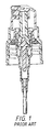
- FIG. 1 it illustrates an atomizer manufactured by Coster Tecnologie Speciali S.P.A. wherein the shoulder of the moveable valve is designed to be inclined
- FIG. 1 illustrates an atomizer manufactured by Coster Tecnologie Speciali S.P.A. wherein the shoulder of the moveable valve is designed to be inclined
- the moveable valve cannot efficiently overcome the opposite compression force created by a spring to make a valve head disengage from a corresponding exhaust hole. Therefore, in operation, a user needs to apply a quite strong force to have the moveable valve moved downward and then to allow the pressurized liquid to be sprayed ont of the atomizer.
- the present invention relates to an improved moveable valve assembly for liquid atomizers which mainly comprises a piston body and a moveable valve body including an upper solid rod and a lower hollow sleeve.
- the upper solid rod consists of three rod portions each having a different diameter from the other such that the intersection between any two of three rod portions may be respectively formed into a tapered shoulder, a recess or a socket with a flattened shoulder to serve as pressure concentrating points whereby the pressure generated by the pressurized liquid can be efficiently applied to those pressureconcentrating points in order to overcome the compression force provided by a spring located under the moveable valve body and in turn to enable a valve head to disengage from a corresponding exhaust hole.
- the lower hollow sleeve is provided at the lower end of its vertical side with an outward projection such that the pressure generated by the pressurized liquid can be applied to the upper side of the projection to force the moveable valve body downward while the pressure applied to the inclined extension makes an inner arcuate flange of the inclined extension closely contact a valve hole so as to achieve a fluidtight effect, and in turn so expedite the formation of pressured liquid in a compressed chamber.
- the upper periphery of the sleeve may be provided with a thick solid portion, the top side of which is formed with a plurality of tooth-shaped annular portions whereby upon operation the thick solid portion can apply a larger compression force to the liquid contained in a compressed chamber and then the pressurized liquid will effectively force the moveable valve to more downward with the aid of the tooth-shaped annvlar portions as well as a corresponding inverted v-shaped groove and corresponding trumpet-shaped inner annular portion respectively formed in the lower side of the piston body such that a triangular valve body may simultaneously disengage from a corresponding exhaust hole to allow the pressarized liquid to be sprayed out of the atomizer through a hollew tubular portion.
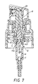
- the moveable valve assembly for liquid atomizers of the first preferred embodiment of the present invention mainly comprises a piston body (B) and an moveable valve body (A) consisting of an upper solid rod (A1) and a lower cylindrical sleeve (A2).
- the upper solid rod (A1) is received into a piston body (B) in such a manner that a triangular exhaust valve head (A101) at the top of said rod (A1) closely contact an exhaust hole located at the bottom of a hollow tubular portion (B1) of the piston body (B) to restrict the liquid to flow into the lower space of the tubular portion (B1).
- a triangular exhaust valve head (A101) at the top of said rod (A1) closely contact an exhaust hole located at the bottom of a hollow tubular portion (B1) of the piston body (B) to restrict the liquid to flow into the lower space of the tubular portion (B1).
- the piston body (B) together with the moveable valve body (A) are driven downward.
- the upper solid rod (A1) of the moveable valve body (A) is designed in such a manner that said rod (A1) mainly consists of a first rod portion (A11), a second rod portion (A12) and a third rod portion (A11) is formed into a triangular valve head (A101) while the intersection between the first rod portion (A11) and the second rod portion (A12) is formed with a taperes shoulder (A102) acting as a first pressure concentrating point.
- the intersection between the second rod portion (A12) and the third rod portion (A13) also has a tapered shoulder (A103) and a projection shoulder (A104).
- An inverted triangular recess (A105) is formed between said tapered shoulder (A103) and projection shoulder (A104) in order to both receive more liquid therein and serve as a second pressure concentrating point.
- the tapered shoulder (A103) can further direct the vertical force component of the force provided by the pressurized liquid to the recess (A105).
- the lower end of the third rod portion (A13) possesses a tapered shoulder (A106) similar to the tapered shoulder (A103) of the second rod portion (A12), and further forms with the upper end of a sleeve (A2) a flattened shoulder (A202) as well as a flange (A203) to serve as a third pressure concentrating point.
- the tapered shoulder (A106) of the third rod portion (A13), in addition to having the ability of directing the force as the aforesaid tapered shoulder (A103) does, is designed to cooperate with the upper end of the sleeve (A2) so as to provide a thicker portion (A204) which shall not be inwardly deformed when the sleeve (A2) of the moveable valve body (A) is compressed under high pressure.
- the lower end of the vertical side (A205) of the sleeve (A2) is provided with an outward projection (A206).
- the upper side of said projection (A26) is used to concentrate the pressure applied thereto and serve as a fourth pressure concentrating point.
- the lower side of said projection (A206) has an inwardly inclined extension (A207) which is provided at its interior with an inner arcuate flange (A201).
- A207 inwardly inclined extension
- the inclined extension (A207) below said projection (A206) is inwardly compressed under the horizontal force applied to the inclined surface thereof. Due to such an inward compression action, the extension (A207) can closely contact a corresponding valve hole to prevent the liquid from leaking into the compressed chamber during the compression stroke.
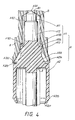
- FIG. 6 shows a longitudinal sectional view of the second preferred embodiment of the present invention wherein a thick solid portion (A3) is formed on the upper periphery of the sleeve (A2).
- the thick solid portion (A3) is formed by extending outward from the vertical side (A21) of the sleeve (A2) a solid portion with a larger diameter in comparison with the diameter of the sleeve (A2).
- the lower side of the thick solid portion (A3) is formed into an inclined portion (A31) and the upper side thereof is provided with a plurality of concentric tooth-shaped annular portions , for example , a first annular portion (A34), a second annalar portions (A33) and a third annular portion (A32) as shown in FIG. 6, to guide the liquid applied thereto.
- the piston body (B) is provided at its lower side with an inverted V-shaped groove (B2) and a trumpet-shaped inner annular portion (B3) respectively corresponding to the aforesaid annular portions of the thick solid portion (A3).
- the pressurized effeet will be come more significant with the provision of the thick solid portion (A3).
- the pressurized liquid below the thick solid portion (A3) will be forced to flow upward through the space formed between the thick solid portion (A3) and the wall (C1) of the compressed chamber (C).
- the upward pressurized liquid will first contact the inverted V-shaped groove (B2) of the piston body (B) and be directed to the first annular portion (A34) of the thick solid portion (A3) to force the moveable valve (A) downward.
- the pressurized liquid coming from the first annular portion (A34) will be directed to the inner annular groove (B3) of the piston body (B) and then be directed to the third annular portion (A32) of the thick solid portion (A3) to further force the moveable valve (A) downward.
- the pressuized liquid will be directed upward through the space formed between the third rod portion (A13) and the inner wall of the piston body (B). Since the above mentioned various actions are completed simultaneously the pressure applied to the moveable valve (A) is both concentrative and effective such that the moveable valve (A) can easily overcome the opposite compression force generated by the spring (E) and then move downward.
- the moveable valve (A) will continue to move downward to make the triagular valve head disengage from the exhaust hole (B101) so that the pressurized liquid can be sprayed out of the atormizer through the hollow tubular portion (B1).
- the special arrangement of the tooth-shaped annular portions also will prevent the l iquid from easily sliding downward along the inclined portion so as to expedite the formation of the pressure concentration effect.
- the present invention provides at least four pressure concentrating points respectively located at four different positions such that the presure provided by the pressurized liquid can be efficiently applied to said four pressure concerntrating points whereby the moveable valve (A) in turn is driven downward to disengage the valve head (A101) from the exhaust hole (B101) whereby the pressurized liquid can be sprayed out from the atomizer through the hollow tubular portion (B1) of the piston body (B).
- the thick solid portion (A3) of the sleeve (A2) possesses a larger volume, the capability of pressurizing the liquid contained in the compressed chamber will be significently increased
- the improved structure achieved by the provision of the tooth-shaped annular portions (A32), (A33) and (A34), as well as the inverted V-shaped groove (B2) and the trumpet-shaped inner annular portion (B3) will facilitate the application of the pressurized liquid to the moveable valve (A) on a simultaneous and continuous manner so as to force the moveable valve (A) to overcome the opposite force generated by the spring (E) and then to disengage the valve head from the exhaust hole (B101) Accordingly it is believed that the present invention can effectively eliminate the drawbacks existing in the prior art and thus successfully provide an improved atomizer.
Landscapes
- Containers And Packaging Bodies Having A Special Means To Remove Contents (AREA)
Applications Claiming Priority (3)
| Application Number | Priority Date | Filing Date | Title |
|---|---|---|---|
| US07/277,270 US4938392A (en) | 1988-11-29 | 1988-11-29 | Anti-leakage structure for a liquid atomizer |
| EP90101811 | 1990-01-30 | ||
| EP90101811A EP0439648B1 (de) | 1988-11-29 | 1990-01-30 | Lecksichere Anordnung für Flüssigkeitszerstäuber |
Publications (2)
| Publication Number | Publication Date |
|---|---|
| EP0446401A1 true EP0446401A1 (de) | 1991-09-18 |
| EP0446401B1 EP0446401B1 (de) | 1995-03-15 |
Family
ID=26124905
Family Applications (1)
| Application Number | Title | Priority Date | Filing Date |
|---|---|---|---|
| EP90106795A Expired - Lifetime EP0446401B1 (de) | 1988-11-29 | 1990-04-09 | Bewegliche Ventilanordnung für Flüssigkeitszerstäuber |
Country Status (1)
| Country | Link |
|---|---|
| EP (1) | EP0446401B1 (de) |
Cited By (1)
| Publication number | Priority date | Publication date | Assignee | Title |
|---|---|---|---|---|
| US5370317A (en) * | 1991-06-28 | 1994-12-06 | Glaxo Group Limited | Atomizing device for producing a spray from a liquid under pressure |
Citations (3)
| Publication number | Priority date | Publication date | Assignee | Title |
|---|---|---|---|---|
| FR2349749A1 (fr) * | 1976-04-30 | 1977-11-25 | Emson Res | Pompe de vaporisateur |
| FR2512517A1 (fr) * | 1981-09-04 | 1983-03-11 | Aerosol Inventions Dev | Pompe-valve pour la distribution de liquides sous pression et procede de remplissage de recipients equipes d'une telle pompe-valve |
| US4821928A (en) * | 1987-09-25 | 1989-04-18 | Su Cheng Y | Moveable valve structure for perfume atomizers |
-
1990
- 1990-04-09 EP EP90106795A patent/EP0446401B1/de not_active Expired - Lifetime
Patent Citations (3)
| Publication number | Priority date | Publication date | Assignee | Title |
|---|---|---|---|---|
| FR2349749A1 (fr) * | 1976-04-30 | 1977-11-25 | Emson Res | Pompe de vaporisateur |
| FR2512517A1 (fr) * | 1981-09-04 | 1983-03-11 | Aerosol Inventions Dev | Pompe-valve pour la distribution de liquides sous pression et procede de remplissage de recipients equipes d'une telle pompe-valve |
| US4821928A (en) * | 1987-09-25 | 1989-04-18 | Su Cheng Y | Moveable valve structure for perfume atomizers |
Cited By (2)
| Publication number | Priority date | Publication date | Assignee | Title |
|---|---|---|---|---|
| US5370317A (en) * | 1991-06-28 | 1994-12-06 | Glaxo Group Limited | Atomizing device for producing a spray from a liquid under pressure |
| US5370318A (en) * | 1991-06-28 | 1994-12-06 | Glaxo Group Limited | Atomizing nozzle for producing a spray from a liquid under pressure |
Also Published As
| Publication number | Publication date |
|---|---|
| EP0446401B1 (de) | 1995-03-15 |
Similar Documents
| Publication | Publication Date | Title |
|---|---|---|
| US4821928A (en) | Moveable valve structure for perfume atomizers | |
| US4606480A (en) | Liquid sprayer | |
| CA1289110C (en) | Manually actuated dispensing pump | |
| JPS6028529Y2 (ja) | 蓄圧タイプの噴霧器 | |
| JP3136107B2 (ja) | 予備圧縮ポンプ・スプレー | |
| JPS6027470Y2 (ja) | ポンプデイスペンサ | |
| JPH07503927A (ja) | 改良型予圧縮ポンプ | |
| US5641097A (en) | Manual precompression pump for the spraying of a liquid and a dispensing unit fitted with such a pump | |
| JPH04225858A (ja) | 噴霧ポンプ | |
| DE19712256B4 (de) | Zerstäuber mit sich hin- und herbewegenden Kolben | |
| EP0446401B1 (de) | Bewegliche Ventilanordnung für Flüssigkeitszerstäuber | |
| DE4004653A1 (de) | Fluessigkeitsspruehvorrichtung | |
| US3231153A (en) | Multiple spray rate pressurized package dispenser | |
| HK175295A (en) | A moveable valve assembly for liquid atomizers | |
| AU652288B2 (en) | An improved moveable valve assembly for liquid atomizers | |
| KR940005561Y1 (ko) | 액체분무기용의 개량된 가동밸브 어셈블리 | |
| CA2011865A1 (en) | Moveable valve assembly for liquid atomizers | |
| WO2025148907A1 (zh) | 一种香水雾化泵 | |
| US5370280A (en) | Valve for a sprayer | |
| CN218056508U (zh) | 一种喷雾泵 | |
| JPH0838957A (ja) | ポンプ噴霧機 | |
| JPH06219478A (ja) | 予圧ポンプを有する液体噴霧用アッセンブリ | |
| CA1153992A (en) | Air-pressurized sprayer | |
| JPS6043183B2 (ja) | プツシユボタンタイプの噴霧器 | |
| CN222606756U (zh) | 一种喷雾泵 |
Legal Events
| Date | Code | Title | Description |
|---|---|---|---|
| PUAI | Public reference made under article 153(3) epc to a published international application that has entered the european phase |
Free format text: ORIGINAL CODE: 0009012 |
|
| AK | Designated contracting states |
Kind code of ref document: A1 Designated state(s): AT BE CH DE DK ES FR GB GR IT LI LU NL SE |
|
| 17P | Request for examination filed |
Effective date: 19920311 |
|
| 17Q | First examination report despatched |
Effective date: 19930527 |
|
| GRAA | (expected) grant |
Free format text: ORIGINAL CODE: 0009210 |
|
| AK | Designated contracting states |
Kind code of ref document: B1 Designated state(s): AT BE CH DE DK ES FR GB GR IT LI LU NL SE |
|
| PG25 | Lapsed in a contracting state [announced via postgrant information from national office to epo] |
Ref country code: IT Free format text: LAPSE BECAUSE OF FAILURE TO SUBMIT A TRANSLATION OF THE DESCRIPTION OR TO PAY THE FEE WITHIN THE PRESCRIBED TIME-LIMIT;WARNING: LAPSES OF ITALIAN PATENTS WITH EFFECTIVE DATE BEFORE 2007 MAY HAVE OCCURRED AT ANY TIME BEFORE 2007. THE CORRECT EFFECTIVE DATE MAY BE DIFFERENT FROM THE ONE RECORDED. Effective date: 19950315 Ref country code: FR Effective date: 19950315 Ref country code: GR Free format text: LAPSE BECAUSE OF FAILURE TO SUBMIT A TRANSLATION OF THE DESCRIPTION OR TO PAY THE FEE WITHIN THE PRESCRIBED TIME-LIMIT Effective date: 19950315 Ref country code: NL Free format text: LAPSE BECAUSE OF NON-PAYMENT OF DUE FEES Effective date: 19950315 Ref country code: ES Free format text: THE PATENT HAS BEEN ANNULLED BY A DECISION OF A NATIONAL AUTHORITY Effective date: 19950315 Ref country code: BE Effective date: 19950315 Ref country code: DK Effective date: 19950315 Ref country code: AT Effective date: 19950315 |
|
| REF | Corresponds to: |
Ref document number: 119808 Country of ref document: AT Date of ref document: 19950415 Kind code of ref document: T |
|
| REF | Corresponds to: |
Ref document number: 69017889 Country of ref document: DE Date of ref document: 19950420 |
|
| PG25 | Lapsed in a contracting state [announced via postgrant information from national office to epo] |
Ref country code: LU Free format text: LAPSE BECAUSE OF NON-PAYMENT OF DUE FEES Effective date: 19950430 |
|
| PGFP | Annual fee paid to national office [announced via postgrant information from national office to epo] |
Ref country code: CH Payment date: 19950524 Year of fee payment: 6 |
|
| PG25 | Lapsed in a contracting state [announced via postgrant information from national office to epo] |
Ref country code: SE Effective date: 19950615 |
|
| PG25 | Lapsed in a contracting state [announced via postgrant information from national office to epo] |
Ref country code: DE Effective date: 19950617 |
|
| EN | Fr: translation not filed | ||
| NLV1 | Nl: lapsed or annulled due to failure to fulfill the requirements of art. 29p and 29m of the patents act | ||
| PLBE | No opposition filed within time limit |
Free format text: ORIGINAL CODE: 0009261 |
|
| STAA | Information on the status of an ep patent application or granted ep patent |
Free format text: STATUS: NO OPPOSITION FILED WITHIN TIME LIMIT |
|
| 26N | No opposition filed | ||
| PG25 | Lapsed in a contracting state [announced via postgrant information from national office to epo] |
Ref country code: CH Effective date: 19960430 Ref country code: LI Effective date: 19960430 |
|
| REG | Reference to a national code |
Ref country code: CH Ref legal event code: PL |
|
| PGFP | Annual fee paid to national office [announced via postgrant information from national office to epo] |
Ref country code: GB Payment date: 19970401 Year of fee payment: 8 |
|
| PG25 | Lapsed in a contracting state [announced via postgrant information from national office to epo] |
Ref country code: GB Free format text: LAPSE BECAUSE OF NON-PAYMENT OF DUE FEES Effective date: 19980409 |
|
| GBPC | Gb: european patent ceased through non-payment of renewal fee |
Effective date: 19980409 |