EP0445666A1 - Roof covering composed of roof tiles with overlapping longitudinal- and transversal edges - Google Patents
Roof covering composed of roof tiles with overlapping longitudinal- and transversal edges Download PDFInfo
- Publication number
- EP0445666A1 EP0445666A1 EP91103105A EP91103105A EP0445666A1 EP 0445666 A1 EP0445666 A1 EP 0445666A1 EP 91103105 A EP91103105 A EP 91103105A EP 91103105 A EP91103105 A EP 91103105A EP 0445666 A1 EP0445666 A1 EP 0445666A1
- Authority
- EP
- European Patent Office
- Prior art keywords
- roof covering
- roof
- sealing
- plate
- plates
- Prior art date
- Legal status (The legal status is an assumption and is not a legal conclusion. Google has not performed a legal analysis and makes no representation as to the accuracy of the status listed.)
- Granted
Links
- 238000007789 sealing Methods 0.000 claims abstract description 113
- 239000011810 insulating material Substances 0.000 claims abstract description 5
- 239000012528 membrane Substances 0.000 claims description 3
- 239000007787 solid Substances 0.000 claims description 3
- 238000009413 insulation Methods 0.000 abstract description 9
- XLYOFNOQVPJJNP-UHFFFAOYSA-N water Substances O XLYOFNOQVPJJNP-UHFFFAOYSA-N 0.000 description 10
- 230000002787 reinforcement Effects 0.000 description 5
- 239000000853 adhesive Substances 0.000 description 4
- 230000001154 acute effect Effects 0.000 description 3
- 230000001070 adhesive effect Effects 0.000 description 3
- 230000000694 effects Effects 0.000 description 3
- 230000035515 penetration Effects 0.000 description 3
- 239000004033 plastic Substances 0.000 description 3
- 238000009423 ventilation Methods 0.000 description 3
- 229920006328 Styrofoam Polymers 0.000 description 2
- 239000000463 material Substances 0.000 description 2
- 239000008261 styrofoam Substances 0.000 description 2
- 238000009825 accumulation Methods 0.000 description 1
- 238000005452 bending Methods 0.000 description 1
- 239000004927 clay Substances 0.000 description 1
- 230000003247 decreasing effect Effects 0.000 description 1
- 238000005516 engineering process Methods 0.000 description 1
- 238000010304 firing Methods 0.000 description 1
- 239000003292 glue Substances 0.000 description 1
- 230000001771 impaired effect Effects 0.000 description 1
- 238000007373 indentation Methods 0.000 description 1
- 239000004570 mortar (masonry) Substances 0.000 description 1
- 239000000123 paper Substances 0.000 description 1
- 239000002985 plastic film Substances 0.000 description 1
- 229920006255 plastic film Polymers 0.000 description 1
- 239000000843 powder Substances 0.000 description 1
- 230000003014 reinforcing effect Effects 0.000 description 1
- 208000000649 small cell carcinoma Diseases 0.000 description 1
Images


Classifications
-
- E—FIXED CONSTRUCTIONS
- E04—BUILDING
- E04D—ROOF COVERINGS; SKY-LIGHTS; GUTTERS; ROOF-WORKING TOOLS
- E04D12/00—Non-structural supports for roofing materials, e.g. battens, boards
-
- E—FIXED CONSTRUCTIONS
- E04—BUILDING
- E04D—ROOF COVERINGS; SKY-LIGHTS; GUTTERS; ROOF-WORKING TOOLS
- E04D1/00—Roof covering by making use of tiles, slates, shingles, or other small roofing elements
- E04D1/28—Roofing elements comprising two or more layers, e.g. for insulation
-
- E—FIXED CONSTRUCTIONS
- E04—BUILDING
- E04B—GENERAL BUILDING CONSTRUCTIONS; WALLS, e.g. PARTITIONS; ROOFS; FLOORS; CEILINGS; INSULATION OR OTHER PROTECTION OF BUILDINGS
- E04B7/00—Roofs; Roof construction with regard to insulation
- E04B7/20—Roofs consisting of self-supporting slabs, e.g. able to be loaded
- E04B7/22—Roofs consisting of self-supporting slabs, e.g. able to be loaded the slabs having insulating properties, e.g. laminated with layers of insulating material
- E04B7/225—Roofs consisting of self-supporting slabs, e.g. able to be loaded the slabs having insulating properties, e.g. laminated with layers of insulating material the slabs having non-structural supports for roofing materials
-
- E—FIXED CONSTRUCTIONS
- E04—BUILDING
- E04D—ROOF COVERINGS; SKY-LIGHTS; GUTTERS; ROOF-WORKING TOOLS
- E04D1/00—Roof covering by making use of tiles, slates, shingles, or other small roofing elements
- E04D1/29—Means for connecting or fastening adjacent roofing elements
- E04D1/2907—Means for connecting or fastening adjacent roofing elements by interfitted sections
- E04D1/2914—Means for connecting or fastening adjacent roofing elements by interfitted sections having fastening means or anchors at juncture of adjacent roofing elements
- E04D1/2916—Means for connecting or fastening adjacent roofing elements by interfitted sections having fastening means or anchors at juncture of adjacent roofing elements the fastening means taking hold directly on adjacent elements of the same row
-
- E—FIXED CONSTRUCTIONS
- E04—BUILDING
- E04D—ROOF COVERINGS; SKY-LIGHTS; GUTTERS; ROOF-WORKING TOOLS
- E04D13/00—Special arrangements or devices in connection with roof coverings; Protection against birds; Roof drainage ; Sky-lights
- E04D13/16—Insulating devices or arrangements in so far as the roof covering is concerned, e.g. characterised by the material or composition of the roof insulating material or its integration in the roof structure
- E04D13/1606—Insulation of the roof covering characterised by its integration in the roof structure
- E04D13/1612—Insulation of the roof covering characterised by its integration in the roof structure the roof structure comprising a supporting framework of roof purlins or rafters
-
- E—FIXED CONSTRUCTIONS
- E04—BUILDING
- E04D—ROOF COVERINGS; SKY-LIGHTS; GUTTERS; ROOF-WORKING TOOLS
- E04D1/00—Roof covering by making use of tiles, slates, shingles, or other small roofing elements
- E04D1/02—Grooved or vaulted roofing elements
- E04D1/04—Grooved or vaulted roofing elements of ceramics, glass or concrete, with or without reinforcement
Definitions
- a roof covering in question is waterproof.
- additional measures are necessary to prevent the penetration of flying snow.
- Known measures are so-called underlays made of a plastic film, cardboard docks attached under the roofing panels and seals made of mortar or a foamed plastic.
- These additional measures make roofing considerably more expensive because they are also labor-intensive.
- the sarking membrane must be led to the gutter so that the moisture can drain away unhindered.
- Another disadvantage can be seen in the fact that the replacement of roofing panels is only possible from the outside, if you want to avoid cutting the underlay.
- the thermal insulation is relatively low.
- a roof covering plate which is provided on the lower side facing away from the weather side with circumferential webs, through which an insulating chamber is formed, into which an insulating core can be inserted, or by placing the roof covering plate on one Insulating plate is formed.
- the the weather-side outer surface of each roofing slab is a smooth surface.
- a roof covering consisting of such roof covering plates does indeed improve the thermal insulation, but the penetration of flying snow is also possible with such a roof covering.
- the present invention has for its object to develop a roof covering according to the preamble of claim 1 so that with simple, inexpensive means, the tightness is increased so that no flying or powder snow can penetrate through the joints. In addition, there should be no significant additional work when laying the roofing slabs. Adequate thermal insulation should also be possible if necessary.
- the object is achieved by the features listed in the characterizing part of claim 1. It is now possible to simultaneously install the sealing panels when laying the roof covering panels. The support surfaces fix them in place at the eaves-side end. At the other end on the ridge side, if the roof covering panels are designed accordingly, they are clamped between the underside and the roof batten by their own weight. This means that slipping or moving is no longer possible. In addition, the roof covering ensures that the moisture is conducted directly to the roof covering plate that adjoins the eaves side.
- the level of each roofing slab is at an angle to the rafters.
- the sealing plates also run obliquely to the outer surfaces of the rafters, the included angle being a small acute angle. This angle should be chosen by appropriate design of the roofing panels so that the sealing panels run parallel to the levels of the roofing slabs. So that the sealing plates rest on the ridge-side edge over the entire surface of the respective roof batten, the ridge-side edges of the sealing plates are designed as correspondingly inclined inclined surfaces.
- the sealing plates can be solid in cross section or profiled. Preferred cross-sections are, for example, wavy or trapezoidal cross-sections, since this simply creates the possibility that the sealing plates also overlap at the longitudinal edges. This significantly increases the tightness.
- the sealing panels can then also be installed. Although an insulating effect is also achieved if the sealing plates are relatively thin, it is provided that they consist of a thermally insulating material. They should then be much thicker than if they only have a sealing function. These plates could then also be referred to as insulating plates, the thickness of which could be in the range of 2 to 3 centimeters, for example.
- each sealing plate has a cantilever arm projecting opposite the roof batten in the direction of the ridge, which engages under the next sealing plate following the ridge, and that the cantilever arm on that of the respective roof covering plate facing side has a groove running parallel to the roof batten, in which the head of the roof covering plate above it engages and that on the side facing the rafters a bearing surface is provided which is in contact with the surface of the roof batten which runs perpendicular to the rafters and faces the ridge.
- each sealing plate has a recess on each of the two longitudinal edges such that one recess is assigned to the top and the other recess of the same cross section to the underside of the sealing plate for overlapping the longitudinal edges of two insulating plates lying one above the other. So that the plates are pulled together, each recess is assigned a groove, the outer surface of which is an inclined surface.
- each roof covering plate is offset relative to the adjacent outer surfaces in the direction of the substructure in order to form a stop standing at right angles or approximately at right angles to the roof surface and transversely to the longitudinal edges of the roof covering plate, and that this stop is used to drain moisture is profiled in the transverse fold formed by the bearing surface 15 and the stop 34, for example is wave-shaped or is provided with grooves.
- the eaves-side end edge of each sealing plate is supported, while at the ridge-side end it rests exclusively on the batten.
- the wave-shaped design of the stop surface is advantageous because it allows moisture to flow away from the insulating plate into the transverse fold formed by the support surface and the stop.
- the bearing surface is a profiled surface with raised partial surfaces, so that the raised partial surfaces for the additional sealing of the interior of the building slightly press into the deformable sealing plate, and that the raised partial surfaces are preferably through a transverse to the longitudinal edges of the roof covering plate are formed web, the weather-side edge of which, in relation to the cross section, runs in a radius.
- the sealing plates are made, for example, from the known styrofoam. The raised areas respectively the web is then to be seen as a seal in connection with the depression reached. The radius of the web prevents the sealing plate from being cut into.
- the height of the stop at right angles or approximately at right angles to the roof surface is slightly smaller than the thickness of the sealing plate 16.
- the height of the stop could preferably be 10 percent less than the thickness of the sealing plate.
- the roof covering according to the invention What is essential here is the transverse fold formed on the entire width of the roof covering plate from the support surface.
- This arrangement of the transverse fold which can be designed as a simple but also a double fold, means that the sealing plate is located below the tile over the entire width of the deck.
- the arrangement of the continuous transverse fold on the tile head creates a support for the sealing plate in two directions, namely at right angles and parallel to the roof surface. This additionally supports the sealing plate at the lower end. At the upper end, i.e. towards the ridge, there is only a sliding support on the roof batten. Due to the variable support lengths on the roof batten, uneven, unavoidable roof batten distances are absorbed without the tightness being impaired.
- moisture that gets onto the sealing panels is conducted through the cross fold on the tile head over the side rebate to the roof covering panel closest to the eaves.
- the penetration of moisture can be caused, for example, by flying snow or by a leak in the roof covering.
- the sealing plates are made from the plates marketed under the trade name Styrofoam, it should be achieved in the designs according to claims 11 to 13 that the unevenness of the roof covering plate can be compensated for without reducing the sealing effect.
- Such bumps are unavoidable with fired roofing tiles.
- each individual sealing plate is dewatered itself. So that there can be no accumulation of water.
- the deformability of the sealing plates creates small-cell, closed chambers, which not only cause direct water drainage to the next roof covering plate underneath, but also build-up pressure in flying snow, which largely prevents the possible entry of flying snow from the outset.
- the sealing panels can be easily cut and easily connected to roof openings. Furthermore, it is not necessary, as in the known underlays, to connect the individual sealing plates to the gutter. Furthermore, the additional ventilation cross-sections on the ridge, which are also necessary for underlays, are also eliminated.
- the roof covering according to the invention is particularly suitable for roofing, since the new roof covering is only very slightly higher than the unsealed previous roof covering. The unavoidable differences in height result in joints that can be sealed easily and inexpensively.
- the lower region of the water-carrying fold 11 is conical.
- the cross section becomes larger towards the lower eaves-side end, since the outer side web and the other edge web assigned to this side diverge in opposite directions.
- the edge web 18 of the top fold 12 and the edge web assigned to this side run approximately parallel to the edge web of the water-carrying fold 11.
- the upper sides can be chamfered.
- the different appearances due to triangles 21 of different heights are shown in FIGS. 4 to 6.
- Fig. 7 shows a first embodiment of a roof covering in a section parallel to the rafters with sealing plates 16, which are relatively thin.
- the thickness of a sealing plate 16 is a little less than the wall thickness of the roof covering plate in the central region, ie in the region that is free of webs.
- the upper surface of the rafters facing the roofing panels 10 is identified by the solid line 22.
- the roof battens running parallel to and at a distance from one another and transversely to the rafters are identified by reference numerals 23. 7 shows that the sealing plates 16 run parallel to the outer surfaces of the roofing plates 10.
- each sealing plate 16 on the eaves side is supported on the bearing surface 15 of the roof covering plate 10.
- the ridge-side end of each sealing plate 16 lies between the edge webs 18 running transversely to the longitudinal sides and the respective roof batten 23.
- each sealing plate 10 can correspond to the covering width of the roof covering plate 10, or can be an integral multiple thereof.
- the width of the support surface 15 also corresponds to the cover width of the roof covering plate 10.
- the sealing plates 16 are not fastened to the substructure, but are only clamped by the weight of the roof covering plates 10.
- the sealing plates 16 can be made of paper or plastic. 8 to 10 show three preferred cross-sectional shapes. The cross section according to FIG. 8 is like a corrugated cardboard and consequently consists of two carrier webs 24 and a reinforcing web 25. FIG.
- sealing plates 16 of greater thickness which can be between two and three centimeters.
- the sealing plates 16 are made from a thermally insulating material, for example from a foamed plastic. They are therefore insulating panels that form a full-surface thermal insulation layer.
- the sealing plates 16 run parallel to the weather-side surface which is kept free of webs.
- the distance between the support surface 15 and the outer surfaces of the roof covering plate 10 is greater than in the embodiment according to FIG. 7.
- the edge region of each sealing plate 16 facing the substructure has a recess 28 which serves as a full-surface support on the roof batten 23 appropriately inclined inclined surface is formed.
- FIG. 12 shows the sealing plate 16 according to FIG. 11 in cross section.
- the sealing plate 16 is in turn provided on both sides with covering webs 26, 27.
- a groove 29 is also provided towards the open side, the outer boundary of which is an inclined surface, so that the sealing plates which are lined up next to one another are pulled together.
- each sealing plate 16 is wedge-shaped, the thickness decreasing towards the edge on the ridge side.
- Each sealing plate 16 is designed in such a way that the outer surface facing the roof covering plate 10 is parallel and at a distance from the web-free surface of the roof covering plate 10.
- the lower surface facing the substructure runs parallel and at a short distance from the upper surface 22 of the rafters. This design achieves better thermal insulation.
- the eaves-side end face of each sealing plate 16 is provided with a profile groove extending transversely to the longitudinal edges, in which the heads 14 or webs lie.
- the adjacent roof batten 23 forms an abutment for the sealing plate 16. It is therefore not only supported on the bearing surface 15, but also on the eave-side surface of the respective roof batten 23.
- the cross section of the sealing plate 16 is in accordance with FIG. 13. Thereafter, the longitudinal edges are oppositely step-shaped, the upper steps forming the covering webs 26, 27, which in turn are each provided with a groove 29, the outer boundary of which is also formed by an inclined surface.
- each sealing plate 16 has a cantilever arm 30 which projects in relation to the associated roof batten 23 in the direction of the ridge.
- This sealing plate in turn has a recess 28 in order to hang it on the roof batten 23.
- the cantilever arm 30 On the weather side and offset in the direction of the ridge-side end, the cantilever arm 30 has a groove 31 which runs transversely to the longitudinal sides and into which the heads 14 of the roof covering plates engage.
- the roof covering plate 10 has the flat support surface 15 on the ridge-side edge.
- the broken line 32 shows the position of the cantilever arm 30 in the unloaded state. When loaded by the roofing panels 10, the cantilever arm is bent in the direction of the substructure. With this design, the contacting surfaces are pressed together by the restoring forces, so that a special sealing effect is achieved.
- each insulating gap 16 is in turn provided with a cantilever arm 30. The remaining part of each insulating plate 16 projects beyond two fields formed by three roof battens 23. This results in an overlap, so that the thermal insulation layer formed from the sealing plates 16 can be viewed in the sense of a two-layer layer.
- each roof covering plate 10 is also provided with the recess 28 and a groove 31 for the heads 14 which is offset from it.
- the advantage of this embodiment is that the sealing plates 16 can be laid in a set, ie offset from one another, so that there is no lateral fold.
- the surface of each insulating plate 16 assigned to the roof covering plate 10 runs parallel to the web-free area of the roof covering plate 10, while the surface facing the substructure runs at an acute angle to the upper surface of the rafters.
- the embodiment according to FIGS. 16 and 17 offers the advantage of a larger thickness. In the embodiment according to FIG.
- each insulating plate 16 in turn extends over two fields delimited by three roof battens 23.
- the cantilever is missing in this version.
- the sealing plates 16 are also installed in this association.
- the cross-sectional shape corresponds to FIG. 14.
- more than two fields can also be covered.
- the number of fields always corresponds to the number of individual layers.
- FIG. 7a differs from the embodiment according to FIG. 7 by a sealing strip 33 which is arranged on the side facing away from the weather on the eaves-side edge of the sealing plate 16 and extends transversely to the longitudinal edges.
- This sealing strip is made of an elastically deformable material in order to compensate for height differences in the support surfaces 15 which are caused by production technology.
- the longitudinal edges of the sealing plates 15 can be provided with a self-adhesive strip or with a strip made of an adhesive. This makes it possible to glue the individual sealing plates 15 together at the longitudinal edges. If an adhesive is used, it is expedient if the congruent adhesive strips stick together without moistening.
- each roof covering plate 10 has two support surfaces 15 running parallel and at a distance from one another.
- only one bearing surface 15 is used.
- the bearing surface 15 is assigned a stop 17a running transversely to the longitudinal edges, against which the eaves-side end edge of the sealing plate 16 can abut. Despite this attack, the water can drain away.
- Figures 19 and 20 show in longitudinal section two further embodiments of the heads of the roofing panels 10. From these figures it can be clearly seen that the support surface 15 is not a flat surface, but that it has raised partial surfaces, that is, the raised partial surfaces are facing the weather side in front. As can also be seen, the bearing surface 15 jumps towards the substructure in relation to the adjacent outer surfaces. This creates a surface approximately perpendicular to the roof surface, which can be seen in the sense of a stop 34 for the sealing plate 16.
- the ridge-side boundary of the bearing surface 15 is formed by a web 35 which runs transversely to the longitudinal edges of the roof covering plate 10 and which projects towards the weather side with respect to the actual bearing surface 15. This web 35 is triangular in cross-section, the upper edge running in a radius.
- the bearing surface 15 is angled, so that the height of this web 35 is lower than in the embodiment according to FIG. 19.
- the head of the roofing plate 10 in the embodiment according to FIG. 20 is designed such that the assigned sealing plate 16 is stepped in the front end area of the eaves. This creates two bearing surfaces that increase the tightness. It is clear from the figures that the sealing plate 16 presses into the web 35, due to the weight of the roof covering plate, not shown, which lies above the sealing plate 16. This indentation of the web 35, which extends over the entire width of the roof covering plate 10, further increases the tightness, since it can be seen in the sense of a labyrinth seal.
- the height of the stop 34 is a little less than the thickness of the sealing plate 16, so that said sealing plate 16 can be pressed in under a load.
Landscapes
- Engineering & Computer Science (AREA)
- Architecture (AREA)
- Civil Engineering (AREA)
- Structural Engineering (AREA)
- Physics & Mathematics (AREA)
- Electromagnetism (AREA)
- Roof Covering Using Slabs Or Stiff Sheets (AREA)
Abstract
Description
Die vorliegende Erfindung betrifft eine Dacheindeckung gemäß dem Oberbegriff des Anspruches 1.The present invention relates to a roof covering according to the preamble of claim 1.
Eine in Frage kommende Dacheindeckung ist wasserdicht. Es sind jedoch zusätzliche Maßnahmen notwendig, um das Eindringen von Flugschnee zu verhindern. Bekannte Maßnahmen sind sogenannte Unterspannbahnen aus einer Kunststoffolie, unter den Dacheindeckungsplatten angebrachte Pappdocken und Abdichtungen aus Mörtel oder einem geschäumten Kunststoff. Diese zusätzlichen Maßnahmen verteuern die Dacheindeckung beträchtlich, da sie auch arbeitsintensiv sind. Die Unterspannbahn muß bis zur Dachrinne geführt werden, damit die Feuchtigkeit ungehindert abfließen kann. Ein weiterer Nachteil ist noch darin zu sehen, daß das Auswechseln von Dacheindeckungsplatten nur von außen möglich ist, sofern man ein Einschneiden der Unterspannbahnen vermeiden will. Außerdem ist die thermische Isolierung relativ gering.A roof covering in question is waterproof. However, additional measures are necessary to prevent the penetration of flying snow. Known measures are so-called underlays made of a plastic film, cardboard docks attached under the roofing panels and seals made of mortar or a foamed plastic. These additional measures make roofing considerably more expensive because they are also labor-intensive. The sarking membrane must be led to the gutter so that the moisture can drain away unhindered. Another disadvantage can be seen in the fact that the replacement of roofing panels is only possible from the outside, if you want to avoid cutting the underlay. In addition, the thermal insulation is relatively low.
Aus der DE-OS 38 22 066 ist eine Dacheindeckungsplatte bekannt, die an der der Wetterseite abgewandten unteren Seite mit umlaufenden Stegen versehen ist, durch die eine Isolierkammer gebildet wird, in die ein Isolierkern gesteckt werden kann, oder die durch Auflegen der Dacheindeckungsplatte auf eine Isolierplatte gebildet wird. Die wetterseitige äußere Fläche jeder Dacheindeckungsplatte ist eine glatte Fläche. Eine aus derartigen Dacheindeckungsplatten bestehende Dacheindeckung stellt zwar eine Verbesserung der thermischen Isolierung dar, jedoch ist auch bei einer derartigen Dacheindeckung das Eindringen von Flugschnee möglich. Der vorliegenden Erfindung liegt die Aufgabe zugrunde, eine Dacheindeckung gemäß dem Oberbegriff des Anspruches 1 so weiter zu entwickeln, daß mit einfachen, preiswerten Mitteln die Dichtigkeit so erhöht wird, da auch kein Flug- oder Pulverschnee durch die Fugen eindringen kann. Außerdem soll bei der Verlegung der Dacheindeckungsplatten keine nennenswerte Mehrarbeit aufkommen. Außerdem soll im Bedarfsfall eine ausreichende thermische Isolierung möglich sein.From DE-OS 38 22 066 a roof covering plate is known, which is provided on the lower side facing away from the weather side with circumferential webs, through which an insulating chamber is formed, into which an insulating core can be inserted, or by placing the roof covering plate on one Insulating plate is formed. The the weather-side outer surface of each roofing slab is a smooth surface. A roof covering consisting of such roof covering plates does indeed improve the thermal insulation, but the penetration of flying snow is also possible with such a roof covering. The present invention has for its object to develop a roof covering according to the preamble of claim 1 so that with simple, inexpensive means, the tightness is increased so that no flying or powder snow can penetrate through the joints. In addition, there should be no significant additional work when laying the roofing slabs. Adequate thermal insulation should also be possible if necessary.
Die gestellte Aufgabe wird durch die im Kennzeichen des Anspruches 1 aufgeführten Merkmale gelöst. Es ist nunmehr möglich, im Zuge der Verlegung der Dacheindeckungsplatten die Dichtungsplatten gleichzeitig mit zu verlegen. Durch die Auflagerflächen werden sie am traufseitigen Ende lagegerecht fixiert. Am anderen firstseitigen Ende werden sie bei entsprechender Auslegung der Dacheindeckungsplatten durch das Eigengewicht zwischen der Unterseite und der Dachlatte festgeklemmt. Dadurch ist ein Verrutschen oder ein Verschieben nicht mehr möglich. Außerdem wird durch die Dacheindeckung noch erreicht, daß die Feuchtigkeit direkt auf die sich zur Traufseite hin anschließende Dacheindeckungsplatte geleitet wird.The object is achieved by the features listed in the characterizing part of claim 1. It is now possible to simultaneously install the sealing panels when laying the roof covering panels. The support surfaces fix them in place at the eaves-side end. At the other end on the ridge side, if the roof covering panels are designed accordingly, they are clamped between the underside and the roof batten by their own weight. This means that slipping or moving is no longer possible. In addition, the roof covering ensures that the moisture is conducted directly to the roof covering plate that adjoins the eaves side.
Bedingt durch die sich überlappenden Querränder der Dacheindeckungsplatten steht die Ebene jeder Dacheindeckungsplatte schräg zu den Sparren. In weiterer Ausgestaltung ist vorgesehen, daß auch die Dichtungsplatten zu den äußeren Flächen der Sparren schräg verlaufen, wobei der eingeschlossene Winkel ein kleiner spitzer Winkel ist. Dieser Winkel sollte durch eine entsprechende Gestaltung der Dacheindeckungsplatten so gewählt werden, daß die Dichtungsplatten parallel zu den Ebenen der Dacheindeckungsplatten verlaufen. Damit die Dichtungsplatten am firstseitigen Rand vollflächig auf der jeweiligen Dachlatte aufliegen, sind die firstseitigen Ränder der Dichtungsplatten als entsprechend geneigte Schrägflächen ausgebildet. Die Dichtungsplatten können im Querschnitt massiv ausgebildet oder profiliert sein. Bevorzugte Querschnitte sind beispielsweise wellenförmige oder trapezförmige Querschnitte, da dadurch in einfacher Weise die Möglichkeit geschaffen wird, daß sich auch die Dichtungsplatten an den Längsrändern überlappen. Dadurch wird die Dichtigkeit noch wesentlich erhöht.Due to the overlapping transverse edges of the roofing slabs, the level of each roofing slab is at an angle to the rafters. In a further embodiment it is provided that the sealing plates also run obliquely to the outer surfaces of the rafters, the included angle being a small acute angle. This angle should be chosen by appropriate design of the roofing panels so that the sealing panels run parallel to the levels of the roofing slabs. So that the sealing plates rest on the ridge-side edge over the entire surface of the respective roof batten, the ridge-side edges of the sealing plates are designed as correspondingly inclined inclined surfaces. The sealing plates can be solid in cross section or profiled. Preferred cross-sections are, for example, wavy or trapezoidal cross-sections, since this simply creates the possibility that the sealing plates also overlap at the longitudinal edges. This significantly increases the tightness.
Es ist bekannt, daß die Dachgeschosse von Altbauten thermisch nicht ausreichend isoliert sind. Im Zuge einer Umdeckung der Dacheindeckungsplatten können dann die Dichtungsplatten zusätzlich mitverlegt werden. Obwohl auch schon eine Isolierwirkung erzielt wird, wenn die Dichtungsplatten relativ dünn sind, ist vorgesehen, daß sie aus einem thermisch isolierenden Material bestehen. Sie sollten dann wesentlich dicker sein als wenn sie nur eine Dichtfunktion haben. Diese Platten könnten dann auch als Isolierplatten bezeichnet werden, deren Dicke könnte beispielsweise im Bereich von 2 bis 3 Zentimetern liegen. Damit aus den Dichtungsplatten eine vollflächige Wärmedämmschicht gebildet werden kann, ist bei einer Ausführung vorgesehen, daß jede Dichtungsplatte einen gegenüber der Dachlatte in Richtung zum First vorstehenden Kragarm aufweist, der die nächste zum First folgende Dichtungsplatte untergreift, und daß der Kragarm an der der jeweiligen Dacheindeckungsplatte zugewandten Seite eine parallel zur Dachlatte verlaufende Nut aufweist, in die der Kopf der darüber liegenden Dacheindeckungsplatte eingreift und daß an der den Sparren zugewandten Seite eine Anlagefläche vorgesehen ist, die mit der senkrecht zum Sparren verlaufenden, dem First zugewandten Fläche der Dachlatte in Berührung steht. Damit keine undichten Fugen entstehen, ist in weiterer Ausgestaltung vorgesehen, daß jede Dichtungsplatte an den beiden Längsrändern jeweils eine Aussparung aufweist, daß die eine Aussparung der Oberseite und die andere querschnittsgleiche Aussparung der Unterseite der Dichtungsplatte zur Überlappung der Längsränder von zwei übereinander liegenden Isolierplatten zugeordnet ist. Damit die Platten aneinander gezogen werden, ist jeder Aussparung jeweils eine Nut zugeordnet, deren äußere Fläche eine Schrägfläche ist.It is known that the top floors of old buildings are not sufficiently thermally insulated. In the course of covering the roof covering panels, the sealing panels can then also be installed. Although an insulating effect is also achieved if the sealing plates are relatively thin, it is provided that they consist of a thermally insulating material. They should then be much thicker than if they only have a sealing function. These plates could then also be referred to as insulating plates, the thickness of which could be in the range of 2 to 3 centimeters, for example. So that a full-surface thermal insulation layer can be formed from the sealing plates, it is provided in one embodiment that each sealing plate has a cantilever arm projecting opposite the roof batten in the direction of the ridge, which engages under the next sealing plate following the ridge, and that the cantilever arm on that of the respective roof covering plate facing side has a groove running parallel to the roof batten, in which the head of the roof covering plate above it engages and that on the side facing the rafters a bearing surface is provided which is in contact with the surface of the roof batten which runs perpendicular to the rafters and faces the ridge. So that no leaky joints occur, it is provided in a further embodiment that each sealing plate has a recess on each of the two longitudinal edges such that one recess is assigned to the top and the other recess of the same cross section to the underside of the sealing plate for overlapping the longitudinal edges of two insulating plates lying one above the other. So that the plates are pulled together, each recess is assigned a groove, the outer surface of which is an inclined surface.
Gemäß einem bevorzugten Ausführungsbeispiel ist noch vorgesehen, daß die Auflagerfläche jeder Dacheindeckungsplatte zur Bildung eines rechtwinklig oder annähernd rechtwinklig zur Dachfläche sowie quer zu den Längsrändern der Dacheindeckungsplatte stehenden Anschlages gegenüber den angrenzenden Außenflächen in Richtung zur Unterkonstruktion versetzt ist, und daß dieser Anschlag zum Abfließen von Feuchtigkeit in den durch die Auflagerfläche 15 und dem Anschlag 34 gebildeten Querfalz profiliert, beispielsweise wellenförmig ausgebildet oder mit Nuten versehen ist. Dadurch wird die traufseitige Stirnkante jeder Dichtungsplatte abgestützt, während sie am firstseitigen Ende ausschließlich auf der Dachlatte aufliegt. Die wellenförmige Ausbildung der Anschlagfläche ist vorteilhaft, da ein Abfließen von Feuchtigkeit von der Isolierplatte in den durch die Auflagerfläche und dem Anschlag gebildeten Querfalz ermöglicht wird. Zur zusätzlichen Erhöhung der Dichtigkeit ist noch vorgesehen, daß die Auflagerfläche eine profilierte Fläche mit erhabenen Teilflächen ist, so daß sich die erhabenen Teilflächen zur zusätzlichen Abdichtung des Gebäudeinnenraumes geringfügig in die verformbare Dichtungsplatte eindrücken, und daß die erhabenen Teilflächen vorzugsweise durch einen quer zu den Längsrändern der Dacheindeckungsplatte verlaufenden Steg gebildet sind, dessen wetterseitige Kante in einem, bezogen auf den Querschnitt, Radius verläuft. Bei dieser Ausführung sind die Dichtungsplatten beispielsweise aus dem bekannten Styropor gefertigt. Die erhabenen Flächen beziehungsweise der Steg ist dann im Zusammenhang mit der erreichten Vertiefung wie eine Dichtung zu sehen. Durch den Radius des Steges wird ein Einschneiden der Dichtungsplatte verhindert. Damit die Dichtungsplatte nicht beschädigt wird und die Dacheindeckungsplatten ordnungsgemäß in den dafür vorgesehenen Falzen ineinander greifen können, ist vorgesehen, daß die Höhe des rechtwinklig oder annähernd rechtwinklig zur Dachfläche stehenden Anschlages ein klein wenig geringer ist als die Dicke der Dichtungsplatte 16. Die Höhe des Anschlages könnte vorzugsweise 10 Prozent kleiner sein als die Dicke der Dichtungsplatte.According to a preferred embodiment, it is also provided that the bearing surface of each roof covering plate is offset relative to the adjacent outer surfaces in the direction of the substructure in order to form a stop standing at right angles or approximately at right angles to the roof surface and transversely to the longitudinal edges of the roof covering plate, and that this stop is used to drain moisture is profiled in the transverse fold formed by the
Durch die erfindungsgemäße Dacheindeckung werden viele Vorteile erreicht. Wesentlich ist dabei der aus der Auflagerfläche gebildete Querfalz am Kopf der Dacheindeckungsplatte auf der ganzen Breite. Durch diese Anordnung des Querfalzes, der als einfacher aber auch als doppelter Falz ausgebildet werden kann, ergibt sich, daß die Dichtungsplatte sich unterhalb des Ziegels auf der ganzen Deckbreite befindet. Durch die Anordnung des durchgehenden Querfalzes am Ziegelkopf entsteht ein Auflager für die Dichtungsplatte in zwei Richtungen, nämlich rechtwinklig und parallel zur Dachfläche. Dadurch wird die Dichtungsplatte am unteren Ende zusätzlich noch abgestützt. Am oberen Ende, das heißt zum First hin, entsteht nur ein gleitendes Auflager auf der Dachlatte. Durch die variablen Auflagerlängen auf der Dachlatte werden ungleichmäßige, nicht vermeidbare Dachlattenabstände aufgefangen, ohne daß die Dichtigkeit beeinträchtigt wird. Außerdem wird Feuchtigkeit, welche auf die Dichtungsplatten gelangt, durch den Querfalz am Ziegelkopf über den Seitenfalz auf die zur Traufe hin nächste Dacheindeckungsplatte geleitet. Das Eindringen von Feuchtigkeit kann beispielsweise durch Flugschnee oder durch eine Undichtigkeit in der Dacheindeckung bedingt sein. Sofern die Dichtungsplatten aus den unter dem Handelsnamen Styropor vertriebenen Platten gefertigt sind, soll bei den Ausführungen gemäß den Ansprüchen 11 bis 13 erreicht werden, daß die Unebenheiten der Dacheindeckungsplatte ausgeglichen werden, ohne daß die Dichtwirkung herabgesetzt wird. Solche Unebenheiten sind bei gebrannten Dacheindeckungsplatten unvermeidbar. Da die Höhe des Anschlages geringfügig geringer ist als die Dicke der Dichtungsplatten, können diese auch bei einer größeren Belastung der Dacheindeckungsplatten durch Schnee oder Begehungen nicht zerstört werden, da nach einer durch die unterschiedliche Höhe zur Dicke die Dachziegel dann unmittelbar aufeinander liegen und die Dichtungsplatte nicht weiter belastet wird. Die aus der Auflagerfläche und dem Anschlag gebildete Abstützung für das traufseitige Ende der Dichtungsplatte kann auch in Sinne einer Konsole gesehen werden. Vorteilhaft ist, daß jede einzelne Dichtungsplatte selbst entwässert wird. So daß es nicht zu stauenden Wasseranreicherungen kommen kann. Durch die Verformbarkeit der Dichtungsplatten entstehen kleinzellige, geschlossene Kammern, die nicht nur die direkte Wasserabführung zur jeweils darunter liegenden nächsten Dacheindeckungsplatte bewirken, sondern es baut sich auch bei Flugschnee ein Staudruck auf, der den möglichen Eintritt von Flugschnee von vornherein weitgehend verhindert. Außerdem lassen sich bei der Verlegung der Dacheindeckungsplatten die Dichtungsplatten leicht zerschneiden und problemlos an Dachdurchbrüche anschließen. Ferner ist es nicht notwendig, wie bei den bekannten Unterspannbahnen die einzelnen Dichtungsplatten an die Dachrinne anzuschließen. Ferner entfallen auch die zusätzlichen Entlüftungsquerschnitte am First, die ebenfalls bei Unterspannbahnen notwendig sind. Die erfindungsgemäße Dacheindeckung ist besonders für Umdeckungen geeignet, da die neue Dacheindeckung nur ganz geringfügig höher ist als die nicht abgedichtete vorherige Dacheindeckung. Die nicht vermeidbaren Höhenunterschiede bewirken Fugen, die einfach leicht und kostengünstig abgedichtet werden können.Many advantages are achieved by the roof covering according to the invention. What is essential here is the transverse fold formed on the entire width of the roof covering plate from the support surface. This arrangement of the transverse fold, which can be designed as a simple but also a double fold, means that the sealing plate is located below the tile over the entire width of the deck. The arrangement of the continuous transverse fold on the tile head creates a support for the sealing plate in two directions, namely at right angles and parallel to the roof surface. This additionally supports the sealing plate at the lower end. At the upper end, i.e. towards the ridge, there is only a sliding support on the roof batten. Due to the variable support lengths on the roof batten, uneven, unavoidable roof batten distances are absorbed without the tightness being impaired. In addition, moisture that gets onto the sealing panels is conducted through the cross fold on the tile head over the side rebate to the roof covering panel closest to the eaves. The penetration of moisture can be caused, for example, by flying snow or by a leak in the roof covering. If the sealing plates are made from the plates marketed under the trade name Styrofoam, it should be achieved in the designs according to claims 11 to 13 that the unevenness of the roof covering plate can be compensated for without reducing the sealing effect. Such bumps are unavoidable with fired roofing tiles. Since the height of the stop is slightly less than the thickness of the gasket sheets, they cannot be destroyed even when the roofing tiles are heavily loaded by snow or foot traffic, because after a difference in thickness to the thickness, the roof tiles then lie directly on top of one another and the gasket sheet does not is further charged. The support for the eaves-side end of the sealing plate formed from the support surface and the stop can also be seen in terms of a bracket. It is advantageous that each individual sealing plate is dewatered itself. So that there can be no accumulation of water. The deformability of the sealing plates creates small-cell, closed chambers, which not only cause direct water drainage to the next roof covering plate underneath, but also build-up pressure in flying snow, which largely prevents the possible entry of flying snow from the outset. In addition, when installing the roof covering panels, the sealing panels can be easily cut and easily connected to roof openings. Furthermore, it is not necessary, as in the known underlays, to connect the individual sealing plates to the gutter. Furthermore, the additional ventilation cross-sections on the ridge, which are also necessary for underlays, are also eliminated. The roof covering according to the invention is particularly suitable for roofing, since the new roof covering is only very slightly higher than the unsealed previous roof covering. The unavoidable differences in height result in joints that can be sealed easily and inexpensively.
Weitere Kennzeichen und Merkmale einer vorteilhaften Ausgestaltung der vorliegenden Erfindung sind Gegenstand von weiteren Unteransprüchen und ergeben sich aus der nachfolgenden Beschreibung bevorzugter Ausführungsbeispiele. Es zeigen:
- Fig. 1
- eine Dacheindeckungsplatte in Draufsicht, mit Blick auf die Wetterseite
- Fig. 2
- die Dacheindeckungsplatte nach Fig. 1 im Querschnitt,
- Fig. 3
- die Dacheindeckungsplatte nach Fig. 1 im Längsschnitt,
- Fig. 4
- bis 6 eine aus den Dacheindeckungsplatten nach den Fig. 1 bis 3 gebildete Dacheindeckung in drei verschiedenen Varianten,
- Fig. 7
- einen Teilschnitt einer Dacheindeckung mit Dichtungsplatten in einer ersten Ausführungsform,
- Fig. 7a
- eine in der Fig. 7 gekennzeichnete Einzelheit in vergrößerter Darstellung und einer geänderten Ausführung,
- Fig. 8
bis 10 die Dichtungsplatten im Querschnitt in drei verschiedenen Ausführungen,- Fig. 11
- einen Teilschnitt einer Dacheindeckung, bei der die Dichtungsplatten aus einem thermisch isolierenden Material gefertigt sind,
- Fig. 12
- die Dichtungsplatten gemäß der Fig. 11 im Querschnitt,
- Fig. 13
- eine der Fig. 11 entsprechende Darstellung, jedoch mit keilförmig gestalteten Dichtungsplatten,
- Fig. 14
- die Dichtungsplatten nach der Fig. 13 im Querschnitt
- Fig. 15
bis 18 der Fig. 11 entsprechende Darstellungen, mit verschiedenartig gestalteten Dichtungsplatten und- Fig. 19
bis 20 zwei weitere Ausführungsformen der Dacheindeckungsplatten im Längsschnitt
Die in den Fig. 1 bis 3
- Fig. 1
- a roof covering plate in top view, with a view of the weather side
- Fig. 2
- 1 in cross section,
- Fig. 3
- 1 in longitudinal section,
- Fig. 4
- to 6 a roof covering formed from the roofing panels according to FIGS. 1 to 3 in three different variants,
- Fig. 7
- a partial section of a roof covering with sealing plates in a first embodiment,
- Fig. 7a
- 7 shows a detail identified in FIG. 7 in an enlarged representation and a modified embodiment,
- Fig. 8
- to 10 the sealing plates in cross section in three different versions,
- Fig. 11
- a partial section of a roof covering, in which the sealing plates are made of a thermally insulating material,
- Fig. 12
- 11 the sealing plates according to FIG. 11 in cross section,
- Fig. 13
- 11 shows a representation corresponding to FIG. 11, but with wedge-shaped sealing plates,
- Fig. 14
- the sealing plates of FIG. 13 in cross section
- Fig. 15
- to 18 of FIG. 11 corresponding representations, with differently designed sealing plates and
- Fig. 19
- to 20 two further embodiments of the roofing sheets in longitudinal section
The
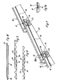
Wie insbesondere die Fig. 1 zeigt, ist der untere Bereich der wasserführenden Falzes 11 konisch ausgebildet. Der Querschnitt wird zum unteren traufseitigen Ende hin größer, da der äußere Seitensteg und der dieser Seite zugeordnete andere Randsteg entgegengesetzt auseinanderlaufen. Der Randsteg 18 des Deckfalzes 12 und der dieser Seite zugeordnete Randsteg laufen in etwa parallel zum Randsteg des wasserführenden Falzes 11. Dadurch ergeben sich zwischen den nebeneinander liegenden Dacheindeckungsplatten 10, in der Projektion gesehen, das Erscheinungsbild eines Daches auflockernde Dreiecke 21. Je nachdem, wann die besagten Stege schräg verlaufen, ergeben sich kleinere oder größere Dreiecke. Um das besonders deutlich zu machen, können die oberen Seiten mit Fasen versehen sein. Die unterschiedlichen Erscheinungsbilder aufgrund verschieden hoher Dreiecke 21 sind in den Fig. 4 bis 6 dargestellt.As shown in FIG. 1 in particular, the lower region of the water-carrying fold 11 is conical. The cross section becomes larger towards the lower eaves-side end, since the outer side web and the other edge web assigned to this side diverge in opposite directions. The
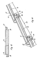
Die Fig. 7 zeigt eine erste Ausführung einer Dacheindeckung in einem Schnitt parallel zu den Sparren mit Dichtungsplatten 16, die verhältnismäßig dünn sind. Wie die Fig. 7 zeigt, ist bei dieser Ausführung die Dicke einer Dichtungsplatte 16 ein klein wenig geringer als die Wandstärke der Dacheindeckungsplatte im mittleren Bereich, d.h. in dem Bereich der frei von Stegen ist. Die obere, den Dacheindeckungsplatten 10 zugewandte Fläche der Sparren ist durch die Vollinie 22 gekennzeichnet. Die parallel und im Abstand zueinander und quer zu den Sparren verlaufenden Dachlatten sind durch die Bezugszeichen 23 gekennzeichnet. Die Fig. 7 zeigt, daß die Dichtungsplatten 16 parallel zu den äußeren Flächen der Dacheindeckungsplatten 10 verlaufen. Sofern die Dacheindeckungsplatten 10 gewellt oder sonstwie profiliert sind, verlaufen die Dichtungsplatten parallel und in Abstand zu den aus den Erhöhungen und Vertiefungen gebildeten Ebenen. Durch die sich überlappenden Querränder der Dacheindeckungsplatten 10 ergibt sich deshalb, daß die Dichtungsplatten 16 schräg zu den oberen Flächen der Sparren verlaufen. Bei einer gedachten Verlängerung der Dichtungsplatten 16 zum First hin ergibt sich ein kleiner spitzer Winkel von beispielsweise 5° . Wie die Figur zeigt, stützt der traufseitige Rand jeder Dichtungsplatte 16 auf der Auflagerfläche 15 der Dacheindeckungsplatte 10 ab. Das firstseitige Ende jeder Dichtungsplatte 16 liegt zwischen den quer zu den Längsseiten verlaufenden Randstegen 18 und der jeweiligen Dachlatte 23. Bei dieser Ausführung liegen die Dichtungsplatten zwischen den Dachlatten, wobei der firstseitige Rand die Dachlatte nicht überragt. Die Breite jeder Dichtungsplatte 10 kann der Deckbreite der Dacheindeckungsplatte 10 entsprechen, oder ganzzahliges Vielfaches davon sein. Auch die Breite der Auflagerfläche 15 entspricht der Deckbreite der Dacheindeckungsplatte 10. Die Dichtungsplatten 16 sind auf der Unterkonstruktion nicht befestigt, sondern werden ausschließlich durch das Gewicht der Dacheindeckungsplatten 10 festgeklemmt. Die Dichtungsplatten 16 können aus Papier oder Kunststoff gefertigt sein. Die Fig. 8 bis 10 zeigen drei bevorzugte Querschnittsformen. Der Querschnitt nach der Fig. 8 ist wie eine Wellpappe und besteht demzufolge aus zwei Trägerbahnen 24 und einer Verstärkungsbahn 25. Die Fig. 9 zeigt einen ähnlichen Querschnitt, wobei jedoch die Verstärkungsbahn 25 nicht wellenförmig sondern trapezförmig gefaltet ist. Durch diese Ausbildung der beiden Verstärkungsbahnen 25 wird das Widerstandsmoment gegen Biegung wesentlich erhöht. Die Breite der einzelnen Dichtungsplatten 16 können in zweckmäßiger Weise größer sein als die Deckbreiten der Dacheindeckungsplatten 10, so daß sie sich an den Längsrändern überlappen. Bei der Ausführung nach der Fig. 10 ist jede Dichtungsplatte 16 als massive Platte ausgebildet. In gleicher Weise wie bei den Dacheindeckungsplatten 10 sind an den Längsrändern sich im verlegten Zustand gegenseitig überlappende Überdeckungsstege 26,27 vorgesehen. Die Fig. 7 zeigt außerdem, daß der der Unterkonstruktion zugewandte, firstseitig Randbereich als Schrägfläche ausgebildet ist, damit dieser Randbereich vollflächig auf der Dachlatte 23 aufliegt. Die Ausführung nach der Fig. 11 unterscheidet sich von der nach der Fig. 7 durch Dichtungsplatten 16 größerer Dicke, die zwischen zwei und drei Zentimetern liegen kann. Die Dichtungsplatten 16 sind aus einem thermisch isolierenden Material gefertigt, beispielsweise aus einem geschäumten Kunststoff. Sie sind demzufolge Isolierplatten, die eine vollflächige Wärmedämmschicht bilden. Auch bei dieser Ausführung verlaufen die Dichtungsplatten 16 parallel zu der frei von Stegen gehaltenen wetterseitigen Fläche. Der Abstand der Auflagerfläche 15 zu den äußeren Flächen der Dacheindeckungsplatte 10 ist größer als bei der Ausführung nach der Fig. 7. Der der Unterkonstruktion zugewandte, firstseitige Randbereich jeder Dichtungsplatte 16 weist eine Aussparung 28 auf, die zur vollflächigen Auflage auf der Dachlatte 23 als eine entsprechend geneigte Schrägfläche ausgebildet ist. Die Fig. 12 zeigt die Dichtungsplatte 16 nach der Fig. 11 im Querschnitt. Die Dichtungsplatte 16 ist wiederum beidseitig mit Überdeckungsstegen 26,27 versehen. Zu der jeweils offenen Seite hin ist noch eine Nut 29 vorgesehen, deren äußere Begrenzung eine Schrägfläche ist, so daß die nebeneinandergereihten Dichtungsplatten aneinandergezogen werden.Fig. 7 shows a first embodiment of a roof covering in a section parallel to the rafters with sealing
Bei der Ausführung nach der Fig. 13 ist jede Dichtungsplatte 16 keilförmig ausgebildet, wobei die Dicke zum firstseitigen Rand hin abnimmt. Jede Dichtungsplatte 16 ist so gestaltet, daß die der Dacheindeckungsplatte 10 zugewandte äußere Fläche parallel und im Abstand zu der stegfreien Fläche der Dacheindeckungsplatte 10 liegt. Die untere, der Unterkonstruktion zugewandte Fläche verläuft parallel in einem geringen Abstand zur oberen Fläche 22 des Sparrens. Durch diese Ausführung wird eine bessere Wärmedämmung erzielt. Die traufseitige Stirnfläche jeder Dichtungsplatte 16 ist mit einer quer zu den Längsrändern sich erstreckenden Profilnut versehen, in die die Köpfe 14 oder Stege liegen. Außerdem bildet die angrenzende Dachlatte 23 ein Widerlager für die Dichtungsplatte 16. Sie stützt sich also nicht nur auf der Auflagerfläche 15 ab, sondern auch noch an der traufseitigen Fläche der jeweiligen Dachlatte 23. In der Fig. 14 ist der Querschnitt der Dichtungsplatte 16 gem. der Fig. 13 dargestellt. Danach sind die Längsränder entgegengesetzt stufenförmig ausgebildet, wobei die oberen Stufen die Überdeckungsstege 26,27 bilden, die wiederum mit jeweils einer Nut 29 versehen sind, deren äußere Begrenzung ebenfalls durch eine Schrägfläche gebildet ist.13, each sealing
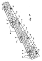
Bei den in den Fig. 15 bis 17 dargestellten Ausführungsbeispielen weist jede Dichtungsplatte 16 einen gegenüber der zugeordneten Dachlatte 23 in Richtung zum First vorstehenden Kragarm 30 auf. Diese Dichtungsplatte weist wiederum eine Aussparung 28 auf, um sie auf die Dachlatte 23 aufzuhängen. An der Wetterseite und in Richtung zum firstseitigen Ende versetzt weist der Kragarm 30 eine quer zu den Längsseiten verlaufenden Nut 31 auf, in die die Köpfe 14 der Dacheindeckungsplatten eingreifen. Auch bei dieser Ausführung weist die Dacheindeckungsplatte 10 am firstseitigen Rand die ebene Auflagerfläche 15 auf. Diese Ausführung bietet den Vorteil, daß sich die reihenweise verlegten Dichtungsplatten 16 überlappen, wodurch Kältebrücken vermieden werden. Durch die unterbrochene Linie 32 ist die Stellung des Kragarmes 30 im unbelasteten Zustand dargestellt. Bei Belastung durch die Dacheindeckungsplatten 10 wird der Kragarm in Richtung zur Unterkonstruktion gebogen. Durch diese Gestaltung werden die kontaktierenden Flächen durch die Rückstellkräfte aneinandergepreßt, so daß eine besondere Dichtwirkung erzielt wird.In the exemplary embodiments shown in FIGS. 15 to 17, each sealing
Die Ausführung nach der Fig. 16 unterscheidet sich im wesentlichen durch eine größere Dicke der Dichtungsplatten 16 sowie die stufenförmige Ausbildung des Kragarmes 30 mit einer entgegengesetzt abgestuften Ausbildung des traufseitigen Endes der Dichtungsplatten 16. Der Querschnitt der Dichtungsplatten nach der Fig. 15 entspricht dem Querschnitt nach der Fig. 12. Der Querschnitt der Dichtungsplatten nach der Fig. 16 entspricht dem in der Fig. 14 gezeichneten. Durch diese stufenförmige Ausbildung wird eine zusätzliche Dichtigkeit geschaffen, da es keine durchgehende Fuge gibt. Bei dem in der Fig. 17 dargestellten Ausführungsbeispiel ist jede Isolierpaltte 16 wiederum mit einem Kragarm 30 versehen. Der restliche Teil jeder Isolierplatte 16 überragt aber zwei durch drei Dachlatten 23 gebildete Felder. Dadurch findet eine Überlappung statt, so daß die aus den Dichtungsplatten 16 gebildete Wärmedämmlage im Sinne einer zweischichtigen Lage anzusehen ist. Auch hier stützt sich der traufseitige Rand auf der Auflagerfläche 15 der Dacheindeckungsplatte 10 ab. Jede Dacheindeckungsplatte 10 ist außerdem mit der Aussparung 28 sowie einer versetzt dazu verlaufenden Nut 31 für die Köpfe 14 versehen. Der Vorteil dieser Ausführung ist, daß die Dichtungsplatten 16 im Verband, d.h. gegeneinander versetzt verlegt werden können, so daß eine seitliche Verfalzung entfällt. Bei den Ausführungsbeispielen nach den Fig. 15 bis 17 verläuft die der Dacheindeckungsplatte 10 zugeordnete Fläche jeder Isolierplatte 16 parallel zum stegfreien Bereich der Dacheindeckungsplatte 10, während die der Unterkonstruktion zugewandte Fläche in einem spitzen Winkel zur oberen Fläche des Sparrens verläuft. Die Ausführung nach den Fig. 16 und 17 bietet den Vorteil einer größeren Dicke. Bei der Ausführung nach der Fig. 18 erstreckt sich jede Isolierplatte 16 wiederum über zwei von drei Dachlatten 23 begrenzte Felder. Bei dieser Ausführung fehlt jedoch der Kragarm. Dazu ist jedoch wiederum eine seitliche Verfalzung notwendig. Die Dichtungsplatten 16 werden auch bei dieser Ausführung im Verband verlegt. Die Querschnittsform entspricht der Fig. 14. Im Gegensatz zu den in den Fig. 17 und 18 dargestellten Ausführungen können auch mehr als zwei Felder abgedeckt werden. Die Stückzahl der Felder stimmt immer mit der Anzahl der einzelnen Lagen überein.16 differs essentially by a greater thickness of the sealing
Die Einzelheit nach der Fig. 7a unterscheidet sich von der Ausführung nach der Fig. 7 durch einen Dichtungsstreifen 33, der an der der Wetterseite abgewandten Seite am traufseitigen Rand der Dichtungsplatte 16 angeordnet ist und quer zu den Längsrändern verläuft. Dieser Dichtungsstreifen ist aus einem elastisch verformbaren Material, um fertigungstechnisch bedingte Höhenunterschiede der Auflagerflächen 15 auszugleichen.The detail according to FIG. 7a differs from the embodiment according to FIG. 7 by a sealing
Die Fig. 8 und 9 zeigen, daß die beiden Trägerbahnen 24 und die Verstärkungsbahn 25 gleich breit sind, wobei jedoch die beiden Trägerbahnen 24 gegenüber den Längsseiten der Verstärkungsbahn 25 nach außen um ein gleiches Maß versetzt sind, so daß sich im verlegten Zustand die Längsränder von zwei aneinanderliegenden Dichtungsplatten 15 überlappen und wobei die Trägerbahnen an der oberen und unteren Seite eine vollflächige Abdeckung bilden. In nicht dargestellter Weise können die Längsränder der Dichtungsplatten 15 mit einem Selbstklebestreifen oder mit einem Streifen aus einem Klebstoff versehen sein. Dadurch ist es möglich, die einzelnen Dichtungsplatten 15 an den Längsrändern miteinander zu verkleben. Sofern ein Klebstoff verwendet wird, ist es zweckmäßig, wenn die deckungsgleich liegenden Klebstoffstreifen ohne Anfeuchten miteinander verkleben. In den dargestellten Ausführungsbeispielen weist jede Dacheindeckungsplatte 10 zwei parallel und im Abstand zueinander verlaufende Auflagerflächen 15 auf. Es wird jedoch je nach Art der Dichtungsplatten 16 immer nur eine Auflagerfläche 15 verwendet. In nicht dargestellter Weise ist es jedoch möglich, daß auf die der Wetterseite abgewandt liegende Auflagerfläche sich der traufseitige Rand einer Isolierplatte und auf der der Wetterseite zugewandt liegenden Auflagerfläche der traufseitige Rand einer Dichtungsplatte abstützt. Eine solche Ausführung könnte als ein Doppelauflager bezeichnet werden. Die Fig. 1 zeigt noch, daß der Auflagerfläche 15 ein quer zu den Längsrändern verlaufender Anschlag 17a zugeordnet ist, gegen den die traufseitig Stirnkante der Dichtungsplatte 16 stoßen kann. Trotz dieses Anschlages kann das Wasser abfließen.8 and 9 show that the two
Die Figuren 19 und 20 zeigen im Längsschnitt zwei weitere Ausführungsformen der Köpfe der Dacheindeckungsplatten 10. Aus diesen Figuren ist deutlich zu erkennen, daß die Auflagerfläche 15 keine ebene Fläche ist, sondern daß sie erhabene Teilflächen hat, das heißt die erhabenen Teilflächen stehen zur Wetterseite hin vor. Wie auch zu erkennen ist, verspringt die Auflagerfläche 15 gegenüber den angrenzenden Außenflächen in Richtung zur Unterkonstruktion. Dadurch wird eine annähernd zur Dachfläche senkrecht stehende Fläche geschaffen, die im Sinne eines Anschlages 34 für die Dichtungsplatte 16 zu sehen ist. Die firstseitige Begrenzung der Auflagerfläche 15 wird durch einen quer zu den Längsrändern der Dacheindeckungsplatte 10 verlaufenden Steg 35 gebildet, der gegenüber der eigentlichen Auflagerfläche 15 zur Wetterseite hin vorsteht. Dieser Steg 35 ist im Querschnitt dreieckförmig ausgebildet, wobei der obere Rand in einem Radius verläuft. Bei der Ausführung nach der Figur 20 ist die Auflagerfläche 15 abgewinkelt, so daß die Höhe dieses Steges 35 geringer ist als bei der Ausführung nach der Figur 19. Außerdem ist der Kopf der Dacheindeckungsplatte 10 bei der Ausführung nach der Figur 20 so gestaltet, daß die zugeordnete Dichtungsplatte 16 im traufseitigen Stirnendbereich stufenförmig ausgebildet ist. Dadurch werden zwei Auflagerflächen geschaffen, die die Dichtigkeit erhöhen. Aus den Figuren geht deutlich hervor, daß sich die Dichtungsplatte 16 in den Steg 35 hineindrückt, bedingt durch das Gewicht der über der Dichtungsplatte 16 liegenden, nicht dargestellten Dacheindeckungsplatte. Durch dieses Eindrücken des Steges 35, der sich über die gesamte Breite der Dacheindeckungsplatte 10 erstreckt, wird die Dichtigkeit noch zusätzlich erhöht, da sie im Sinne einer Labyrinthdichtung zu sehen ist. Diese Art ist besonders vorteilhaft, da es bei aus Ton hergestellten Dacheindeckungsplatten beim Brennen zum Verzug kommt, so daß diese Dacheindeckungsplatten niemals genau planebene Flächen oder Kanten haben. Aus den Figuren ergibt sich, daß die Höhe des Anschlages 34 ein klein wenig geringer ist als die Dicke der Dichtungsplatte 16, so daß es zu dem besagten Eindrücken der Dichtungsplatte 16 bei einer Belastung kommen kann.Figures 19 and 20 show in longitudinal section two further embodiments of the heads of the
- 1010th
- DacheindeckungsplatteRoofing slab
- 1111
- wasserführender Falzwater-bearing fold
- 1212
- DeckfalzTop fold
- 1313
- DachlatteRoof batten
- 1414
- Kopfhead
- 1515
- AuflagerflächeBearing surface
- 1616
- DichtungsplatteSealing plate
- 1717th
- Steg, 17 a AnschlagBridge, 17 a stop
- 1818th
- RandstegEdge bridge
- 1919th
- VorkammerAntechamber
- 2020th
- BelüftungsöffnungVentilation opening
- 2121
- Dreiecktriangle
- 2222
- obere Flächetop surface
- 2323
- DachlatteRoof batten
- 2424th
- TrägerbahnCarrier web
- 2525th
- VerstärkungsbahnReinforcement track
- 2626
- ÜberdeckungsstegCover bridge
- 2727th
- ÜberdeckungsstegCover bridge
- 2828
- AussparungRecess
- 2929
- NutGroove
- 3030th
- KragarmCantilever
- 3131
- NutGroove
- 3232
- Linieline
- 3333
- Dichtungpoetry
- 3434
- Anschlagattack
- 3535
- Stegweb
Claims (13)
Applications Claiming Priority (2)
| Application Number | Priority Date | Filing Date | Title |
|---|---|---|---|
| DE4006772 | 1990-03-03 | ||
| DE4006772A DE4006772C2 (en) | 1990-03-03 | 1990-03-03 | Roof covering made of roof covering plates with overlapping longitudinal and transverse edges |
Publications (2)
| Publication Number | Publication Date |
|---|---|
| EP0445666A1 true EP0445666A1 (en) | 1991-09-11 |
| EP0445666B1 EP0445666B1 (en) | 1992-06-03 |
Family
ID=6401392
Family Applications (1)
| Application Number | Title | Priority Date | Filing Date |
|---|---|---|---|
| EP91103105A Expired - Lifetime EP0445666B1 (en) | 1990-03-03 | 1991-03-01 | Roof covering composed of roof tiles with overlapping longitudinal- and transversal edges |
Country Status (4)
| Country | Link |
|---|---|
| EP (1) | EP0445666B1 (en) |
| AT (1) | ATE76925T1 (en) |
| DE (2) | DE4006772C2 (en) |
| DK (1) | DK0445666T3 (en) |
Cited By (3)
| Publication number | Priority date | Publication date | Assignee | Title |
|---|---|---|---|---|
| NL1003191C2 (en) * | 1996-05-23 | 1997-11-25 | Ubbink Nederland Bv | Sloping slate roof |
| US8074417B2 (en) * | 2006-10-27 | 2011-12-13 | Exteria Building Products, Llc | Decorative wall covering with improved interlock system |
| EP3401461A1 (en) * | 2017-05-09 | 2018-11-14 | Erlus Aktiengesellschaft | Interlocking roof tile |
Families Citing this family (2)
| Publication number | Priority date | Publication date | Assignee | Title |
|---|---|---|---|---|
| DE10300963B4 (en) * | 2003-01-10 | 2016-09-29 | Erlus Aktiengesellschaft | Roof construction element with increasing water groove in cross-section |
| DE102006038731A1 (en) * | 2006-08-15 | 2008-02-21 | Oskar Fleck | Roof covering comprises roofing plate of base area till water groove, where roofing plate has even thickness with even surface, water groove at longitudinal sides, and covering side, and heat insulation is integrated in lower surface |
Citations (8)
| Publication number | Priority date | Publication date | Assignee | Title |
|---|---|---|---|---|
| DE1509106A1 (en) * | 1962-08-25 | 1969-05-22 | Werner Henning | Docking made of plastic or other material as a base for tile roofs |
| DE1509101A1 (en) * | 1964-09-05 | 1971-04-29 | Karl Fahr Jun | brick |
| FR2113451A5 (en) * | 1970-11-03 | 1972-06-23 | Ludowici Michael | |
| DE3334926A1 (en) * | 1983-09-27 | 1985-06-27 | CPM-Ceramic Patent Management Inc., Lehigh Acres, Fla. | Wall and roof covering element |
| DE3508631A1 (en) * | 1985-02-15 | 1986-08-21 | Helfrecht, Manfred, 8598 Waldershof | Heat-insulating element for beneath a roof |
| EP0256263A1 (en) * | 1986-07-11 | 1988-02-24 | Eugen Feil | Roofing structure covered with roof covering panels |
| DE3705281A1 (en) * | 1987-02-19 | 1988-09-01 | Eugen Feil | Roof element |
| EP0348822A1 (en) * | 1988-06-30 | 1990-01-03 | Heinz Wacker | Roof covering composed of roof tiles with overlapping longitudinal and transversal edges |
Family Cites Families (11)
| Publication number | Priority date | Publication date | Assignee | Title |
|---|---|---|---|---|
| DE248352C (en) * | ||||
| AT295101B (en) * | 1969-02-25 | 1971-12-27 | Walter Brunner | Component made up of two or more layers |
| DE2517419C2 (en) * | 1974-10-02 | 1986-06-12 | Thermodach Dachtechnik GmbH, 8598 Waldershof | Under roof |
| DE2745845A1 (en) * | 1977-10-12 | 1979-04-19 | Theodor Greis | Roof heat insulating panel - has length equalling rafter interval and has cut=out and beading in edge nearest eaves |
| DE7739995U1 (en) * | 1977-12-29 | 1978-07-06 | Traub, Tillo, 7151 Stangenbach | COVER FOR A ROOF INSULATION |
| DE2933554A1 (en) * | 1979-08-18 | 1981-03-26 | Dynamit Nobel Ag, 5210 Troisdorf | Steep roof tiling - with plastic heat insulation and skin elements |
| DE2944697A1 (en) * | 1979-11-06 | 1981-05-14 | Oskar 4354 Datteln Fleck | Panelled roof weatherproofing element - has bottom C=shaped groove formed by insulating panel and overlapping support panel |
| DE8224221U1 (en) * | 1982-08-27 | 1982-11-25 | Rütgerswerke AG, 6000 Frankfurt | THERMAL INSULATED SHINGLE ELEMENT |
| GB2131060B (en) * | 1982-11-24 | 1986-05-21 | Marley Roof Tile | Preventing penetration of water through tiled or slated pitched roofs |
| DE3822066A1 (en) * | 1988-06-30 | 1990-01-04 | Heinz Wacker | Roof for a building |
| DE3919511C1 (en) * | 1989-06-15 | 1990-09-13 | Eugen 7084 Westhausen De Feil |
-
1990
- 1990-03-03 DE DE4006772A patent/DE4006772C2/en not_active Expired - Fee Related
-
1991
- 1991-03-01 EP EP91103105A patent/EP0445666B1/en not_active Expired - Lifetime
- 1991-03-01 DE DE9191103105T patent/DE59100002D1/en not_active Expired - Lifetime
- 1991-03-01 AT AT91103105T patent/ATE76925T1/en not_active IP Right Cessation
- 1991-03-01 DK DK91103105.2T patent/DK0445666T3/en active
Patent Citations (8)
| Publication number | Priority date | Publication date | Assignee | Title |
|---|---|---|---|---|
| DE1509106A1 (en) * | 1962-08-25 | 1969-05-22 | Werner Henning | Docking made of plastic or other material as a base for tile roofs |
| DE1509101A1 (en) * | 1964-09-05 | 1971-04-29 | Karl Fahr Jun | brick |
| FR2113451A5 (en) * | 1970-11-03 | 1972-06-23 | Ludowici Michael | |
| DE3334926A1 (en) * | 1983-09-27 | 1985-06-27 | CPM-Ceramic Patent Management Inc., Lehigh Acres, Fla. | Wall and roof covering element |
| DE3508631A1 (en) * | 1985-02-15 | 1986-08-21 | Helfrecht, Manfred, 8598 Waldershof | Heat-insulating element for beneath a roof |
| EP0256263A1 (en) * | 1986-07-11 | 1988-02-24 | Eugen Feil | Roofing structure covered with roof covering panels |
| DE3705281A1 (en) * | 1987-02-19 | 1988-09-01 | Eugen Feil | Roof element |
| EP0348822A1 (en) * | 1988-06-30 | 1990-01-03 | Heinz Wacker | Roof covering composed of roof tiles with overlapping longitudinal and transversal edges |
Cited By (3)
| Publication number | Priority date | Publication date | Assignee | Title |
|---|---|---|---|---|
| NL1003191C2 (en) * | 1996-05-23 | 1997-11-25 | Ubbink Nederland Bv | Sloping slate roof |
| US8074417B2 (en) * | 2006-10-27 | 2011-12-13 | Exteria Building Products, Llc | Decorative wall covering with improved interlock system |
| EP3401461A1 (en) * | 2017-05-09 | 2018-11-14 | Erlus Aktiengesellschaft | Interlocking roof tile |
Also Published As
| Publication number | Publication date |
|---|---|
| EP0445666B1 (en) | 1992-06-03 |
| DE4006772A1 (en) | 1991-09-05 |
| DK0445666T3 (en) | 1992-09-14 |
| DE59100002D1 (en) | 1992-07-09 |
| ATE76925T1 (en) | 1992-06-15 |
| DE4006772C2 (en) | 1994-04-21 |
Similar Documents
| Publication | Publication Date | Title |
|---|---|---|
| EP0256263B1 (en) | Roofing structure covered with roof covering panels | |
| DE2842347C2 (en) | Thermal insulation panels that can be laid on rafters | |
| EP0445666B1 (en) | Roof covering composed of roof tiles with overlapping longitudinal- and transversal edges | |
| DE4000955C2 (en) | Light element for foamed polyurethane roof elements | |
| DE2102537A1 (en) | Plate-shaped component made of Harl foam plastic or the like. with fold-like edges for thermal insulation of roof and wall surfaces | |
| DE2349710A1 (en) | THERMAL INSULATED ROOF COVERING | |
| EP0601396B1 (en) | Drain web to be rolled-up | |
| DE3535560C2 (en) | ||
| DE10201528C1 (en) | Roof hip connector board, between the lower edge of a hip tile and the roof covering board, is a projection of the covering board surface with a wedge projection on the upper side towards the roof hip | |
| DE3634116A1 (en) | Sealing arrangement for structures | |
| DE4438331C2 (en) | Roof board | |
| DE1609986A1 (en) | Sub-roof for the insulation of roofs made of roof tiles or the like. | |
| DE1934295U (en) | INSULATION PANEL FOR THE INSULATION OF FLAT INCLINED ROOFS. | |
| DE3822066A1 (en) | Roof for a building | |
| DE3232449C2 (en) | Inclined ceiling | |
| DE19728980C2 (en) | Roof construction as a basic construction supporting a roof covering as well as supporting and insulating element | |
| EP0162953B1 (en) | Ridge covering | |
| DE2842778C2 (en) | Thermal insulation board made of rigid foam plastic | |
| EP0890683B1 (en) | Roof Structure | |
| DE3328092A1 (en) | Panel for insulating roofs, floors, wall surfaces or the like | |
| DE2239556C3 (en) | Edging for flat roofs or the like. | |
| DE7902687U1 (en) | INSULATION ELEMENT | |
| DE8536430U1 (en) | Profiled insulating plate with support film for corrugated boards | |
| DE4030710A1 (en) | Thermal insulation panels for sloping roof - incorporates tongue=and=groove joints with moisture drainage channels | |
| DE7216448U (en) | Coated dam plate |
Legal Events
| Date | Code | Title | Description |
|---|---|---|---|
| PUAI | Public reference made under article 153(3) epc to a published international application that has entered the european phase |
Free format text: ORIGINAL CODE: 0009012 |
|
| AK | Designated contracting states |
Kind code of ref document: A1 Designated state(s): AT BE CH DE DK FR GB IT LI NL SE |
|
| 17P | Request for examination filed |
Effective date: 19910719 |
|
| 17Q | First examination report despatched |
Effective date: 19911112 |
|
| GRAA | (expected) grant |
Free format text: ORIGINAL CODE: 0009210 |
|
| ITF | It: translation for a ep patent filed |
Owner name: STUDIO INGG. FISCHETTI & WEBER |
|
| AK | Designated contracting states |
Kind code of ref document: B1 Designated state(s): AT BE CH DE DK FR GB IT LI NL SE |
|
| REF | Corresponds to: |
Ref document number: 76925 Country of ref document: AT Date of ref document: 19920615 Kind code of ref document: T |
|
| GBT | Gb: translation of ep patent filed (gb section 77(6)(a)/1977) | ||
| REF | Corresponds to: |
Ref document number: 59100002 Country of ref document: DE Date of ref document: 19920709 |
|
| ET | Fr: translation filed | ||
| REG | Reference to a national code |
Ref country code: DK Ref legal event code: T3 |
|
| PLBE | No opposition filed within time limit |
Free format text: ORIGINAL CODE: 0009261 |
|
| STAA | Information on the status of an ep patent application or granted ep patent |
Free format text: STATUS: NO OPPOSITION FILED WITHIN TIME LIMIT |
|
| 26N | No opposition filed | ||
| EAL | Se: european patent in force in sweden |
Ref document number: 91103105.2 |
|
| PGFP | Annual fee paid to national office [announced via postgrant information from national office to epo] |
Ref country code: GB Payment date: 19990316 Year of fee payment: 9 |
|
| PGFP | Annual fee paid to national office [announced via postgrant information from national office to epo] |
Ref country code: SE Payment date: 19990322 Year of fee payment: 9 |
|
| PGFP | Annual fee paid to national office [announced via postgrant information from national office to epo] |
Ref country code: FR Payment date: 19990329 Year of fee payment: 9 |
|
| PGFP | Annual fee paid to national office [announced via postgrant information from national office to epo] |
Ref country code: DK Payment date: 19990330 Year of fee payment: 9 Ref country code: CH Payment date: 19990330 Year of fee payment: 9 Ref country code: AT Payment date: 19990330 Year of fee payment: 9 |
|
| PGFP | Annual fee paid to national office [announced via postgrant information from national office to epo] |
Ref country code: NL Payment date: 19990331 Year of fee payment: 9 |
|
| PGFP | Annual fee paid to national office [announced via postgrant information from national office to epo] |
Ref country code: BE Payment date: 19990414 Year of fee payment: 9 |
|
| PG25 | Lapsed in a contracting state [announced via postgrant information from national office to epo] |
Ref country code: GB Free format text: LAPSE BECAUSE OF NON-PAYMENT OF DUE FEES Effective date: 20000301 Ref country code: DK Free format text: LAPSE BECAUSE OF NON-PAYMENT OF DUE FEES Effective date: 20000301 Ref country code: AT Free format text: LAPSE BECAUSE OF NON-PAYMENT OF DUE FEES Effective date: 20000301 |
|
| PG25 | Lapsed in a contracting state [announced via postgrant information from national office to epo] |
Ref country code: SE Free format text: LAPSE BECAUSE OF NON-PAYMENT OF DUE FEES Effective date: 20000302 |
|
| PG25 | Lapsed in a contracting state [announced via postgrant information from national office to epo] |
Ref country code: LI Free format text: LAPSE BECAUSE OF NON-PAYMENT OF DUE FEES Effective date: 20000331 Ref country code: CH Free format text: LAPSE BECAUSE OF NON-PAYMENT OF DUE FEES Effective date: 20000331 Ref country code: BE Free format text: LAPSE BECAUSE OF NON-PAYMENT OF DUE FEES Effective date: 20000331 |
|
| BERE | Be: lapsed |
Owner name: WACKER HEINZ Effective date: 20000331 |
|
| PG25 | Lapsed in a contracting state [announced via postgrant information from national office to epo] |
Ref country code: NL Free format text: LAPSE BECAUSE OF NON-PAYMENT OF DUE FEES Effective date: 20001001 |
|
| GBPC | Gb: european patent ceased through non-payment of renewal fee |
Effective date: 20000301 |
|
| EUG | Se: european patent has lapsed |
Ref document number: 91103105.2 |
|
| REG | Reference to a national code |
Ref country code: CH Ref legal event code: PL |
|
| PG25 | Lapsed in a contracting state [announced via postgrant information from national office to epo] |
Ref country code: FR Free format text: LAPSE BECAUSE OF NON-PAYMENT OF DUE FEES Effective date: 20001130 |
|
| NLV4 | Nl: lapsed or anulled due to non-payment of the annual fee |
Effective date: 20001001 |
|
| REG | Reference to a national code |
Ref country code: DK Ref legal event code: EBP |
|
| REG | Reference to a national code |
Ref country code: FR Ref legal event code: ST |
|
| PGFP | Annual fee paid to national office [announced via postgrant information from national office to epo] |
Ref country code: DE Payment date: 20010319 Year of fee payment: 11 |
|
| PG25 | Lapsed in a contracting state [announced via postgrant information from national office to epo] |
Ref country code: DE Free format text: LAPSE BECAUSE OF NON-PAYMENT OF DUE FEES Effective date: 20021001 |
|
| PG25 | Lapsed in a contracting state [announced via postgrant information from national office to epo] |
Ref country code: IT Free format text: LAPSE BECAUSE OF NON-PAYMENT OF DUE FEES;WARNING: LAPSES OF ITALIAN PATENTS WITH EFFECTIVE DATE BEFORE 2007 MAY HAVE OCCURRED AT ANY TIME BEFORE 2007. THE CORRECT EFFECTIVE DATE MAY BE DIFFERENT FROM THE ONE RECORDED. Effective date: 20050301 |