EP0445203B1 - Füllkörper in einem oder für einen behälter - Google Patents
Füllkörper in einem oder für einen behälter Download PDFInfo
- Publication number
- EP0445203B1 EP0445203B1 EP19900900235 EP90900235A EP0445203B1 EP 0445203 B1 EP0445203 B1 EP 0445203B1 EP 19900900235 EP19900900235 EP 19900900235 EP 90900235 A EP90900235 A EP 90900235A EP 0445203 B1 EP0445203 B1 EP 0445203B1
- Authority
- EP
- European Patent Office
- Prior art keywords
- packing
- adjacent
- insert
- vessel
- disposed
- Prior art date
- Legal status (The legal status is an assumption and is not a legal conclusion. Google has not performed a legal analysis and makes no representation as to the accuracy of the status listed.)
- Expired - Lifetime
Links
- 238000012856 packing Methods 0.000 title claims abstract description 78
- 239000012530 fluid Substances 0.000 claims abstract description 34
- 230000002093 peripheral effect Effects 0.000 claims description 13
- 239000000463 material Substances 0.000 claims description 11
- 238000000034 method Methods 0.000 claims description 9
- 238000004519 manufacturing process Methods 0.000 claims description 7
- 230000001419 dependent effect Effects 0.000 claims 1
- 239000007788 liquid Substances 0.000 description 11
- 239000007787 solid Substances 0.000 description 7
- 238000009826 distribution Methods 0.000 description 5
- 239000007789 gas Substances 0.000 description 5
- 238000000926 separation method Methods 0.000 description 4
- XLYOFNOQVPJJNP-UHFFFAOYSA-N water Substances O XLYOFNOQVPJJNP-UHFFFAOYSA-N 0.000 description 4
- 230000001154 acute effect Effects 0.000 description 2
- 239000003054 catalyst Substances 0.000 description 2
- 238000001816 cooling Methods 0.000 description 2
- 239000006185 dispersion Substances 0.000 description 2
- 238000001035 drying Methods 0.000 description 2
- 238000011835 investigation Methods 0.000 description 2
- 230000002829 reductive effect Effects 0.000 description 2
- 238000001223 reverse osmosis Methods 0.000 description 2
- 239000002904 solvent Substances 0.000 description 2
- 239000000126 substance Substances 0.000 description 2
- 238000012546 transfer Methods 0.000 description 2
- 238000009736 wetting Methods 0.000 description 2
- RNFJDJUURJAICM-UHFFFAOYSA-N 2,2,4,4,6,6-hexaphenoxy-1,3,5-triaza-2$l^{5},4$l^{5},6$l^{5}-triphosphacyclohexa-1,3,5-triene Chemical compound N=1P(OC=2C=CC=CC=2)(OC=2C=CC=CC=2)=NP(OC=2C=CC=CC=2)(OC=2C=CC=CC=2)=NP=1(OC=1C=CC=CC=1)OC1=CC=CC=C1 RNFJDJUURJAICM-UHFFFAOYSA-N 0.000 description 1
- RYGMFSIKBFXOCR-UHFFFAOYSA-N Copper Chemical compound [Cu] RYGMFSIKBFXOCR-UHFFFAOYSA-N 0.000 description 1
- 238000010521 absorption reaction Methods 0.000 description 1
- 230000002411 adverse Effects 0.000 description 1
- 230000000712 assembly Effects 0.000 description 1
- 238000000429 assembly Methods 0.000 description 1
- 230000031018 biological processes and functions Effects 0.000 description 1
- 238000006243 chemical reaction Methods 0.000 description 1
- 238000004587 chromatography analysis Methods 0.000 description 1
- 238000004581 coalescence Methods 0.000 description 1
- 238000002485 combustion reaction Methods 0.000 description 1
- 239000002131 composite material Substances 0.000 description 1
- 230000006835 compression Effects 0.000 description 1
- 238000007906 compression Methods 0.000 description 1
- 238000009833 condensation Methods 0.000 description 1
- 230000005494 condensation Effects 0.000 description 1
- 238000009792 diffusion process Methods 0.000 description 1
- 238000004821 distillation Methods 0.000 description 1
- 230000000694 effects Effects 0.000 description 1
- 238000000605 extraction Methods 0.000 description 1
- 239000003063 flame retardant Substances 0.000 description 1
- 238000010438 heat treatment Methods 0.000 description 1
- 230000000670 limiting effect Effects 0.000 description 1
- 230000014759 maintenance of location Effects 0.000 description 1
- 239000002184 metal Substances 0.000 description 1
- 229910052751 metal Inorganic materials 0.000 description 1
- 238000002156 mixing Methods 0.000 description 1
- 239000000203 mixture Substances 0.000 description 1
- 238000012986 modification Methods 0.000 description 1
- 230000004048 modification Effects 0.000 description 1
- 230000010355 oscillation Effects 0.000 description 1
- 230000036961 partial effect Effects 0.000 description 1
- 229920003023 plastic Polymers 0.000 description 1
- 239000004033 plastic Substances 0.000 description 1
- 238000012545 processing Methods 0.000 description 1
- 238000011084 recovery Methods 0.000 description 1
- 239000002356 single layer Substances 0.000 description 1
- 238000001179 sorption measurement Methods 0.000 description 1
- 238000000108 ultra-filtration Methods 0.000 description 1
Images



Classifications
-
- B—PERFORMING OPERATIONS; TRANSPORTING
- B01—PHYSICAL OR CHEMICAL PROCESSES OR APPARATUS IN GENERAL
- B01J—CHEMICAL OR PHYSICAL PROCESSES, e.g. CATALYSIS OR COLLOID CHEMISTRY; THEIR RELEVANT APPARATUS
- B01J19/00—Chemical, physical or physico-chemical processes in general; Their relevant apparatus
- B01J19/32—Packing elements in the form of grids or built-up elements for forming a unit or module inside the apparatus for mass or heat transfer
-
- F—MECHANICAL ENGINEERING; LIGHTING; HEATING; WEAPONS; BLASTING
- F28—HEAT EXCHANGE IN GENERAL
- F28F—DETAILS OF HEAT-EXCHANGE AND HEAT-TRANSFER APPARATUS, OF GENERAL APPLICATION
- F28F13/00—Arrangements for modifying heat-transfer, e.g. increasing, decreasing
-
- B—PERFORMING OPERATIONS; TRANSPORTING
- B01—PHYSICAL OR CHEMICAL PROCESSES OR APPARATUS IN GENERAL
- B01J—CHEMICAL OR PHYSICAL PROCESSES, e.g. CATALYSIS OR COLLOID CHEMISTRY; THEIR RELEVANT APPARATUS
- B01J2219/00—Chemical, physical or physico-chemical processes in general; Their relevant apparatus
- B01J2219/32—Details relating to packing elements in the form of grids or built-up elements for forming a unit of module inside the apparatus for mass or heat transfer
- B01J2219/322—Basic shape of the elements
- B01J2219/32279—Tubes or cylinders
-
- B—PERFORMING OPERATIONS; TRANSPORTING
- B01—PHYSICAL OR CHEMICAL PROCESSES OR APPARATUS IN GENERAL
- B01J—CHEMICAL OR PHYSICAL PROCESSES, e.g. CATALYSIS OR COLLOID CHEMISTRY; THEIR RELEVANT APPARATUS
- B01J2219/00—Chemical, physical or physico-chemical processes in general; Their relevant apparatus
- B01J2219/32—Details relating to packing elements in the form of grids or built-up elements for forming a unit of module inside the apparatus for mass or heat transfer
- B01J2219/322—Basic shape of the elements
- B01J2219/32282—Rods or bars
-
- B—PERFORMING OPERATIONS; TRANSPORTING
- B01—PHYSICAL OR CHEMICAL PROCESSES OR APPARATUS IN GENERAL
- B01J—CHEMICAL OR PHYSICAL PROCESSES, e.g. CATALYSIS OR COLLOID CHEMISTRY; THEIR RELEVANT APPARATUS
- B01J2219/00—Chemical, physical or physico-chemical processes in general; Their relevant apparatus
- B01J2219/32—Details relating to packing elements in the form of grids or built-up elements for forming a unit of module inside the apparatus for mass or heat transfer
- B01J2219/324—Composition or microstructure of the elements
- B01J2219/32466—Composition or microstructure of the elements comprising catalytically active material
-
- Y—GENERAL TAGGING OF NEW TECHNOLOGICAL DEVELOPMENTS; GENERAL TAGGING OF CROSS-SECTIONAL TECHNOLOGIES SPANNING OVER SEVERAL SECTIONS OF THE IPC; TECHNICAL SUBJECTS COVERED BY FORMER USPC CROSS-REFERENCE ART COLLECTIONS [XRACs] AND DIGESTS
- Y10—TECHNICAL SUBJECTS COVERED BY FORMER USPC
- Y10S—TECHNICAL SUBJECTS COVERED BY FORMER USPC CROSS-REFERENCE ART COLLECTIONS [XRACs] AND DIGESTS
- Y10S261/00—Gas and liquid contact apparatus
- Y10S261/72—Packing elements
Definitions
- This invention relates to a packing in or for a vessel to contact fluid therein.
- the vessel may be a heat exchange tube for heating or cooling of fluid flowing through the tube and in this case packing improves the efficiency of heat transfer.
- the vessel may be a fluid treatment apparatus such as a fluid-fluid or fluid-solid or fluid-fluid-solid contacting, de-entraining and/or coalescing, or extraction or liquid-vapour distillation or liquid-gas absorption or other contacting, de-entraining, physical and/or chemical reactor vessel, tube, column, tower or the like.
- packing is provided to improve, for example, one or more of the following; separation, distribution or dispersion of fluids, mixing, reacting, separation, distribution or dispersion of a fluid, or fluids and a solid, increasing the rate of diffusion or permeation in tubes used for reverse osmosis and permeation de-humidification, coalescence, drying and the like.
- GB-PS-483642 discloses a vessel having a single element of packing disposed therein wherein the vessel is a radiator tube for an internal combustion engine and the packing is provided to improve the efficiency of cooling of the fluid in the radiator tube.
- the packing has very low efficiency due to a low surface area per unit volume and the packing makes poor contact with the walls of the vessel giving high voidage, maldistribution of the fluid, low mass and heat transfer.
- GB-PS-1570530 discloses a vessel having a packing disposed therein wherein the vessel comprises a fluid-fluid or fluid-solid contacting, deentrainment or reaction apparatus and the packing comprises a plurality of short articles distributed randomly within the apparatus, each article comprising two elongate members twisted together to form a central core and having trapped therebetween a plurality of convolutions which collectively extend in helical fashion about the central core.
- This random spring packing because of the irregularities of the alignment of the packing elements, gives maldistribution of the fluids flowing over the packing. This maldistribution and low efficiency increases as the diameter of the vessel is increased.
- GB-2097910 discloses a vessel having a packing comprising a plurality of relatively short inserts, the inserts having a length to diameter ratio not greater than 2:1 and arranged in a relatively large diameter vessel, for example, of 2 metre diameter.
- the inserts comprising a core having a plurality of loops disposed longitudinally therealong and angularly thereabout and are inclined to the longitudinal axis so that there is no intermeshing of the loops of adjacent side by side inserts with consequent high voidage between adjacent inserts, maldistribution of flow and the usual resultant shortcomings.
- US-2,332,110 discloses a vessel having a packing disclosed therein, wherein the vessel comprises a fractionating column.
- the packing comprises an assembly including a plurality of units, each unit consisting of a wire coiled to form a series of substantially similar loops, the loops forming areas substantially transverse to the path of said flow, the units being symmetrically disposed so that they form a generally circular composite structure with an open region in the centre thereof.
- the column has a plurality of such packing assemblies disposed therein in side by side relationship and with the part circumferentially extending portions of the loops of adjacent side by side units being separated by wire mesh enclosures which maintain each assembly intact. This packing therefore has low efficiency due to the low surface area per unit volume of packing and the relatively high voidage giving maldistribution of the fluid.
- An object of the present invention is to provide a vessel having a packing disposed therein thereby the above mentioned disadvantages are overcome or are reduced.
- the packing comprises a plurality of insert units, each insert unit comprising an elongate core having a plurality of transversely extending elements disposed at different longitudinal positions along the core and at different angular orientations about the core, wherein the insert units are disposed in side by side relationship in a regular manner with the core of each unit being disposed externally of each adjacent unit and at least one transversely extending element of each unit is interstitially disposed relative to transversely extending elements of an adjacent unit.
- a radially outermost portion of each transverse element may lie in close proximity to a first individual enveloping conceptual surface and the cross-sectional area between adjacent individual conceptual surfaces of adjacent insert units at least at one position longitudinally of the plurality of insert units is no greater than the maximum cross-sectional area within an individual conceptual surface of an insert unit between two adjacent transversely extending elements thereof on any cross-section longitudinally of the plurality of units.
- Said at least one transversely extending element may be disposed in an interstice between radially adjacent, or longitudinally adjacent, or radially and longitudinally adjacent transverse elements of an adjacent unit.
- the transverse elements may be disposed so that laterally rectilinearly lines as herein defined, extending from the core to a part of each transverse element most distant from the core, are disposed at different longitudinal positions along the core and different angular orientations around the core.
- Said lines may lie in a helical surface centred on the core.
- Each transverse element may comprise a loop of filamentary material and each loop may be generally circular.
- Each loop may comprise at least one turn of a helical coil.
- the core may comprise two elongate elements twisted together and a part of each of said loops being held between the twisted together elements.
- the core element and/or loops may be made of multifilament material or alternatively of single filament material and may be made, for example, of metal wire.
- the core elements and/or the transverse element may be made from material of any suitable cross-section material including non-circular cross-sectional filament.
- the transverse element may be made of material which is of zig-zag configuration, the oscillations lying in a surface which extends longitudinally of the insert unit.
- the core may comprise two elongate elements twisted together, each transverse element comprising a loop comprising at least one turn of a helical coil and a part of each of said loops being held between the twisted together elements.
- the elements may be disposed so that, over the length of the vessel there is no or substantially no rectilinear flow path for fluid.
- the insert units are disposed so that said surfaces overlap without any gap between adjacent conceptual surfaces.
- Lines intersecting laterally rectilinear lines of each loop at right angles passing through the sides of the loop may be rectilinear and substantially parallel to a diametrical plane of the core.
- Each insert unit may comprise a discrete insert.
- each insert unit may comprise part of a single insert which is formed so that said parts are disposed in said side-by-side relationship.
- said insert may be formed to a generally spiral shape so that adjacent turns of the spiral provide said insert units disposed in said side-by-side relationship.
- said inserts may be formed to a helical shape so that adjacent turns of the helix provide said insert units disposed in said side-by-side relationship.
- said insert may be formed to a generally sinuous shape so that adjacent runs of the sinuous shape provide said units disposed in said side-by-side relationship.
- Each insert unit may have a length to diameter ratio of at least 2:1, preferably at least 4:1.
- a packing according to the present invention may be disposed in a vessel to contact, in use, fluid therein.
- the transverse elements at a peripheral surface of the packing may be deformed relative to the shape of the transverse elements at positions spaced from the peripheral surface.
- the transverse elements at a peripheral surface of the packing may be displaced relative to the shape of the transverse elements at positions spaced from the peripheral surface.
- the transverse elements adjacent a wall of the vessel may be arranged to conform to the shape of the wall of the vessel.
- each transverse element of an insert unit may lie on a conceptual surface and the transverse elements adjacent a wall of the vessel may be arranged so as to conform to the shape of the wall of the vessel without a gap between the conceptual enveloping surfaces and the wall and without any rectilinear flow path adjacent said wall.
- a method of making a packing for placement in a vessel to contact fluid therein comprising taking an array comprising a plurality of insert units, each insert unit comprising, an elongate core having a plurality of transversely extending elements disposed at different longitudinal positions along the core and at different angular orientations about the core, wherein the insert units are disposed in side-by-side relation with the core of each unit disposed externally of each adjacent unit and wherein a portion of each transversely extending element adjacent a peripheral surface of the array lies in close proximity to a first conceptual overall enveloping surface and wherein the method comprises the step of acting on the transversely extending elements adjacent said peripheral surface to cause a portion thereof to lie in close proximity to a second conceptual overall enveloping surface of different cross-sectional area than said first conceptual overall enveloping surface and to cause at least one transversely extending element of a unit to be interstitially disposed relative to transversely extending elements of an adjacent unit.
- Said method may include the step of acting on a plurality of insert units by passing them into tapered guide parts of an entry portion of a tool and withdrawing the packing from an output tube of the tool.
- a vessel comprising an elongate tubular portion having disposed therein a packing to contact fluid therein wherein the packing is made according to the second aspect of the invention, the second conceptual overall enveloping surface having a cross-sectional configuration equal or substantially equal to that of the tubular portion so that the portion of each of said transversely extending elements in close proximity to said tubular portion is a greater proportion thereof than was in close proximity to the first conceptual surface.
- laterally rectilinear we mean that a line which is rectilinear when viewed in a direction normal to a surface containing the loop
- longitudinally rectilinear we mean that the line is rectilinear when viewed along a line, hereinafter referred to as a direction line, intersecting said line at right-angles and intersecting opposite sides of the loop
- longitudinally curved we mean that the line is curved when viewed along said direction line.
- close proximity we mean that the distance between an element and the surface lies in the range from zero and the lesser of the thickness of the element and 2mm and preferably 1mm.
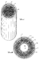
- FIG 1 shows a reactor vessel 10 having a packing 11 disposed therein.
- the vessel may be of other configuration, for example, the vessel may be a reactor with a central tube 10 a providing a port for control instrumentation such as thermo-couples as shown in Figure 1 a .
- the packing 11 comprises insert units disposed within the vessel in a regular manner in side by side relationship. Each insert unit comprises a discrete insert 12 which extends throughout the full length of the vessel.
- a plurality of inserts may be disposed longitudinally along the vessel, as well as side by side.
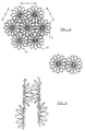
- Each insert 12 is made as shown in Figure 2 by taking a core 13, comprising a pair of spaced parallel core elements 13 a , 13 b , and disposing one element 13 a externally and the other element 13 b internally of the convolutions of a helical wire coil 14.
- the core elements are then twisted together so that the convolutions of the coil are trapped between the two wound together core elements and are caused to extend in a generally helical configuration about the core so that a medial line 15 of each loop 16 thus formed extending from the core to a part of the respective loop 16 at the greatest distance from the core are disposed at different longitudinal positions along the core and different angular orientations around the core, so that each line lies in a helical surface centred on the core as shown in Figure 3.
- the line 15 is laterally and longitudinally rectilinear as herein defined.
- the core element and the wire coil 14 are made of monofilament wire, but, if desired, any one or more of these components may be made of multifilament material.
- any one or more thereof may be of non-circular configuration, such as strip shape.
- any one or more of these components may be made of any other suitable material including, for example a synthetic plastics material.
- the inserts 12, described above are introduced into the vessel 10. If desired, the plurality of inserts may be assembled together in side by side relationship as hereafter to be described prior to introduction into the vessel and then introduced into the vessel 10 as a single assembly or a plurality of inserts may be assembled together as they are introduced into the vessel 10.
- tie members may be provided to hold the inserts in the assembly until the assembly has been introduced into the vessel.
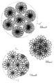
- Figure 4 is a diagrammatic illustration of an assembly where there are 12 loops for each turn of the helix and Figure 4 shows only the loops of a single turn of each helix.
- the distance d between the axes of adjacent inserts is preferably constant throughout the assembly and are shown only for same of the inserts for clarity.
- the distance d is chosen so that loops of adjacent units are intersticially disposed, as illustrated diagrammatically in Figure 5, and a part of at least some of the loops of each insert overlaps at least one loop of an adjacent insert, such that, as shown in Figure 4, there is no portion of the cross-section which is not overlapped, thereby ensuring, over the length of the vessel, that there is no rectilinear through path for fluid bearing in mind that in respect of each insert the helical disposition of the loops ensures that there is no rectilinear flow path for fluid within an insert whilst the above mentioned overlapping ensures that there is no rectilinear flow path for fluid between inserts.
- each insert has a conceptual enveloping surface, on which the radially outermost part of each loop lies.
- each enveloping surface there is no rectilinear through path because the projection of the loops on an end transverse surface obturates, preferably completely, that surface.
- the loops have been described as being of the shape illustrated in Figure 3, they may be non-circular or part-circular and lie in a plane perpendicular to the core.
- the loops 16, which lie in close proximity to a first conceptual enveloping surface S1 of diameter d1 are acted upon to cause a portion thereof to lie in close proximity to a second conceptual enveloping surface S2 of smaller cross-section than the first cross-sectional surface, so that the portion in close proximity to said second conceptual surface is a greater proportion of the loop perimeter than that in close proximity to the first conceptual surface.
- Such a step of thus acting upon the loops 16 may be performed by acting upon the loops with dies 17 having a recess 18 therein, as shown in Figure 7, which together define a cylindrical cavity the surface 19 of which lies in the above mentioned second conceptual surface.
- the loops 16 with the dies 17 By acting upon the loops 16 with the dies 17 by bringing the dies 17 together the loops are deformed from the configuration they have when in contact with the first conceptual surface S1, i.e. generally circular, to a non-circular configuration as shown in Figures 7 and 8, where a greater proportion of the loop diameter is in close proximity to the second enveloping surface S2 of diameter d2 smaller than diameter d1 of the first surface S1.
- the loops may be of other shape and configuration, for example, they may be long and narrow; for example, they may be greatly elongated ellipses or ovals and the ratio of the minor axis to the major axis may lie in the range 1:1 to 6:1.
- the lines 15 remain in the same orientation as is shown in Figure 3 although they are shorter, as shown at 15' in Figure 7.
- the inserts may have transverse elements in the form of single members which may be of any desired cross-sectional shape, for example, cylindrical or regular parallelepiped shape but in all cases the transverse elements of adjacent inserts overlap to the extent that there are no unobturated paths through the vessel with the possible exception of passageways partially defined by a wall of the vessel.
- each insert described above lies in a conceptual enveloping surface which may be of circular cross-section. These surfaces are arranged to overlap without gaps therebetween as described above.
- the axes of adjacent inserts may be positioned so that their separation is substantially equal to the radial distances from the respective cores to the radially outermost portion of the transversely extending elements, so that each element of one insert abuts or substantially abuts the core of an adjacent insert.
- the coils of the adjacent inserts totally overlap, thereby increasing the obturation to a rectilinear path through the assembly.
- obturations do not necessarily occur and in general will not occur, because of angularly and longitudinally adjacent transverse elements of an insert or of adjacent inserts overlapping sequentially.
- an angular position adjacent a given transverse element may not be obturated for a plurality of helical turns but nevertheless, taking the assembly as a whole there will be an obturation to rectilinear flow at some position along the length of the assembly, either by virtue of the projection, on an end transverse plane of the assembly, of all the components of an insert overlapping to provide obturation within the projected profile of an insert and by virtue of all the projected profiles of the inserts themselves overlapping, so as to avoid any gaps between inserts, or by virtue of the transverse elements of adjacent inserts combining together to provide an overlapped projected profile.
- the assembly may be acted upon, as described hereinbefore with regard to individual inserts, by radially moving dies similar to the dies 17 shown in Figure 7 so as to cause those transverse elements of the assembly of inserts which are to contact the wall of the vessel to be deformed so that the external surface of the insert conforms to the shape of the die.
- the lines 15 of the transverse elements which contact the wall of the die remain in the same orientation as prior to being acted upon by the die but are shortened so as to be similar to the lines 15' in Figure 7.
- the assembly may be acted upon by virtue of being passed longitudinally through a die so as to cause those transverse elements of the assembly of inserts which are to contact the wall of the vessel to be displaced so that the external surface of the insert conforms to the shape of the die.
- the lines 15 of the transverse elements which contact the wall of the die are caused to be inclined to the longitudinal axis of the assembly, although remaining of the same length.
- the external surface may be formed to a circular shape so as to eliminate any rectilinear passages within the vessel at the boundary with the vessel wall.
- the loops may be caused to lie in a longitudinally curved loop surface in which lines normal to said lateral rectilinear lines and intersecting opposite sides of the loop are rectilinear, but said line 15 is longitudinally curved.
- the loops may be both deformed as described above and be caused to lie in an inclined loop surface as described above or in a longitudinally curved loop surface as described above.
- the entry portion 32 has a guide part 33 and is of tapered configuration so that as inserts are passed through the tool their loops 16 are caused to intermesh insterstitially and the loops 16 which contact an internal surface 34 of the output tube 31 are displaced rearwardly as shown in Figure 11 so as to cause the loops to conform to the configuration of the surface 34 without gaps therebetween and hence form a configuration in the vessel as shown in the right-hand side of Figure 10.
- the packing shown in the left-hand side of Figure 10 is in itself 99.0% efficient in the removal of liquid but in the left-hand side of Figure 10 approximately by 20% of the liquid passes through the voids without being de-entrained. Since the packing operates at 99.0% efficiency with the packing operating at 99.0% efficiency 79.3 parts of liquid are removed to give an overall efficiency of 79.3%. In the case shown in the right-hand side of Figure 10 where there is no open free paths between the elements then 99.0 parts of the liquid are removed to give an overall efficiency of 99.0%.
- the assembly may be of any desired cross-sectional configuration, for example it may be of annular shape having a cylindrical or generally cylindrical external surface and a cylindrical or generally cylindrical internal passageway, the vessel itself being similarly shaped so that an external wall of the vessel surrounds the external cylindrical shape of the assembly whilst an internal wall of the vessel surrounds the internal passageway of the assembly.
- the shape of the internal passageway may be formed to desired configuration by acting upon the assembly with a mandrel or plug die or the like.
- transverse elements of adjacent insert units have been interstitially disposed so as to provide a maximum amount of material within a packing, that is within a conceptual overall enveloping surface with which a portion of each transversely extending element adjacent a peripheral surface of an array of insert units lies in close proximity, such as a surface E1 or E2 which is co-extensive with the wall of the central tube 10 a and the external wall 10 b of Figure 1 a , if desired alternate means can be provided.
- an array of inserts can be initially disposed as shown in Figure 6 so that portions of inserts adjacent the periphery lie in close proximity to a conceptual enveloping surface illustrated in dotted line at E' in Figure 6 and then such transversely extending members are acted upon to change the shape of the surface E' so as to reduce the cross-sectional area of the array by being acted upon either by drawing the array through a tool 30 such as shown in Figure 11, or by acting upon it with radially movable split dies as described hereinbefore to cause the transversely extending elements which contact the surface E' to cause a portion thereof to lie in close proximity to a second conceptual enveloping surface of smaller cross-section than the first conceptual surface either by being deformed from a first configuration which they have when they are in close proximity to the first surface to a second configuration which they have when in close proximity to the second surface as a result of being acted upon by split radially movable dies, or by being caused to be moved from lying in a loop surface which is substantially parallel to
- the acting upon the array may cause the transversely extending elements of the insert units within the array to be similarly deformed or inclined so that the individual conceptual enveloping surfaces of each insert unit may be caused to decrease in cross-sectional area or any desired combination of these effects may be achieved.
- such acting upon may cause at least partial interstitial disposition of adjacent transversely extending units.
- the aim is to provide a plurality of insert units in which the cross-sectional area between adjacent conceptual surfaces of adjacent insert units at least at one position longitudinally of an array of such units is no greater than the maximum cross-sectional area within a conceptual surface of an insert unit between two adjacent transversely extending elements at any cross-section of the array.
- Figure 12 shows parts of a spiral insert 12 a therein.
- the inserts 12 a are made as described hereinbefore and are formed to a spiral shape and are disposed in a vessel so that adjacent turns of a spiral provide insert units which are disposed in side-by-side relationship in a regular manner with the respective transversely extending elements of each unit being interstitially disposed.
- the respective transversely extending elements of adjacent inserts 12 a longitudinally of the vessel are likewise interstitially disposed.
- the extent of interstitial disposition is as described hereinbefore.
- FIG 13 shows part of a helical insert 12 b therein, each insert 12 b is made as described hereinbefore and is formed to a helical shape and is disposed in a vessel so that adjacent turns of the helix provide insert units which are disposed in side-by-side relationship in a regular manner with the respective transversely extending elements of each unit being interstitially disposed. Moreover, the respective transversely extending elements of adjacent inserts 12 b transversely of the vessel are likewise interstitially disposed. The extent of interstitial disposition is as described hereinbefore.
- Figure 14 shows a vessel where a single insert 12 c is formed to a sinuous shape and is disposed in the vessel, which in this case, includes two parallel spaced plates 12 d . Adjacent runs of the sinuous shape provide insert units which are disposed in side-by-side relationship in a regular manner with the respective transversely extending elements of each unit being interstitially disposed. If desired, a plurality of such inserts may be provided transversely between the plates 12 d and in this case respectively transversely extending elements of adjacent inserts 12 c transversely of the vessel are likewise interstitially disposed. Again, the extent of interstitial disposition is as described hereinbefore.
- the angle of the transverse elements to the longitudinal direction of the assembly may be adjusted as desired and they may incline in different directions at different positions longitudinally of the assembly.
- the transverse elements are inclined outwardly in the direction of liquid flow, there is a tendency to displace liquid towards the external wall of the vessel, whilst where the transverse elements are inclined inwardly in the direction of fluid flow, there is a tendency for the liquid to be drawn away from the wall of the vessel.
- the transverse elements may be disposed at an angle that does not move the fluid in either direction so that fluid flow is maintained uniform in each cross-sectional area of the vessel.
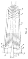
- Figure 15 shows diagrammatically part of a vessel similar to that shown in the right-hand side of Figure I which shows inclination of the transverse elements only in respect of the elements which are in contact with the wall of the vessel.
- Figure 16 shows another embodiment where there is a single layer of inserts where alternate pairs of inter-engaged transverse elements are alternately inclined.
- a three-dimensional array of inserts may also have inclined transverse elements either arranged with interstitially disposed transverse elements being inclined in the same direction, particularly where the angle of inclination is relatively small; or in the opposite direction.
- the internal passageway may be eccentrically disposed and/or a plurality of internal passageways may be provided within the assembly, depending upon the configuration of the vessel with which the assembly is to be used. The interstitial disposition of the transverse elements ensures that there are provided within the vessel well distributed, similarly sized voids between the transverse elements so that good distribution of fluid flowing through the packing is achieved so that maldistribution of fluid is minimized.
- junction points of contact are achieved where the individual insterstitially disposed transverse elements are in contact or cross each other. These junction points aid the wetting of the packing which again minimizes maldistribution, i.e. a minute film exists at the junction point so that it becomes a preferential point of wetting, thus aiding the even distribution of liquid.
- a rigid mechanically strong packing is achieved such that the weight of packing in the vessel does not compress the packing further. Furthermore, in the operation of processing there can be fluctuations or vibrations in the flow of fluids through the packing, and since a packing embodying the invention is a rigid strong structure, there will be no compression of the packing as can occur with less rigid packing elements.
- the invention may be applied to a wide range of apparatus and processes, for example, as described hereinbefore, or drying, such as removable water and solvents from solids; recovery of solvents from adsorption columns; biological processes such as growing of bio-masses on solid surfaces; dissolving or stripping of gases; condensation in condensers or coils reverse osmosis, ultra-filtration, chromatography, fixed bed separation processes (gas or vapour - solid with inserts aiding vapour distribution).
- the inserts may themselves provide a catalyst or may support a catalyst which can be coated onto the inserts when a single phase or a plurality of phases are passed over the inserts. Alternatively, the inserts may be provided to act as a flame retardant.
- An assembly embodying the invention provides a higher unit surface area/unit volume of packing than that available hitherto and the packing can be used horizontally or vertically.
- the inserts may be acted upon by being deformed or displaced the method may be as described in connection with our previous specification No. GB-B-2097910 prior to assembly into an array.
Landscapes
- Chemical & Material Sciences (AREA)
- Physics & Mathematics (AREA)
- Thermal Sciences (AREA)
- Engineering & Computer Science (AREA)
- Organic Chemistry (AREA)
- Chemical Kinetics & Catalysis (AREA)
- Mechanical Engineering (AREA)
- General Engineering & Computer Science (AREA)
- Physical Or Chemical Processes And Apparatus (AREA)
- Closures For Containers (AREA)
- Containers Having Bodies Formed In One Piece (AREA)
- Devices For Use In Laboratory Experiments (AREA)
- Vaporization, Distillation, Condensation, Sublimation, And Cold Traps (AREA)
- Medicines That Contain Protein Lipid Enzymes And Other Medicines (AREA)
- Infusion, Injection, And Reservoir Apparatuses (AREA)
Claims (16)
- Füllkörper für einen Behälter, wobei der Füllkörper (1) eine Mehrzahl von Einsetzeinheiten (12) aufweist, die jeweils einen länglichen Kern (13) mit einer Mehrzahl von sich längs erstreckenden, an unterschiedlichen Positionen entlang des Kerns und mit unterschiedlichen Winkelausrichtungen um den Kern angeordneten Elementen (16), dadurch gekennzeichnet, daß die Einsetzeinheiten (12) regelmäßig und Seite an Seite angeordnet sind, wobei der Kern jeder Einheit außerhalb jeder der benachbarten Einheiten angeordnet ist und wenigstens ein sich quer erstreckendes Element (16) jeder Einheit relativ zu den sich quer erstreckenden Elementen (16) einer benachbarten Einheit (12) versetzt angeordnet ist.
- Füllkörper für einen Behälter nach Anspruch 1, wobei ein radial am weitesten außen liegender Abschnitt jedes Querelements in großer Nähe zu einer ersten einzelnen gedachten Umhüllungsfläche (S₁) liegt und die Querschnittsfläche zwischen benachbarten sich überlappenden einzelnen gedachten Flächen (S₁) benachbarter Einsetzeinheiten (12) wenigstens an einem Ort längs der Mehrzahl von Einsetzeinheiten (12) nicht größer ist als die maximale Querschnittsfläche innerhalb einer einzelnen gedachten Fläche (S₁) einer Einsetzeinheit (12) zwischen zwei benachbarten sich quer erstreckenden Elementen (16) bei jedem Querschnitt längs der Mehrzahl von Einheiten.
- Füllkörper nach Anspruch 1 Anspruch 2, wobei wenigstens ein sich quer erstreckendes Element (16) auf Lücke zwischen radial benachbarten oder longitudinal benachbarten oder radial und longitudinal benachbarten Querelementen (16) einer benachbarten Einheit angeordnet ist.
- Füllkörper nach einem der vorangehenden Ansprüche, wobei der Kern (13) zwei miteinander verdrehte gestreckte Elemente (13a, 13b) aufweist, die jeweils eine Schlaufe (16) mit wenigstens einer Drehung einer schraubenförmigen Windung (14) bilden, und ein Teil jeder der Schlaufen (16) zwischen den miteinander verdrehten Elementen (13a, 13b) gehalten wird.
- Füllkörper nach einem der vorangehenden Ansprüche, wobei die Elemente (16) derart angeordnet sind, daß über die Länge des Füllkörpers kein oder kein wesentlicher geradliniger Flußweg für ein Fluid gegeben ist.
- Füllkörper nach Anspruch 2 oder einem der Ansprüche 3 bis 6 in Abhängigkeit von Anspruch 2, dadurch gekennzeichnet, daß die Einsetzeinheiten (12) derart angeordnet sind, daß die gedachten Flächen (S₁) einander ohne Spalt zwischen den gedachten Flächen (S₁) überlappen.
- Füllkörper nach einem der vorangehenden Ansprüche, wobei jedes Querelement (16) eine Schlaufe aus einem faserigen Material aufweist und wobei Linien, die lateral geradlinige Linien (15a, 15b) jeder Schlaufe rechtwinklig schneiden und durch die Seiten der Schlaufen (16) verlaufen, geradlinig und und im wesentlichen parallel zu einer diametralen Ebene des Kerns (13) verlaufen.
- Füllkörper nach einem der vorangehenden Ansprüche, wobei jede Einsetzeinheit (12) einen gesonderten Einsatz aufweist.
- Füllkörper nach einem der Anspruch 1 bis 7, wobei jede Einsetzeinheit einen Teil eines einzelnen Einsatzes (12a, 12b, 12c) aufweist, der derart geformt ist, daß die Teile Seite an Seite angeordnet sind.
- Füllkörper nach einem der vorangehenden Ansprüche, wobei die Querelemente (16) an einer Umfangsfläche (E₁, E₂) des Füllkörpers in Bezug auf die Form der Querelemente an Orten mit Abstand von der Umfangsfläche deformiert sind.
- Füllkörper nach einem der vorangehenden Ansprüche, wobei die Querelemente (16) an einer Umfangsfläche (E₁, E₂) des Füllkörpers in Bezug auf die Form der Querelemente an Orten mit Abstand von der Umfangsfläche verlagert sind.
- Füllkörper nach einem der vorangehenden Ansprüche in einem Behälter (10) zum Kontaktieren bei Verwendung eines sich in diesem befindlichen Fluids und wobei die einer Wandung des Behälters benachbarten Querelemente der Form der Wandung des Kessels entsprechen.
- Füllkörper nach Anspruch 12, wobei radial am weitesten außen liegende Teile jedes Querelements (16) einer Einsetzeinheit (12) auf einer gedachten Umhüllungsfläche (E¹) liegen und die einer Wandung des Behälters benachbarten Querelemente (16) der Form der Wandung des Behälters ohne Spalt zwischen der gedachten Umhüllungsflächen entsprechend und ohne Bildung eines gestreckten Flußweges benachbart der Wandung angeordnet sind.
- Verfahren zum Herstellen eines Füllkörpers (11) zur Einbringung in einen Behälter (10) zum Kontaktieren eines Fluids in diesem, unter Nehmen einer aus einer Mehrzahl von Einsetzeinheiten (12) bestehenden Menge, die jeweils einen länglichen Kern (13) mit einer Mehrzahl von sich längs erstreckenden, an unterschiedlichen Positionen entlang des Kerns und mit unterscheidlichen Winkelausrichtungen um den Kern angeordneten Elementen (16) haben, dadurch gekennzeichnet, daß die Einsetzeinheiten (12) regelmäßig und Seite an Seite angeordnet sind, wobei der Kern jeder Einheit außerhalb jeder der benachbarten Einheiten angeordnet ist und wobei ein Abschnitt jedes sich quer erstreckenden Elements (16) benachbart einer Umfangsfläche (E₁, E₂) der Menge in großer Nähe zu einer ersten gedachten Gesamtumhüllungsfläche (E¹) liegt und wobei das Verfahren weiter den Schritt des Einwirkens auf die sich quer erstreckenden Elemente (16) benachbart der Umfangsfläche (E₁, E₂) unter Verursachung eines Liegens eines Abschnitts von diesem in großer Nähe zu einer zweiten gedachten Gesamtumhüllungsfläche mit kleinerer Querschnittsfläche als derjenigen der ersten gedachten Gesamtumhüllungsfläche (E¹) und unter Verursachung einer versetzten Anordnung wenigstens eines sich quer erstreckenden Elements (16) einer Einheit (12) in Bezug auf die sich quer erstreckenden Elemente (16) einer benachbarten Einheit (16) aufweist.
- Verfahren nach Anspruch 14, wobei das Verfahren den Schritt des Einwirkens auf eine Mehrzahl von Einsetzeinheiten (12) durch deren Führen durch konische Führungsteile (33) eines Zugangsabschnitts (32) eines Werkzeugs (30) und Herausziehen des Füllkörpers aus einem Rohr (31) des Werkzeugs (30) aufweist.
- Verfahren zum Herstellen eines Behälters (10), der einen länglichen rohrförmigen Abschnitt (10b) mit einem in diesem angeordneten Füllmaterial (11) zum Kontaktieren von Fluid aufweist, dadurch gekennzeichnet, daß das Füllmaterial nach einem der Ansprüche 14 oder 15 gefertigt ist, und die zweite gedachte Gesamtumhüllungsfläche eine Querschnittsausbildung hat, die derjenigen des rohrförmigen Abschnitts (10b) gleich oder im wesentlichen gleich ist, so daß der Abschnitt jedes sich quer erstreckenden Elements (16) in großer Nähe zu dem rohrförmigen Abschnitt (10b) eine größere Ausdehnung hat als diese in großer Nähe zu der ersten gedachten Fläche (E₁) war.
Applications Claiming Priority (2)
| Application Number | Priority Date | Filing Date | Title |
|---|---|---|---|
| GB888827731A GB8827731D0 (en) | 1988-11-28 | 1988-11-28 | Packed vessel |
| GB8827731 | 1988-11-28 |
Publications (2)
| Publication Number | Publication Date |
|---|---|
| EP0445203A1 EP0445203A1 (de) | 1991-09-11 |
| EP0445203B1 true EP0445203B1 (de) | 1993-10-20 |
Family
ID=10647578
Family Applications (1)
| Application Number | Title | Priority Date | Filing Date |
|---|---|---|---|
| EP19900900235 Expired - Lifetime EP0445203B1 (de) | 1988-11-28 | 1989-11-28 | Füllkörper in einem oder für einen behälter |
Country Status (10)
| Country | Link |
|---|---|
| US (1) | US5194231A (de) |
| EP (1) | EP0445203B1 (de) |
| JP (1) | JPH04503919A (de) |
| KR (1) | KR900701390A (de) |
| AT (1) | ATE96052T1 (de) |
| AU (1) | AU4750190A (de) |
| CA (1) | CA2004008A1 (de) |
| DE (1) | DE68910133T2 (de) |
| GB (2) | GB8827731D0 (de) |
| WO (1) | WO1990006175A1 (de) |
Cited By (1)
| Publication number | Priority date | Publication date | Assignee | Title |
|---|---|---|---|---|
| US12303859B2 (en) | 2019-08-27 | 2025-05-20 | Sabic Global Technologies B.V. | Mass transfer swirler including distribution member |
Families Citing this family (28)
| Publication number | Priority date | Publication date | Assignee | Title |
|---|---|---|---|---|
| BE1003962A3 (fr) * | 1989-07-20 | 1992-07-28 | Gilson Robert | Filtre biologique immergeable pour l'epuration des eaux usees. |
| US5195139A (en) * | 1991-05-15 | 1993-03-16 | Ensoniq Corporation | Hearing aid |
| PL308989A1 (en) * | 1995-06-08 | 1996-12-09 | B Donald E Prazmowski | Biological bed |
| US5776380A (en) * | 1996-11-15 | 1998-07-07 | Kem-Wove Incorporated | Chemical and microbiological resistant evaporative cooler media and processes for making the same |
| US5985148A (en) * | 1997-12-12 | 1999-11-16 | Liu; Kai Yuan | Water treatment filter wool balls |
| US6371452B1 (en) * | 1998-09-06 | 2002-04-16 | Saeed M. Shojaie | Packing unit |
| US6190555B1 (en) * | 1999-02-18 | 2001-02-20 | Masao Kondo | Apparatus and method for biological treatment of wastewater |
| US20030111744A1 (en) * | 2000-05-18 | 2003-06-19 | Manteufel Rolf P.C. | Device for guiding the flow of a liquid used for material and/or energy exchange in a wash column |
| US20040091402A1 (en) * | 2000-10-27 | 2004-05-13 | Thomas Lewin | Insert for an exhaust gas channel |
| SE517458C2 (sv) * | 2000-10-27 | 2002-06-11 | Sandvik Ab | Insats i avgaskanal för skapande av turbulent flöde |
| JP2002130975A (ja) * | 2000-10-30 | 2002-05-09 | Japan Atom Energy Res Inst | 金属細線多孔体による伝熱促進法 |
| DE102004005863A1 (de) * | 2004-02-05 | 2005-09-08 | Stockhausen Gmbh | Reaktor mit einem einen Einsatz aufweisenden Wärmetauscherbereich |
| WO2006100072A1 (de) * | 2005-03-24 | 2006-09-28 | Behr Gmbh & Co. Kg | Abgaswärmeübertrager, insbesondere abgaskühler für eine abgasrückführung in kraftfahrzeugen |
| US20070181474A1 (en) * | 2006-02-03 | 2007-08-09 | Union Looper Co., Ltd. | Filter for a microbe reactor of sewage treatment |
| FR2898406A1 (fr) * | 2006-03-13 | 2007-09-14 | Peugeot Citroen Automobiles Sa | Element pour ameliorer les echanges thermiques entre un objet et un fluide en circulation et dispositif a echange thermique |
| US8656753B1 (en) * | 2008-06-06 | 2014-02-25 | Paul H. Silvis | Sleeve units, and inlet liner inserts therefor, used for preparing a sample for gas chromatographic analysis |
| JP2011125841A (ja) * | 2009-11-17 | 2011-06-30 | Kiriyama Seisakusho:Kk | 蒸留用充填物 |
| RU2440843C2 (ru) * | 2010-03-09 | 2012-01-27 | Государственное образовательное учреждение высшего профессионального образования "Московский государственный университет инженерной экологии" | Способ регулярной укладки кольцевой насадки |
| US9295960B2 (en) | 2012-03-23 | 2016-03-29 | United Technologies Corporation | Catalytic reaction in confined flow channel |
| EP3357871A4 (de) * | 2015-09-30 | 2019-05-22 | Bitech Co., Ltd. | Abwasserbehandlungsträger, abwasserbehandlungsträgermodul, abwasserbehandlungsträgereinheit und abwasserbehandlungsvorrichtung |
| US10913667B2 (en) * | 2017-12-08 | 2021-02-09 | Westech Engineering, Inc. | Multi-media clarification systems and methods |
| RU2746140C2 (ru) * | 2018-06-28 | 2021-04-07 | Общество с ограниченной ответственностью "Стандартиммаш" | Способ загрузки кольцевых насадок в колонные аппараты |
| WO2020174169A1 (fr) * | 2019-02-25 | 2020-09-03 | L'air Liquide, Societe Anonyme Pour L'etude Et L'exploitation Des Procedes Georges Claude | Appareil d'échange de chaleur et de matière |
| RU191966U1 (ru) * | 2019-02-27 | 2019-08-28 | Федеральное государственное бюджетное образовательное учреждение высшего образования "Волгоградский государственный технический университет" (ВолгГТУ) | Насадка тепломассообменного аппарата |
| EP4093529B1 (de) * | 2020-03-17 | 2025-06-25 | Fluid Handling LLC | Koaleszenzmittel für hydronische luft- und sedimenttrennvorrichtung |
| US11583788B1 (en) * | 2022-01-18 | 2023-02-21 | Theodore A. Kuepper | Lightweight fibrous media (LFM) filter |
| CN117365747A (zh) | 2022-07-01 | 2024-01-09 | 通用电气公司 | 用于碳氢流体的自清洁导管 |
| CN117365748A (zh) * | 2022-07-01 | 2024-01-09 | 通用电气公司 | 用于碳氢流体的自清洁导管 |
Family Cites Families (17)
| Publication number | Priority date | Publication date | Assignee | Title |
|---|---|---|---|---|
| FR540647A (fr) * | 1921-09-05 | 1922-07-13 | Perfectionnements aux appareils de condensation, d'absorption, de lavage ou de dissolution des gaz et des vapeurs | |
| DE532764C (de) * | 1927-08-12 | 1932-04-07 | Hugo Kosmack | Fuellkoerper |
| GB607288A (en) * | 1944-04-03 | 1948-08-27 | Francis Leopold Melville | Improvements in gas or vapour and liquid contacting methods and apparatus |
| US2867425A (en) * | 1956-10-05 | 1959-01-06 | Harshaw Chem Corp | Mass transfer process and packing units therefor |
| US3438614A (en) * | 1967-09-22 | 1969-04-15 | Frank Lipinski | Tower packing |
| US3799854A (en) * | 1970-06-19 | 1974-03-26 | Ppg Industries Inc | Method of electrodepositing cationic compositions |
| US3752453A (en) * | 1971-02-19 | 1973-08-14 | Ceilcote Co Inc | Packing material unit |
| US3949970A (en) * | 1974-01-02 | 1976-04-13 | Gebrs. ter Braak B.V. | Mixer |
| US4201736A (en) * | 1977-07-26 | 1980-05-06 | Bott Theodore R | Fluid distribution and contacting elements |
| HU179455B (en) * | 1979-07-16 | 1982-10-28 | Energiagazdalkodasi Intezet | Ribbed device improving the heat transfer composed from sheet strips |
| AT380335B (de) * | 1980-03-25 | 1986-05-12 | Faigle Kunststoff Gmbh | Fuellkoerper fuer anlagen zum energie- und/oder stoffaustausch oder tropfenabscheider und dgl. |
| US4411942A (en) * | 1980-11-18 | 1983-10-25 | Bayer Aktiengesellschaft | Packing for technical processes |
| US4481154A (en) * | 1981-03-20 | 1984-11-06 | Cal Gavin Limited | Insert for placement in a vessel and method of forming the insert |
| GB2097910B (en) * | 1981-03-20 | 1984-10-31 | Gavin Cal Ltd | Insert for placement in a vessel |
| US4419467A (en) * | 1981-09-14 | 1983-12-06 | Ppg Industries, Inc. | Process for the preparation of cationic resins, aqueous, dispersions, thereof, and electrodeposition using the aqueous dispersions |
| DE3311516A1 (de) * | 1983-03-30 | 1984-10-04 | Basf Farben + Fasern Ag, 2000 Hamburg | Hitzehaertbare ueberzugsmittel und deren verwendung |
| AT396178B (de) * | 1985-08-02 | 1993-06-25 | Faigle Kunststoff Gmbh | Fuellkoerper fuer anlagen zum energie- und/oder stoffaustausch zwischen gas- und/oder fluessigen medien oder tropfenabscheider |
-
1988
- 1988-11-28 GB GB888827731A patent/GB8827731D0/en active Pending
-
1989
- 1989-11-28 US US07/689,853 patent/US5194231A/en not_active Expired - Fee Related
- 1989-11-28 KR KR1019900701653A patent/KR900701390A/ko not_active Withdrawn
- 1989-11-28 EP EP19900900235 patent/EP0445203B1/de not_active Expired - Lifetime
- 1989-11-28 AU AU47501/90A patent/AU4750190A/en not_active Abandoned
- 1989-11-28 CA CA002004008A patent/CA2004008A1/en not_active Abandoned
- 1989-11-28 JP JP2500715A patent/JPH04503919A/ja active Pending
- 1989-11-28 AT AT90900235T patent/ATE96052T1/de not_active IP Right Cessation
- 1989-11-28 DE DE90900235T patent/DE68910133T2/de not_active Expired - Fee Related
- 1989-11-28 WO PCT/GB1989/001419 patent/WO1990006175A1/en not_active Ceased
-
1991
- 1991-05-23 GB GB9111141A patent/GB2243795B/en not_active Expired - Lifetime
Cited By (1)
| Publication number | Priority date | Publication date | Assignee | Title |
|---|---|---|---|---|
| US12303859B2 (en) | 2019-08-27 | 2025-05-20 | Sabic Global Technologies B.V. | Mass transfer swirler including distribution member |
Also Published As
| Publication number | Publication date |
|---|---|
| JPH04503919A (ja) | 1992-07-16 |
| GB8827731D0 (en) | 1988-12-29 |
| DE68910133D1 (de) | 1993-11-25 |
| GB2243795B (en) | 1992-10-28 |
| KR900701390A (ko) | 1990-12-01 |
| EP0445203A1 (de) | 1991-09-11 |
| DE68910133T2 (de) | 1994-05-05 |
| GB9111141D0 (en) | 1991-07-17 |
| AU4750190A (en) | 1990-06-26 |
| US5194231A (en) | 1993-03-16 |
| ATE96052T1 (de) | 1993-11-15 |
| CA2004008A1 (en) | 1990-05-28 |
| GB2243795A (en) | 1991-11-13 |
| WO1990006175A1 (en) | 1990-06-14 |
Similar Documents
| Publication | Publication Date | Title |
|---|---|---|
| EP0445203B1 (de) | Füllkörper in einem oder für einen behälter | |
| EP0554567B1 (de) | Gewebekartuschen mit spiralförmig gewickelten Hohlfasermembranen und Module mit strömungsableitenden Einbauten | |
| EP1857174B1 (de) | Reaktor mit expandierbarer Struktur und verbesserter Wärmeübertragung | |
| JP4787856B2 (ja) | 積層物に基づく管型反応器 | |
| KR100447518B1 (ko) | 촉매증류구조물 | |
| US7111673B2 (en) | System for stripping and rectifying a fluid mixture | |
| EP0807462A1 (de) | Strukturierte Packungselement mit texturierter Oberfläche in zwei Richtungen sowie Masse- und Wärmeaustauschverfahren unter Verwendung desselben | |
| US5092038A (en) | Method of manufacturing spiral heat exchanger tubes with an external fin | |
| JPH0417350B2 (de) | ||
| US4002705A (en) | Fluid-fluid contact apparatus | |
| RU2454275C2 (ru) | Насадочная структура для колонны для обеспечения контакта текучих сред и способ ее изготовления | |
| JP2004534636A (ja) | 1種以上の毒性成分を含む混合物の蒸留又は反応蒸留 | |
| EP0061154B1 (de) | Einlage für ein Rohr und Verfahren zu dessen Herstellung | |
| US4366608A (en) | Method for manufacturing fluid contacting device | |
| US2591878A (en) | Oxygen regenerator | |
| US20040140577A1 (en) | Structured packing | |
| EP0916400A1 (de) | Rektifikationskolonne unter Anwendung von strukturierte Packung zur Reduktion von Wandströmung | |
| US5688444A (en) | Tower packing element | |
| US5730000A (en) | Structured packing element and a mass and heat transfer process using such packing element | |
| JPH0783822B2 (ja) | 最小有効膜厚を有する液体膜モジュールと、その製造方法 | |
| US4581800A (en) | Method of making a segmented externally finned heat exchanger tube | |
| GB2097910A (en) | Insert for placement in vessel | |
| DE3878970T2 (de) | Praeparative chromatographiesaeule. | |
| EP1752214A1 (de) | Packung fuer eine Austauschkolonn | |
| CA2084380A1 (en) | Counter-current flow hollow fiber permeator |
Legal Events
| Date | Code | Title | Description |
|---|---|---|---|
| PUAI | Public reference made under article 153(3) epc to a published international application that has entered the european phase |
Free format text: ORIGINAL CODE: 0009012 |
|
| 17P | Request for examination filed |
Effective date: 19910527 |
|
| AK | Designated contracting states |
Kind code of ref document: A1 Designated state(s): AT BE CH DE ES FR GB IT LI LU NL SE |
|
| 17Q | First examination report despatched |
Effective date: 19911213 |
|
| GRAA | (expected) grant |
Free format text: ORIGINAL CODE: 0009210 |
|
| AK | Designated contracting states |
Kind code of ref document: B1 Designated state(s): AT BE CH DE ES FR GB IT LI LU NL SE |
|
| PG25 | Lapsed in a contracting state [announced via postgrant information from national office to epo] |
Ref country code: SE Effective date: 19931020 Ref country code: ES Free format text: THE PATENT HAS BEEN ANNULLED BY A DECISION OF A NATIONAL AUTHORITY Effective date: 19931020 Ref country code: AT Effective date: 19931020 |
|
| REF | Corresponds to: |
Ref document number: 96052 Country of ref document: AT Date of ref document: 19931115 Kind code of ref document: T |
|
| REF | Corresponds to: |
Ref document number: 68910133 Country of ref document: DE Date of ref document: 19931125 |
|
| PG25 | Lapsed in a contracting state [announced via postgrant information from national office to epo] |
Ref country code: LU Free format text: LAPSE BECAUSE OF NON-PAYMENT OF DUE FEES Effective date: 19931130 |
|
| ITF | It: translation for a ep patent filed | ||
| ET | Fr: translation filed | ||
| RAP4 | Party data changed (patent owner data changed or rights of a patent transferred) |
Owner name: HITRAN (ISLE OF MAN) LIMITED |
|
| REG | Reference to a national code |
Ref country code: CH Ref legal event code: PFA Free format text: HITRAN (ISLE OF MAN) LIMITED |
|
| NLT1 | Nl: modifications of names registered in virtue of documents presented to the patent office pursuant to art. 16 a, paragraph 1 |
Owner name: HITRAN (ISLE OF MAN) LIMITED TE DOUGLAS, GROOT-BRI |
|
| PLBE | No opposition filed within time limit |
Free format text: ORIGINAL CODE: 0009261 |
|
| STAA | Information on the status of an ep patent application or granted ep patent |
Free format text: STATUS: NO OPPOSITION FILED WITHIN TIME LIMIT |
|
| 26N | No opposition filed | ||
| PGFP | Annual fee paid to national office [announced via postgrant information from national office to epo] |
Ref country code: FR Payment date: 19981110 Year of fee payment: 10 |
|
| PGFP | Annual fee paid to national office [announced via postgrant information from national office to epo] |
Ref country code: NL Payment date: 19981126 Year of fee payment: 10 |
|
| PGFP | Annual fee paid to national office [announced via postgrant information from national office to epo] |
Ref country code: GB Payment date: 19981204 Year of fee payment: 10 |
|
| PGFP | Annual fee paid to national office [announced via postgrant information from national office to epo] |
Ref country code: DE Payment date: 19981207 Year of fee payment: 10 |
|
| PGFP | Annual fee paid to national office [announced via postgrant information from national office to epo] |
Ref country code: CH Payment date: 19981210 Year of fee payment: 10 |
|
| PGFP | Annual fee paid to national office [announced via postgrant information from national office to epo] |
Ref country code: BE Payment date: 19990119 Year of fee payment: 10 |
|
| PG25 | Lapsed in a contracting state [announced via postgrant information from national office to epo] |
Ref country code: GB Free format text: LAPSE BECAUSE OF NON-PAYMENT OF DUE FEES Effective date: 19991128 |
|
| PG25 | Lapsed in a contracting state [announced via postgrant information from national office to epo] |
Ref country code: LI Free format text: LAPSE BECAUSE OF NON-PAYMENT OF DUE FEES Effective date: 19991130 Ref country code: CH Free format text: LAPSE BECAUSE OF NON-PAYMENT OF DUE FEES Effective date: 19991130 Ref country code: BE Free format text: LAPSE BECAUSE OF NON-PAYMENT OF DUE FEES Effective date: 19991130 |
|
| BERE | Be: lapsed |
Owner name: HITRAN (ISLE OF MAN) LTD Effective date: 19991130 |
|
| PG25 | Lapsed in a contracting state [announced via postgrant information from national office to epo] |
Ref country code: NL Free format text: LAPSE BECAUSE OF NON-PAYMENT OF DUE FEES Effective date: 20000601 |
|
| REG | Reference to a national code |
Ref country code: CH Ref legal event code: PL |
|
| GBPC | Gb: european patent ceased through non-payment of renewal fee |
Effective date: 19991128 |
|
| PG25 | Lapsed in a contracting state [announced via postgrant information from national office to epo] |
Ref country code: FR Free format text: LAPSE BECAUSE OF NON-PAYMENT OF DUE FEES Effective date: 20000731 |
|
| NLV4 | Nl: lapsed or anulled due to non-payment of the annual fee |
Effective date: 20000601 |
|
| PG25 | Lapsed in a contracting state [announced via postgrant information from national office to epo] |
Ref country code: DE Free format text: LAPSE BECAUSE OF NON-PAYMENT OF DUE FEES Effective date: 20000901 |
|
| REG | Reference to a national code |
Ref country code: FR Ref legal event code: ST |
|
| PG25 | Lapsed in a contracting state [announced via postgrant information from national office to epo] |
Ref country code: IT Free format text: LAPSE BECAUSE OF NON-PAYMENT OF DUE FEES Effective date: 20051128 |