EP0445046A1 - Schraubenpumpe, Motorpumpe, Behälter und mit derartiger Pumpe ausgerüstetes Gerät - Google Patents
Schraubenpumpe, Motorpumpe, Behälter und mit derartiger Pumpe ausgerüstetes Gerät Download PDFInfo
- Publication number
- EP0445046A1 EP0445046A1 EP91420049A EP91420049A EP0445046A1 EP 0445046 A1 EP0445046 A1 EP 0445046A1 EP 91420049 A EP91420049 A EP 91420049A EP 91420049 A EP91420049 A EP 91420049A EP 0445046 A1 EP0445046 A1 EP 0445046A1
- Authority
- EP
- European Patent Office
- Prior art keywords
- opening
- screw
- pump
- pump according
- liquid
- Prior art date
- Legal status (The legal status is an assumption and is not a legal conclusion. Google has not performed a legal analysis and makes no representation as to the accuracy of the status listed.)
- Withdrawn
Links
Images

Classifications
-
- A—HUMAN NECESSITIES
- A47—FURNITURE; DOMESTIC ARTICLES OR APPLIANCES; COFFEE MILLS; SPICE MILLS; SUCTION CLEANERS IN GENERAL
- A47L—DOMESTIC WASHING OR CLEANING; SUCTION CLEANERS IN GENERAL
- A47L15/00—Washing or rinsing machines for crockery or tableware
- A47L15/42—Details
- A47L15/44—Devices for adding cleaning agents; Devices for dispensing cleaning agents, rinsing aids or deodorants
- A47L15/4418—Devices for adding cleaning agents; Devices for dispensing cleaning agents, rinsing aids or deodorants in the form of liquids
-
- D—TEXTILES; PAPER
- D06—TREATMENT OF TEXTILES OR THE LIKE; LAUNDERING; FLEXIBLE MATERIALS NOT OTHERWISE PROVIDED FOR
- D06F—LAUNDERING, DRYING, IRONING, PRESSING OR FOLDING TEXTILE ARTICLES
- D06F39/00—Details of washing machines not specific to a single type of machines covered by groups D06F9/00 - D06F27/00
- D06F39/02—Devices for adding soap or other washing agents
- D06F39/022—Devices for adding soap or other washing agents in a liquid state
-
- F—MECHANICAL ENGINEERING; LIGHTING; HEATING; WEAPONS; BLASTING
- F04—POSITIVE - DISPLACEMENT MACHINES FOR LIQUIDS; PUMPS FOR LIQUIDS OR ELASTIC FLUIDS
- F04D—NON-POSITIVE-DISPLACEMENT PUMPS
- F04D1/00—Radial-flow pumps, e.g. centrifugal pumps; Helico-centrifugal pumps
- F04D1/02—Radial-flow pumps, e.g. centrifugal pumps; Helico-centrifugal pumps having non-centrifugal stages, e.g. centripetal
- F04D1/025—Comprising axial and radial stages
-
- F—MECHANICAL ENGINEERING; LIGHTING; HEATING; WEAPONS; BLASTING
- F04—POSITIVE - DISPLACEMENT MACHINES FOR LIQUIDS; PUMPS FOR LIQUIDS OR ELASTIC FLUIDS
- F04D—NON-POSITIVE-DISPLACEMENT PUMPS
- F04D29/00—Details, component parts, or accessories
- F04D29/08—Sealings
- F04D29/086—Sealings especially adapted for liquid pumps
-
- F—MECHANICAL ENGINEERING; LIGHTING; HEATING; WEAPONS; BLASTING
- F04—POSITIVE - DISPLACEMENT MACHINES FOR LIQUIDS; PUMPS FOR LIQUIDS OR ELASTIC FLUIDS
- F04D—NON-POSITIVE-DISPLACEMENT PUMPS
- F04D29/00—Details, component parts, or accessories
- F04D29/18—Rotors
- F04D29/185—Rotors consisting of a plurality of wheels
-
- F—MECHANICAL ENGINEERING; LIGHTING; HEATING; WEAPONS; BLASTING
- F04—POSITIVE - DISPLACEMENT MACHINES FOR LIQUIDS; PUMPS FOR LIQUIDS OR ELASTIC FLUIDS
- F04D—NON-POSITIVE-DISPLACEMENT PUMPS
- F04D29/00—Details, component parts, or accessories
- F04D29/40—Casings; Connections of working fluid
- F04D29/52—Casings; Connections of working fluid for axial pumps
- F04D29/54—Fluid-guiding means, e.g. diffusers
- F04D29/548—Specially adapted for liquid pumps
-
- F—MECHANICAL ENGINEERING; LIGHTING; HEATING; WEAPONS; BLASTING
- F04—POSITIVE - DISPLACEMENT MACHINES FOR LIQUIDS; PUMPS FOR LIQUIDS OR ELASTIC FLUIDS
- F04D—NON-POSITIVE-DISPLACEMENT PUMPS
- F04D3/00—Axial-flow pumps
- F04D3/02—Axial-flow pumps of screw type
Definitions
- the present invention relates to rotary screw pumps.
- Screw pumps are widely known and used, in particular for pumping hydraulic fluid.
- document GB-C-1 494 091 describes a rotary screw pump, comprising a tubular body, an endless screw (2) rotatably mounted in said body, around the axis of the tubular part, said communicating body. on the upstream side with a liquid suction opening, and on the downstream side with a discharge opening for the liquid pumped into a chamber.
- This opening for the expulsion of a liquid stream has an internal cross section adapted to the external cross section of the downstream end of the screw, with the functional clearance necessary for the rotation of the latter in the delivery opening.
- the invention is concerned with the use of such pumps in the field of washing, in particular the industrial washing of linen or dishes, it being understood that the same invention cannot be limited to such a field, as regards its application, its scope, and its interpretation.
- the object of the present invention is therefore to adapt screw pumps to the constraints described above, in particular in the context of industrial washing equipment or machines.
- this adaptation can be obtained by arranging a swirl means around the axis of the tubular part of the pump body, outside of said part, said means being intended to be immersed in a bath, for example a wash water bath. And this swirling means is further arranged or arranged, to take up and suck up, under the effect of the swirl generated in the bath, the liquid vein expelled by the screw in the delivery opening, with or without the addition complementary guiding means of the liquid stream of the screw towards said swirling means.
- the present invention unexpectedly provides a decisive advantage relating to priming the pump. It follows from the preceding observations that the pumping of the detergent liquid is correct, in terms of flow rate, only thanks to the low pressure effect achieved within the bath, by the swirling means at the outlet of the delivery opening.
- the flow rate of the detergent liquid is dependent on the presence or absence of liquid in the bath, and the invention provides an automatic means of priming the pump, if liquid is present in the delivery opening, and disarming, if no liquid is present in this opening.
- the invention provides an automatic means of priming the pump, if liquid is present in the delivery opening, and disarming, if no liquid is present in this opening.
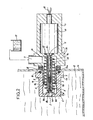
- the latter comprises a body 1 made of a plastic material resistant to corrosion, in particular that provided by detergents, while having good mechanical properties, in particular with respect to thermal shocks encountered during operation.
- this body comprises, from left to right of FIG. 1, a tubular part 1a, externally threaded, determining at its open end a delivery opening 5, a flange 1b of larger outside diameter, determining a suction chamber 36 of relatively large volume, and into which opens a radial tube forming suction opening 4 detergent liquid to be pumped, and finally a cylindrical part 1c incorporating the electric motor 10 for driving the pump.
- the parts 1a, 1b and 1c previously described are aligned coaxially.
- a worm 2 comprising a single helical thread 2b, is rotatably mounted in the body 1 , and more precisely in the tubular part 1a, around the axis 3 of the latter.
- This screw extends along the axis 3, from an upstream end 2c, located inside the body 2, downstream of the suction chamber 16, to a downstream end 2d, located in the opening 5 of repression.
- the thread 2b of the screw 2 at constant pitch, develops continuously from the upstream end 2c to the downstream end 2d of said screw.
- the discharge opening 5 has an internal cross section adapted to the external cross section, overall, of the downstream end 2d of the screw, apart from the functional clearance.
- a ferrule flared upstream of the screw 2, of conical shape is disposed substantially in a plane perpendicular to the axis 3 of the tubular part 1a, in the discharge opening 5, at the downstream end 2d of the screw 2, and this in continuity with the thread of the latter, as shown in FIG. 1.
- a paddle wheel 51 is mounted or integral, coaxially in the circular downstream opening 50a of the flared ferrule 50.
- This wheel 51, having vanes or fins 52 is disposed around the axis 3 of the tubular part 1a, outside of the latter, and at the outlet of the discharge opening 5.
- the screw 2, the ferrule 50 and the wheel 51 with blades are thus integral coxially in rotation, and form a single and same coaxial assembly.
- the peripheral liquid vein expelled by the delivery opening 5 has a cylindrical or tubular shape, at the outlet of the downstream opening 50a of the ferrule 50. Then this cylindrical vein is taken up by the impeller 51 with blades 52.
- the impeller 51 or blade wheel 51 has an axial passage 51a, in the extension of the downstream opening 50a of the flared ferrule 50, allowing the introduction of the cylindrical liquid vein expelled by said ferrule.
- Each blade 52 of the wheel 51 extends radially, from an internal end 52a, situated in the axial extension of the downstream circular opening 50a of the ferrule 50, to an external end 52b situated in the axial extension of the tubular wall 1a.
- An external sleeve 6 is mounted on the body 2, and more precisely comprises an internal thread cooperating with the external thread of the tubular part 1a. Any other method of mounting, for example by hard fitting, of the sleeve 6 on the body 2 can be envisaged.
- This socket comprises a base 6b, a sleeve 6c of smaller diameter, of shape covering the impeller 51, having two opposite passages 6d right through to ensure the passage of the washing bath, and a transverse flange 6a, arranged perpendicularly to axis 3 and connecting two opposite edges of the sleeve 6c.
- the coaxial assembly comprising the screw 2, the ferrule 50 and the wheel 51 is locked in rotation on a metal drive shaft, consisting of a rod 7, the outer end 7b of which is journalled on the flange 6a.
- the motor shaft 7 thus obtained is arranged coaxially with the screw 2, the ferrule 50 and the wheel 51, and extends from an inner end 7a situated on the side of the suction opening 4, at one end outer 7b, located outside the delivery opening 5, that is to say outside the tubular part 1a.
- the outer end 7b of the drive shaft is journalled on the outer sleeve 6, in a bearing 6d formed coaxially in the flange 6a.
- the motor shaft constituted by the metal rod 7 forms an electrode, thanks to the outer end 7b immersed in the washing bath, the other electrode being constituted by the mass 14 of the washing tank 13.
- the electric motor 10 for driving the screw 2 in rotation, by the motor shaft 7, is disposed completely in the cylindrical part 1c of the body 1. Its output shaft is coupled in rotation, by means not shown, to the 'motor shaft 7, and therefore to the coaxial assembly comprising the worm 2, the ferrule 50 and the wheel 51 with fins.
- An annular seal 12 forms a seal between the output shaft of the motor 10 and the body 1.
- a perforation 14a is provided in the wall 14 of the container in the washing tub 13. This perforation allows the sealed passage of the body 1, and more precisely of the tubular part 1a.
- Perforation 14a the wall 14 is clamped between the part 1b of the body 1 and the outer sleeve 6, thanks to the threads described between the sleeve 6 and the tubular part 1a. It is the same for the inner O-ring seal 16, clamped between the base 6b and the wall 14, and for the two flat outer seal 15 seals, clamped between the part 1b of the body 1 and the wall 14 .
- any other mode of fitting or leaktight passage of the body 1 in the wall 14 of the container 13 can be envisaged, for example with a seal with a conical bearing, which can only be extracted later by destroying said seal.
- the suction opening 4 communicates with a reserve 17 of the detergent product, and on the other hand the electric motor is supplied by wires 18 passing through sealingly the part 1c of the body 1.
- the worm 2 comprising a single helical thread 2b, is rotatably mounted in the body 1, and more precisely in the tubular part 1a, around the axis 3 of the latter.
- This screw extends along the axis 3, from an upstream end 2c, located inside the body 2, in the suction chamber 16, on the side of the suction opening 4, at a downstream end 2d located outside of the tubular part 1a of the body 1, within the washing bath, as described below.
- the thread 2b of the screw 2 at constant pitch, develops continuously from the upstream end 2c to the downstream end 2d of said screw.
- the discharge opening 5 has a circular cross section, adapted to the passage of the screw 2, with the functional clearance necessary for the rotation of the latter in the opening 5.
- the screw 2 is locked in rotation on a metallic motor shaft, consisting of a rod 7, partially hollow and internally threaded 7b, and of a screw 8 screwed into the thread 7b, the free head 8a of which forms a bearing shoulder against the downstream end 2d of the screw 2.
- the motor shaft 7, 8 thus obtained is arranged coaxially with the screw 2, and extends from an inner end 7a situated on the side of the suction opening 4, at an outer end 8a, located outside the discharge opening 5, that is to say outside the tubular part 1a.
- the outer end of the drive shaft, consisting of the screw head 8a is journalled on the flange 6a of the outer sleeve 6, in the bearing 6d formed coxially.
- the drive shaft constituted by the metal rod 7 and the metal screw 8 forms an electrode, thanks to the head 8a of the screw 8 immersed in the washing bath, the other electrode being constituted by the mass 14 of the washing tank 13.
- the pump described according to FIG. 2 by adding according to the invention a length of 10 mm to the screw 2, outside the tubular body. 1a, then it is possible to obtain a priming time of 9 seconds, with a nominal flow rate of the order of 24 liters per hour, and a suction height of one meter.
- the screw can have a diameter of 17 to 18 mm, with a pitch of 4.5 to 5.5 mm. According to this example, there is therefore also a substantial improvement in the priming time and the flow rate of the screw pumps envisaged according to the present invention.
Landscapes
- Engineering & Computer Science (AREA)
- Mechanical Engineering (AREA)
- General Engineering & Computer Science (AREA)
- Textile Engineering (AREA)
- Structures Of Non-Positive Displacement Pumps (AREA)
Applications Claiming Priority (4)
| Application Number | Priority Date | Filing Date | Title |
|---|---|---|---|
| FR9002756 | 1990-02-28 | ||
| FR9002756A FR2658871B1 (fr) | 1990-02-28 | 1990-02-28 | Pompe rotative a vis, moto-pompe, recipient et machine, equipes d'une telle pompe. |
| FR9012582 | 1990-10-08 | ||
| FR9012582A FR2667654A1 (fr) | 1990-10-08 | 1990-10-08 | Pompe rotative a vis, moto-pompe, recipient et machine, equipes d'une telle pompe. |
Publications (1)
| Publication Number | Publication Date |
|---|---|
| EP0445046A1 true EP0445046A1 (de) | 1991-09-04 |
Family
ID=26227906
Family Applications (1)
| Application Number | Title | Priority Date | Filing Date |
|---|---|---|---|
| EP91420049A Withdrawn EP0445046A1 (de) | 1990-02-28 | 1991-02-12 | Schraubenpumpe, Motorpumpe, Behälter und mit derartiger Pumpe ausgerüstetes Gerät |
Country Status (2)
| Country | Link |
|---|---|
| EP (1) | EP0445046A1 (de) |
| CA (1) | CA2036984A1 (de) |
Cited By (2)
| Publication number | Priority date | Publication date | Assignee | Title |
|---|---|---|---|---|
| WO1995029282A1 (de) * | 1994-04-27 | 1995-11-02 | Henkel-Ecolab Gmbh & Co. Ohg | Verfahren und vorrichtung zum entleeren eines mit einer thixotropen paste gefüllten behälters |
| EP0713978A1 (de) * | 1994-11-25 | 1996-05-29 | Fujikoki Mfg. Co., Ltd. | Abflusspumpe |
Families Citing this family (1)
| Publication number | Priority date | Publication date | Assignee | Title |
|---|---|---|---|---|
| CN107605747A (zh) * | 2017-10-31 | 2018-01-19 | 辽宁德蒙特科技有限公司 | 旋流井自控无轴污水提升泵 |
Citations (6)
| Publication number | Priority date | Publication date | Assignee | Title |
|---|---|---|---|---|
| US2523588A (en) * | 1948-02-24 | 1950-09-26 | Charles F Ormsby | Screw type oil pump |
| GB920138A (en) * | 1960-05-14 | 1963-03-06 | Deka S A | Improved pumping method and apparatus |
| US3214643A (en) * | 1962-02-14 | 1965-10-26 | Almo Lab Co Inc | Relay control circuit having time delay means |
| GB1494091A (en) * | 1975-10-30 | 1977-12-07 | Davies D | Screw pump |
| DE2627385A1 (de) * | 1976-06-18 | 1977-12-29 | Konrad Stieve | Pumpe fuer rinderguelle |
| FR2542823A1 (fr) * | 1983-03-14 | 1984-09-21 | Sunds Defibrator | Dispositif pour le pompage de la pate a papier brute |
-
1991
- 1991-02-12 EP EP91420049A patent/EP0445046A1/de not_active Withdrawn
- 1991-02-25 CA CA002036984A patent/CA2036984A1/fr not_active Abandoned
Patent Citations (6)
| Publication number | Priority date | Publication date | Assignee | Title |
|---|---|---|---|---|
| US2523588A (en) * | 1948-02-24 | 1950-09-26 | Charles F Ormsby | Screw type oil pump |
| GB920138A (en) * | 1960-05-14 | 1963-03-06 | Deka S A | Improved pumping method and apparatus |
| US3214643A (en) * | 1962-02-14 | 1965-10-26 | Almo Lab Co Inc | Relay control circuit having time delay means |
| GB1494091A (en) * | 1975-10-30 | 1977-12-07 | Davies D | Screw pump |
| DE2627385A1 (de) * | 1976-06-18 | 1977-12-29 | Konrad Stieve | Pumpe fuer rinderguelle |
| FR2542823A1 (fr) * | 1983-03-14 | 1984-09-21 | Sunds Defibrator | Dispositif pour le pompage de la pate a papier brute |
Cited By (3)
| Publication number | Priority date | Publication date | Assignee | Title |
|---|---|---|---|---|
| WO1995029282A1 (de) * | 1994-04-27 | 1995-11-02 | Henkel-Ecolab Gmbh & Co. Ohg | Verfahren und vorrichtung zum entleeren eines mit einer thixotropen paste gefüllten behälters |
| US5765724A (en) * | 1994-04-27 | 1998-06-16 | Henkel-Ecolab Gmbh & Co Ohg | Method and a removal unit for emptying a container filled with a thixotropic paste |
| EP0713978A1 (de) * | 1994-11-25 | 1996-05-29 | Fujikoki Mfg. Co., Ltd. | Abflusspumpe |
Also Published As
| Publication number | Publication date |
|---|---|
| CA2036984A1 (fr) | 1991-08-29 |
Similar Documents
| Publication | Publication Date | Title |
|---|---|---|
| FR2635147A1 (fr) | Pompe centrifuge comportant un dispositif d'equilibrage de pression perfectionne | |
| EP0657602A1 (de) | Zentrifugalpumpe für Wasserumlauf | |
| FR2624408A1 (fr) | Dispositif de nettoyage de l'interieur d'un recipient avec un jet de liquide | |
| EP0445046A1 (de) | Schraubenpumpe, Motorpumpe, Behälter und mit derartiger Pumpe ausgerüstetes Gerät | |
| FR2667654A1 (fr) | Pompe rotative a vis, moto-pompe, recipient et machine, equipes d'une telle pompe. | |
| FR2462594A1 (fr) | Pompe electrique pour lave-glace de vehicules automobiles | |
| FR2602987A1 (fr) | Appareil pour le nettoyage des surfaces a jet de liquide | |
| FR2608224A1 (fr) | Pompe a pistons axiaux | |
| FR2677903A1 (fr) | Dispositif de nettoyage d'une surface par jets de liquide et organes rotatifs disposes a l'interieur d'un carter ou capot protecteur peripherique comportant un tel dispositif. | |
| EP0216674A1 (de) | Spritzgerät zum Spritzen eines pulverförmigen Stoffes | |
| EP0198421B1 (de) | Verfahren und Vorrichtung zum Filtrieren einer Suspension von Teilchen in einer Flüssigkeit | |
| FR2658871A1 (fr) | Pompe rotative a vis, moto-pompe, recipient et machine, equipes d'une telle pompe. | |
| EP0225416B1 (de) | Pneumatische, diskontinuierlich arbeitende Einrichtung zum Pumpen von geladenen Flüssigkeiten | |
| FR2482678A1 (fr) | Pompe a helice | |
| FR2601084A1 (fr) | Pompe centrifuge pour le refoulement de fluides contenant des gaz | |
| FR2717535A1 (fr) | Pompe verticale. | |
| EP0683323B1 (de) | Vorlaufrad einer Pumpe für Windschutzscheibenwascher bei Kraftfahrzeugen | |
| WO1998043772A1 (fr) | Distributeur de poudre metallique pour un chalumeau d'oxycoupage | |
| EP0823027B1 (de) | Kreiselpumpe mit magnetischem antrieb | |
| FR2492011A1 (fr) | Procedes pour deplacer des boues et pompe pour leur mise en oeuvre | |
| CH675674A5 (en) | Cylinder vacuum cleaner with turbulence in cleaning head - has flap valve deviating part of air flow through auxiliary pipes into cavity in head | |
| EP0201377A1 (de) | Selbstansaugende Pumpe mit Hydroinjektor | |
| EP0113278B1 (de) | Flüssigkeitspumpenvorrichtung, insbesondere für die Brennstoffzufuhr eines Brenners | |
| EP0506587A1 (de) | Durchflussmengenkontrollvorrichtung mit integrierter Belüftung | |
| FR2832467A1 (fr) | Pompe doseuse a boisseau |
Legal Events
| Date | Code | Title | Description |
|---|---|---|---|
| PUAI | Public reference made under article 153(3) epc to a published international application that has entered the european phase |
Free format text: ORIGINAL CODE: 0009012 |
|
| 17P | Request for examination filed |
Effective date: 19910219 |
|
| AK | Designated contracting states |
Kind code of ref document: A1 Designated state(s): AT BE CH DE DK ES FR GB GR IT LI LU NL SE |
|
| 17Q | First examination report despatched |
Effective date: 19930810 |
|
| STAA | Information on the status of an ep patent application or granted ep patent |
Free format text: STATUS: THE APPLICATION IS DEEMED TO BE WITHDRAWN |
|
| 18D | Application deemed to be withdrawn |
Effective date: 19931221 |