EP0444892A2 - Kontrollvorrichtung für Kraftwerkkondensator - Google Patents
Kontrollvorrichtung für Kraftwerkkondensator Download PDFInfo
- Publication number
- EP0444892A2 EP0444892A2 EP91301567A EP91301567A EP0444892A2 EP 0444892 A2 EP0444892 A2 EP 0444892A2 EP 91301567 A EP91301567 A EP 91301567A EP 91301567 A EP91301567 A EP 91301567A EP 0444892 A2 EP0444892 A2 EP 0444892A2
- Authority
- EP
- European Patent Office
- Prior art keywords
- cooling water
- outlet
- steam
- inlet
- flow path
- Prior art date
- Legal status (The legal status is an assumption and is not a legal conclusion. Google has not performed a legal analysis and makes no representation as to the accuracy of the status listed.)
- Withdrawn
Links
Images
Classifications
-
- G—PHYSICS
- G21—NUCLEAR PHYSICS; NUCLEAR ENGINEERING
- G21C—NUCLEAR REACTORS
- G21C15/00—Cooling arrangements within the pressure vessel containing the core; Selection of specific coolants
-
- F—MECHANICAL ENGINEERING; LIGHTING; HEATING; WEAPONS; BLASTING
- F28—HEAT EXCHANGE IN GENERAL
- F28B—STEAM OR VAPOUR CONDENSERS
- F28B11/00—Controlling arrangements with features specially adapted for condensers
-
- F—MECHANICAL ENGINEERING; LIGHTING; HEATING; WEAPONS; BLASTING
- F28—HEAT EXCHANGE IN GENERAL
- F28B—STEAM OR VAPOUR CONDENSERS
- F28B1/00—Condensers in which the steam or vapour is separate from the cooling medium by walls, e.g. surface condenser
- F28B1/02—Condensers in which the steam or vapour is separate from the cooling medium by walls, e.g. surface condenser using water or other liquid as the cooling medium
-
- Y—GENERAL TAGGING OF NEW TECHNOLOGICAL DEVELOPMENTS; GENERAL TAGGING OF CROSS-SECTIONAL TECHNOLOGIES SPANNING OVER SEVERAL SECTIONS OF THE IPC; TECHNICAL SUBJECTS COVERED BY FORMER USPC CROSS-REFERENCE ART COLLECTIONS [XRACs] AND DIGESTS
- Y02—TECHNOLOGIES OR APPLICATIONS FOR MITIGATION OR ADAPTATION AGAINST CLIMATE CHANGE
- Y02E—REDUCTION OF GREENHOUSE GAS [GHG] EMISSIONS, RELATED TO ENERGY GENERATION, TRANSMISSION OR DISTRIBUTION
- Y02E30/00—Energy generation of nuclear origin
- Y02E30/30—Nuclear fission reactors
-
- Y—GENERAL TAGGING OF NEW TECHNOLOGICAL DEVELOPMENTS; GENERAL TAGGING OF CROSS-SECTIONAL TECHNOLOGIES SPANNING OVER SEVERAL SECTIONS OF THE IPC; TECHNICAL SUBJECTS COVERED BY FORMER USPC CROSS-REFERENCE ART COLLECTIONS [XRACs] AND DIGESTS
- Y10—TECHNICAL SUBJECTS COVERED BY FORMER USPC
- Y10S—TECHNICAL SUBJECTS COVERED BY FORMER USPC CROSS-REFERENCE ART COLLECTIONS [XRACs] AND DIGESTS
- Y10S706/00—Data processing: artificial intelligence
- Y10S706/902—Application using ai with detail of the ai system
- Y10S706/911—Nonmedical diagnostics
- Y10S706/914—Process plant
- Y10S706/915—Power plant
Definitions
- the present invention relates to the control of a condenser in a power plant steam generation system.
- the condenser of a steam power generation system acts to condense steam exiting from the system output components, particularly the steam turbines, under such conditions that a low pressure is maintained in the steam leaving these components.
- Another object of the invention is to produce automated diagnoses of deviations from optimum or proper condenser operations.
- a method for controlling the operation of a steam condenser in a power plant which includes a steam turbine having a steam outlet, the condenser having: a steam flow path including a steam inlet connected to receive turbine exhaust steam from the turbine steam outlet, a condensate outlet and a heat exchange region located between the steam inlet and the condensate outlet; a cooling water flow path having a cooling water inlet, a cooling water outlet and heat exchange means for conducting cooling water through the heat exchange region from the cooling water inlet to the cooling water outlet, and a non-condensible product removal path having a product inlet communicating with the heat exchange region and a product outlet located outside of the heat exchange region, said method comprising: measuring parameters representative of fluid flows at the steam inlet, the condensate outlet, the cooling water inlet and the cooling water outlet, and determining, on the basis of the measured parameters, the fluid flow rates at those inlets and outlets; providing a computer model of the condenser in its normal operating condition, supplying the model with representations of the fluid
- the inlet measurements are supplied to a computerized model of the condenser which produces signals indicating the conditions which will exist at the various path outlets of the condenser when it is in good working order and is operating properly.
- a computerized model of the condenser which produces signals indicating the conditions which will exist at the various path outlets of the condenser when it is in good working order and is operating properly.
- the present invention provides a computerized diagnostic system which is constructed or programmed according to the principles of expert systems to analyze indications of differences from optimum output values and to provide identification of probable sources of malfunction and recommendations for the most appropriate corrective actions.
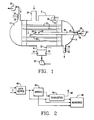
- Figure 1 is a pictorial view illustrating the basic structure of a condenser to be monitored according to the invention.
- FIG. 2 is a block diagram of a system for monitoring a condenser in accordance with the invention.
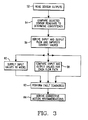
- Figure 3 is a flow diagram illustrating a monitoring operation according to the present invention.
- Figure 1 is a simplified cross-sectional elevational view of a conventional steam plant condenser whose operation may be monitored and controlled according to the invention.
- a condenser performs an indirect heat exchange between steam flowing along a steam flow path from a turbine to a condensate region and cooling water flowing along a cooling water flow path.
- the steam flow path includes a heat exchange region 2 located between a steam inlet 4 and a hot well 6.
- Steam inlet 4 is connected to receive steam of the outlet of the power plant turbine and hot well 6 is connected to return condensate for reuse as boiler feedwater.
- the cooling water path includes an inlet manifold 12, an outlet manifold 14 and a plurality of tubes 16 connecting manifolds 12 and 14 for conveying cooling water through heat exchange region 2.
- Region 2 is separated from manifolds 12 and 14 by suitable partitions.
- Inlet manifold 12 is connected to a cooling water supply via at least one cooling water pump 20 and hot well 6 is connected to a boiler feedwater supply location via at least one condensate pump 22.
- the condenser further includes a system for removing non-condensible components, e.g., air from the heat exchange region 2.
- This system is composed of one or more conduits 26 opening into region 2 on inlet 27 and one or more removal devices, such as a pump 28, at an outlet 29.
- the condenser is equipped with appropriately disposed temperature sensors 30 and pressure sensors 32, as well as at least one chemical sensor 34 for permitting measurement of condensate water quality.
- Heat exchange region 2 is further provided with one or more inlets 36 connected to receive steam or a steam-condensate mixture from bypass lines, drain lines, etc., forming part of the steam flow system.
- FIG. 2 is a block diagram illustrative of a system for processing data produced by sensors 30, 32, 34, as well as other relevant data produced within the power plant, in order to inform supervisory personnel of the condenser operating state and of corrective actions which may be taken.
- This system may be created by programming a general purpose computer or by constructing a dedicated device to include a data buffer 40 connected to receive and temporarily store the data to be processed. This data is supplied at selected intervals to condenser computer models 42, diagnostic units 44 and a subsystem 46 for providing advisories.
- models 42 the anticipated responses of a properly functioning condenser are derived from measured input values and the resulting modeled outputs are compared in diagnostic units 44 with measured condenser output signals from buffer 40. The results of these comparisons can provide signals at an output 48 identifying specific condenser problems and, possibly, their causes. Finally, signals from buffer 40, models 42 and units 44 are supplied to subsystem 46 to permit the generation of operator advisories which inform operating personnel of adjustments which could restore optimum condenser operating conditions or compensate for minor malfunctions or conditions which do not require condenser shut-down. Examples of these functions will be described below.
- a determination of the steam/condensate quantity, or flow, balance can be made by comparing F in with F out , where F in is the mass flow of steam into region 2 via inlets 4 and 36 and F out is the mass flow of condensate out of hot well 6.
- the component of F in associated with inlet 4 can be determined according to techniques currently employed to monitor steam turbine systems. This may be carried out by measurements of the flow of steam into the turbine and of steam extracted from the turbine to heat feedwater.
- the component associated with inlet 36 can be determined by any known technique, such as by installation of a flow meter. F out can be determined by means of a flow meter in the outlet line from hot well 6.
- F in > F out this signifies a buildup of condensate in hot well 6. If the condensate level is observed to be increasing in the hotwell, this increase can be attributed to a failure of the level control system, a possible blockage in the outlet line from hot well 6, or a failure or malfunction of pump 22. On the other hand, if F in > F out and the condensate level is observed to be constant or decreasing, then one or more of the flow measurements is suspect.
- the pressure and temperature measurements at inlet 4 should correspond to those for saturated steam or else the measurements are suspect.
- Q in can be determined as the product of: the temperature difference between water leaving manifold 12 and entering manifold 14; the cooling water flow rate, measured by a flow meter or other technique; and the specific heat of the cooling water.
- Q outst can be determined on the basis of a known function of flow rate, steam quality, and either the temperature or the pressure at inlet.
- Q outcon can be determined as a known function of condensate flow rate and temperature.
- a condition which can have a significant influence on condenser operation is the presence of air in heat exchange region 2 due, for example to leakage from the environment. There, leaks can occur around seals associated with piping into the condenser. A sufficient quality of air in region 2 can form an air layer around tubes 16 or an air bubble, either of which will substantially impair heat transfer between the cooling water and the steam. Moreover, air leaking into region 2 raises the pressure therein.
- the rate at which air flows into region 2 can be determined on the basis of pressure and temperature measurements at inlet 27 and outlet 29 of non-condensible removal line 26.
- the vapor, or steam, partial pressure can be calculated on the basis of its known relation to temperature.
- the air partial pressure at inlet 27 can be determined as the difference between the pressure measured at inlet 27 and the calculated steam vapor pressure corresponding to the temperature at inlet 27.
- the calculated air partial pressure value then can be used to directly determine air content in the gas flow into the non-condensible removal line, from which an inference can be drawn, in units 44, as to the existence and severity of an air leak.
- the molar ratio of air present to the steam is equal to the ratio of air partial pressure to water vapor pressure at inlet 4.
- the magnitude of the air leakage can be determined by monitoring the mass flow rate through conduit 26, which increases in proportion to the quantity of air delivered to region 2.
- Flow is proportional to the square root of the pressure differential between the inlet 27 and outlet 29 of conduit 26, which can be determined on the basis of pressure measurements at those points.
- Flow is also a known function of the energy supplied to, and the pressure rise across, pump or injector 28. Flow values determined by these two procedures can be used to determine consistency of measurements and flow value trends are monitored in units 44 to identify development of leaks.
- a highly reliable manner of detecting leaks between the cooling water flow path and the steam flow path is to monitor dissolved solids, in the form of ions, in the cooling water and in the condensed steam, or feedwater, together with the mass rate of flow of feedwater from hot well 6. Then, the mass rate of leakage flow can be determined as follows: where
- the presence of air leaks can also be indicated by observing the concentration of dissolved oxygen in the condensate in hot well 6.
- concentration of dissolved oxygen in the condensate in hot well 6 For this purpose, the temperature in the hot well is measured, the oxygen partial pressure over the hot well is determined on the basis of its known relation to the oxygen concentration measured in the hot well.
- This oxygen partial pressure can be compared with the non-condensible, air, partial pressure determined at the inlet 27 to the non-condensible removal system 26, 28; presumably this oxygen partial pressure should be significantly less than 1/5 the non-condensible pressure.
- Such information is of importance because dissolved oxygen is a significant cause of corrosion.
- models 42 and units 44 cooperate to provide indications of fouling within conduits 16. Such fouling reduces the rate at which heat can be transferred to the cooling water, by reducing both the heat transfer coefficient associated with the conduit walls and the rate of cooling water flow.
- the occurrence of fouling can be determined by comparing the actual heat transfer coefficient, U act , of conduits 16 with the desired coefficient, U Des , produced in models 42 on the basis of measured values derived when the conduits are known to be free of fouling.
- Changes in the rate of cooling water flow or blockage of flow tubes 16 can also be inferred on the basis of the cooling water pressure differential, ⁇ P, between inlet manifold 12 and outlet manifold 14.
- ⁇ P cooling water pressure differential
- ⁇ P Des a desired value, ⁇ P Des is determined initially in models 42
- the actual value, ⁇ P act is derived continuously on the basis of actual pressure measurement
- the values of the difference ⁇ P act - ⁇ P Des are supplied to units 44 where diagnoses are derived on the basis of the present difference value and changes in the difference value with time.
- the two sets of values described above can also be compared to provide information indicative of instrument consistency.
- An indication of condenser operating effectiveness can be obtained by comparing the backpressure on the turbine, measured at inlet 4, with the optimum value which maximizes a net plant power, i.e., the generator output minus the power input to the condenser system auxiliary pumps and fans.
- Too high a backpressure reduces the expansion ratio of steam in the turbine and correspondingly reduces the power output.
- Too low a backpressure corresponds to high cooling water and non-condensible pumping rates which consume power with no corresponding increase in turbine generator output. Sonic flow in the turbine exhaust limits the effect of lowering backpressure on the power output.
- an indication of low backpressure can produce an advisory to reduce cooling water flow rate and a high backpressure might call for an advisory to increase flow rate.
- the cleanliness of the condenser tubing, the lack of obstructions to water flow, the absence of air and cooling water leaks into condensing region 2 are also important in establishing optimal condenser operation.
- the level of condensate in the hot well 6, the uniformity of temperature there, and the correspondence of temperature with the vaporization temperature corresponding to the condenser pressure is an important indication of optimal, effective condenser operation.
- the hot well water level must be sufficiently high to provide a reservoir of condensate for use as boiler feed water and a head pressure for the condensate pump suction, but sufficiently low to prevent submergence of or splashing on condenser tubing.
- the condensate temperature should be close to the saturation value. (Higher temperature are technically impossible.) Lower temperature values indicate excessive cooling of the condensate and usage of cooling water in various regions of the condenser, requiring additional heat to preheat the condensate.
- models 42 and units 44 are employed to provide indications of the operating states of pumps or ejectors, 20, 22 and 28. For each of these devices, measurements are made of fluid flow, inlet-outlet pressure differential, work, or energy, supplied to the device, and inlet-outlet temperature differential. These measurements can be combined according to known relationships, and the results compared, to provide indications of the consistency of sensor readings and of device malfunctions.
- the flow, pressure differential, and work values at a given time can be compared with pump curves to determine whether the pump performance is deteriorating due to impeller wear, deposit formation, or liquid cavitation.
- the temperature differential across the pump can be compared to that predicted by the energy balance and the measured work input to the pump to determine whether pump, bearing, or motor problems are developing.
- Sensor consistency indications can also be provided by effecting appropriate comparisons between the values provided by pressure drop sensors and flow rate sensors in various connecting lines.
- Equipment malfunction indications can further be provided by appropriate comparisons between measured flow rate, pressure drop and temperature differential values associated with various bypass paths of the condenser system.
- the condenser backpressure i.e., the pressure at inlet 4
- units 44 can respond to a deviation of that pressure from its optimum value together with other indications of equipment faults, e.g., leaks or tube fouling, to arrive at a diagnosis of the probable cause of such backpressure deviation.
- units 44 will provide signals on output 48 identifying the probable cause and will operate subsystem 46 to produce advisories of appropriate corrective action.
- an advisory may be given that it is advisable to make a temporary correction by increasing the speed of pump 28 or the number of pumps operating in parallel.
- a diagnosis of a water leak can lead to an advisory to increase the degree of water treatment and to inspect and plug tube leaks; and a diagnosis of tube fouling can generate an advisory to increase the speed of pump 20 and/or an advisory that tube fouling has reached a point at which it is economically desirable to perform a cleaning operation.
- FIG. 3 represents a framework for the programming of a general purpose computer to implement the invention.
- the first operation typically, would be the reading of all sensor outputs, as indicated at function block 52.
- function block 54 appropriately selected outputs are compared to determine sensor consistency. This represents a conventional operation employed in expert systems to determine whether, and to what extent, reliance can be placed on individual sensor readings.
- the sensor outputs are combined on the basis of known relationships to derive input and output flow and impurity content values for each flow path.
- impurities would include dissolved solids and/or ions.
- function block 58 input and output values for each flow path are compared. These input and output values include not only flow values, but also pressure and temperature values which serve to provide heat transfer information.
- function block 60 sensed and/or derived input values are supplied to the condenser model which produces output values corresponding to a properly operating system.
- the results obtained in function blocks 56, 58 and 60 are supplied to function block 62, where fault diagnosis is performed. If any fault diagnosis indication is produced, this is supplied to function block 64 which will derive corrective action recommendations based in part on expert knowledge incorporated into the system.
Landscapes
- Engineering & Computer Science (AREA)
- General Engineering & Computer Science (AREA)
- Mechanical Engineering (AREA)
- Physics & Mathematics (AREA)
- Plasma & Fusion (AREA)
- High Energy & Nuclear Physics (AREA)
- Control Of Turbines (AREA)
- Engine Equipment That Uses Special Cycles (AREA)
- Testing And Monitoring For Control Systems (AREA)
- Monitoring And Testing Of Nuclear Reactors (AREA)
Applications Claiming Priority (2)
| Application Number | Priority Date | Filing Date | Title |
|---|---|---|---|
| US07/484,750 US5005351A (en) | 1990-02-26 | 1990-02-26 | Power plant condenser control system |
| US484750 | 1995-06-07 |
Publications (2)
| Publication Number | Publication Date |
|---|---|
| EP0444892A2 true EP0444892A2 (de) | 1991-09-04 |
| EP0444892A3 EP0444892A3 (en) | 1992-03-11 |
Family
ID=23925450
Family Applications (1)
| Application Number | Title | Priority Date | Filing Date |
|---|---|---|---|
| EP19910301567 Withdrawn EP0444892A3 (en) | 1990-02-26 | 1991-02-26 | Power plant condenser control system |
Country Status (4)
| Country | Link |
|---|---|
| US (1) | US5005351A (de) |
| EP (1) | EP0444892A3 (de) |
| JP (1) | JPH04217786A (de) |
| KR (1) | KR920005799A (de) |
Cited By (2)
| Publication number | Priority date | Publication date | Assignee | Title |
|---|---|---|---|---|
| WO2001001212A1 (en) * | 1999-06-23 | 2001-01-04 | Saab Ab | A method of supervising or controlling a device by means of a computer model |
| RU2450131C2 (ru) * | 2010-04-06 | 2012-05-10 | Государственное образовательное учреждение высшего профессионального образования Самарский государственный технический университет | Тепловая электрическая станция |
Families Citing this family (24)
| Publication number | Priority date | Publication date | Assignee | Title |
|---|---|---|---|---|
| US6588499B1 (en) * | 1998-11-13 | 2003-07-08 | Pacificorp | Air ejector vacuum control valve |
| US6128905A (en) * | 1998-11-13 | 2000-10-10 | Pacificorp | Back pressure optimizer |
| US6128901A (en) * | 1999-11-01 | 2000-10-10 | Sha; William T. | Pressure control system to improve power plant efficiency |
| US7162873B2 (en) * | 2001-03-16 | 2007-01-16 | Mikhail Levitin | Method of running a condenser for liquidation of steam or vapor |
| US6526755B1 (en) * | 2001-05-07 | 2003-03-04 | Joseph W. C. Harpster | Condensers and their monitoring |
| DE10302156A1 (de) * | 2003-01-21 | 2004-08-05 | Siemens Ag | Anordnung und Verfahren zur Diagnose von Verstopfungen in Kanälen eines Mikrowärmeübertragers |
| US7455099B2 (en) * | 2003-12-19 | 2008-11-25 | General Electric Company | Heat exchanger performance monitoring and analysis method and system |
| CN100351604C (zh) * | 2005-03-08 | 2007-11-28 | 大连理工大学 | 智能控制的热交换器 |
| DE102005043952A1 (de) * | 2005-09-15 | 2007-04-05 | Danfoss A/S | Wärmetauscher und Verfahren zum Regeln eines Wärmetauschers |
| DE102008057202A1 (de) * | 2008-11-13 | 2010-05-20 | Daimler Ag | Clausius-Rankine-Kreis |
| US7802430B1 (en) | 2009-03-20 | 2010-09-28 | Sha William T | Condensers efficiency through novel PCS technology |
| US8100580B2 (en) * | 2009-04-22 | 2012-01-24 | General Electric Company | Measurement of steam quality in steam turbine |
| US20120199310A1 (en) * | 2009-07-07 | 2012-08-09 | A-Heat Allied Heat Exchange Technology Ag | Heat exchange system, as well as a method for the operation of a heat exchange system |
| JP2011191006A (ja) * | 2010-03-15 | 2011-09-29 | Tlv Co Ltd | 熱交換器 |
| JP2013002712A (ja) * | 2011-06-15 | 2013-01-07 | Tlv Co Ltd | 廃蒸気回収装置 |
| US9512741B2 (en) * | 2011-08-19 | 2016-12-06 | Fuji Electric Co., Ltd. | Power plant |
| US9298173B2 (en) * | 2012-02-02 | 2016-03-29 | General Electric Company | System and method to performance tune a system |
| JP6501380B2 (ja) * | 2014-07-01 | 2019-04-17 | 三菱重工コンプレッサ株式会社 | 多段圧縮機システム、制御装置、異常判定方法及びプログラム |
| US20160252310A1 (en) * | 2015-02-27 | 2016-09-01 | Tenneco Automotive Operating Company Inc. | Waste Heat Recovery System |
| JP6254968B2 (ja) * | 2015-03-06 | 2017-12-27 | ヤンマー株式会社 | 動力発生装置 |
| BR112019009500A2 (pt) * | 2016-12-21 | 2019-08-06 | Gen Electric | proteção contra corrosão para condensadores resfriados a ar |
| CN110285687B (zh) * | 2019-06-26 | 2020-11-06 | 双良节能系统股份有限公司 | 一种基于人工智能技术的空冷控制系统及其控制方法 |
| CN113035396A (zh) * | 2021-03-05 | 2021-06-25 | 哈尔滨工程大学 | 一种采用双轮双叶复合动力吹气式的安全壳内置高效换热器 |
| US12578154B2 (en) * | 2022-07-27 | 2026-03-17 | Chemtreat, Inc. | Methods and systems for evaluating heat exchangers |
Family Cites Families (4)
| Publication number | Priority date | Publication date | Assignee | Title |
|---|---|---|---|---|
| CH411011A (de) * | 1964-06-12 | 1966-04-15 | Bbc Brown Boveri & Cie | Verfahren und Einrichtung zur Regelung einer Kondensationsanlage |
| JPS5919273B2 (ja) * | 1979-12-05 | 1984-05-04 | 株式会社日立製作所 | 復水器性能監視方法 |
| JPS60218585A (ja) * | 1984-04-13 | 1985-11-01 | Hitachi Ltd | 復水器脱気蒸気系統の制御装置 |
| US4768346A (en) * | 1987-08-26 | 1988-09-06 | Honeywell Inc. | Determining the coefficient of performance of a refrigeration system |
-
1990
- 1990-02-26 US US07/484,750 patent/US5005351A/en not_active Expired - Fee Related
-
1991
- 1991-02-25 KR KR1019910003049A patent/KR920005799A/ko not_active Withdrawn
- 1991-02-26 JP JP3030794A patent/JPH04217786A/ja active Pending
- 1991-02-26 EP EP19910301567 patent/EP0444892A3/en not_active Withdrawn
Cited By (2)
| Publication number | Priority date | Publication date | Assignee | Title |
|---|---|---|---|---|
| WO2001001212A1 (en) * | 1999-06-23 | 2001-01-04 | Saab Ab | A method of supervising or controlling a device by means of a computer model |
| RU2450131C2 (ru) * | 2010-04-06 | 2012-05-10 | Государственное образовательное учреждение высшего профессионального образования Самарский государственный технический университет | Тепловая электрическая станция |
Also Published As
| Publication number | Publication date |
|---|---|
| EP0444892A3 (en) | 1992-03-11 |
| KR920005799A (ko) | 1992-04-03 |
| JPH04217786A (ja) | 1992-08-07 |
| US5005351A (en) | 1991-04-09 |
Similar Documents
| Publication | Publication Date | Title |
|---|---|---|
| US5005351A (en) | Power plant condenser control system | |
| US5794446A (en) | Power plant performance management systems and methods | |
| US4833622A (en) | Intelligent chemistry management system | |
| US10663162B2 (en) | Fluid utilization facility management method and fluid utilization facility management system | |
| US5083606A (en) | Structure and method for on-line inspection of condenser tubes | |
| US5791147A (en) | Power plant performance management systems and methods | |
| CN111537257B (zh) | 一种在线检测水轮发电机空气冷却器异常方法 | |
| US5060600A (en) | Condenser operation with isolated on-line test loop | |
| CN114839339A (zh) | 一种监测发电机定冷水漏氢量的方法和系统 | |
| JP3070999B2 (ja) | プラントの水質診断装置 | |
| CN114970136B (zh) | 一种核电厂除氧器的抽汽质量流量实时确定方法及设备 | |
| CN214792725U (zh) | 一种工业冷却循环水监控模拟换热器在线监控装置 | |
| JP3758465B2 (ja) | 復水器,発電プラント設備、及びその運転方法 | |
| Aronson et al. | An expert system for diagnostics and estimation of steam turbine components’ condition | |
| KR100958939B1 (ko) | 연료가스의 습분감시장치 및 습분감시방법 | |
| CN114943175A (zh) | 一种电厂设备测点健康基准值的预测方法及系统 | |
| CN108257694B (zh) | 一种核电站主给水系统性能监督方法 | |
| Murmanskii et al. | Features of steam turbines diagnostics | |
| JPS5857008A (ja) | 給水ポンプ及び同駆動タ−ビンの異常診断方法 | |
| Sultanov et al. | Assessment of technical condition of condensers of TPP steam turbines according to the data of the power equipment parameters monitoring system | |
| JP2015224865A (ja) | 蒸気使用設備の監視システム | |
| Piyushsinh | Application of monitoring approaches on steam turbine of thermal power plant for better performance | |
| KR102345245B1 (ko) | 원전 시설의 감시 진단 시스템 및 방법 | |
| CN121025374A (zh) | 一种用于监控火力发电厂热力管道安全运行的智能系统 | |
| JPH0682004A (ja) | 給水加熱器の管漏洩診断装置 |
Legal Events
| Date | Code | Title | Description |
|---|---|---|---|
| PUAI | Public reference made under article 153(3) epc to a published international application that has entered the european phase |
Free format text: ORIGINAL CODE: 0009012 |
|
| AK | Designated contracting states |
Kind code of ref document: A2 Designated state(s): BE CH ES FR GB IT LI |
|
| PUAL | Search report despatched |
Free format text: ORIGINAL CODE: 0009013 |
|
| STAA | Information on the status of an ep patent application or granted ep patent |
Free format text: STATUS: THE APPLICATION HAS BEEN WITHDRAWN |
|
| AK | Designated contracting states |
Kind code of ref document: A3 Designated state(s): BE CH ES FR GB IT LI |
|
| 18W | Application withdrawn |
Withdrawal date: 19920204 |