EP0444575B1 - Abgeschirmter magnetoelastischer Drehmomentwandler - Google Patents
Abgeschirmter magnetoelastischer Drehmomentwandler Download PDFInfo
- Publication number
- EP0444575B1 EP0444575B1 EP91102738A EP91102738A EP0444575B1 EP 0444575 B1 EP0444575 B1 EP 0444575B1 EP 91102738 A EP91102738 A EP 91102738A EP 91102738 A EP91102738 A EP 91102738A EP 0444575 B1 EP0444575 B1 EP 0444575B1
- Authority
- EP
- European Patent Office
- Prior art keywords
- shaft
- transducer
- magnetic
- shield
- flanges
- Prior art date
- Legal status (The legal status is an assumption and is not a legal conclusion. Google has not performed a legal analysis and makes no representation as to the accuracy of the status listed.)
- Expired - Lifetime
Links
- 230000005291 magnetic effect Effects 0.000 claims description 31
- 239000000696 magnetic material Substances 0.000 claims description 11
- 230000003068 static effect Effects 0.000 claims description 9
- 238000004804 winding Methods 0.000 claims description 4
- 230000005284 excitation Effects 0.000 claims description 2
- 230000004907 flux Effects 0.000 description 7
- 230000005415 magnetization Effects 0.000 description 5
- 239000000463 material Substances 0.000 description 4
- 238000005259 measurement Methods 0.000 description 4
- 230000000694 effects Effects 0.000 description 3
- 238000000034 method Methods 0.000 description 3
- 230000035699 permeability Effects 0.000 description 3
- 230000005540 biological transmission Effects 0.000 description 2
- 239000003302 ferromagnetic material Substances 0.000 description 2
- 230000035945 sensitivity Effects 0.000 description 2
- 238000013459 approach Methods 0.000 description 1
- 238000013461 design Methods 0.000 description 1
- 230000001627 detrimental effect Effects 0.000 description 1
- 238000011161 development Methods 0.000 description 1
- 230000018109 developmental process Effects 0.000 description 1
- 238000010291 electrical method Methods 0.000 description 1
- 229910000595 mu-metal Inorganic materials 0.000 description 1
Images
Classifications
-
- G—PHYSICS
- G01—MEASURING; TESTING
- G01L—MEASURING FORCE, STRESS, TORQUE, WORK, MECHANICAL POWER, MECHANICAL EFFICIENCY, OR FLUID PRESSURE
- G01L3/00—Measuring torque, work, mechanical power, or mechanical efficiency, in general
- G01L3/02—Rotary-transmission dynamometers
- G01L3/04—Rotary-transmission dynamometers wherein the torque-transmitting element comprises a torsionally-flexible shaft
- G01L3/10—Rotary-transmission dynamometers wherein the torque-transmitting element comprises a torsionally-flexible shaft involving electric or magnetic means for indicating
- G01L3/101—Rotary-transmission dynamometers wherein the torque-transmitting element comprises a torsionally-flexible shaft involving electric or magnetic means for indicating involving magnetic or electromagnetic means
- G01L3/102—Rotary-transmission dynamometers wherein the torque-transmitting element comprises a torsionally-flexible shaft involving electric or magnetic means for indicating involving magnetic or electromagnetic means involving magnetostrictive means
-
- G—PHYSICS
- G01—MEASURING; TESTING
- G01L—MEASURING FORCE, STRESS, TORQUE, WORK, MECHANICAL POWER, MECHANICAL EFFICIENCY, OR FLUID PRESSURE
- G01L3/00—Measuring torque, work, mechanical power, or mechanical efficiency, in general
- G01L3/02—Rotary-transmission dynamometers
- G01L3/04—Rotary-transmission dynamometers wherein the torque-transmitting element comprises a torsionally-flexible shaft
- G01L3/10—Rotary-transmission dynamometers wherein the torque-transmitting element comprises a torsionally-flexible shaft involving electric or magnetic means for indicating
- G01L3/101—Rotary-transmission dynamometers wherein the torque-transmitting element comprises a torsionally-flexible shaft involving electric or magnetic means for indicating involving magnetic or electromagnetic means
- G01L3/105—Rotary-transmission dynamometers wherein the torque-transmitting element comprises a torsionally-flexible shaft involving electric or magnetic means for indicating involving magnetic or electromagnetic means involving inductive means
-
- Y—GENERAL TAGGING OF NEW TECHNOLOGICAL DEVELOPMENTS; GENERAL TAGGING OF CROSS-SECTIONAL TECHNOLOGIES SPANNING OVER SEVERAL SECTIONS OF THE IPC; TECHNICAL SUBJECTS COVERED BY FORMER USPC CROSS-REFERENCE ART COLLECTIONS [XRACs] AND DIGESTS
- Y10—TECHNICAL SUBJECTS COVERED BY FORMER USPC
- Y10T—TECHNICAL SUBJECTS COVERED BY FORMER US CLASSIFICATION
- Y10T29/00—Metal working
- Y10T29/49—Method of mechanical manufacture
- Y10T29/49002—Electrical device making
- Y10T29/4902—Electromagnet, transformer or inductor
Definitions
- the invention relates to a shielded magnetoelastic torque transducer according to the precharacterising part of claim 1. Shielding is provided against static or quasistatic magnetic fields axially extending in the shaft between the driving source and the driven load.
- magnetoelastic transducers are based on the measurement of the permeability change which takes place in a ferromagnetic material when subjected to mechanical stress.
- the measuring principles and configuration of these transducers are well known and described in a plurality of publications and patent specifications, inter alia in EP-A-89,916, US-A-4,506,554 and SE-A-8,904,307-9, the latter corresponding to EP-A-90,195,168.6.
- a magnetoelastic torque transducer comprises a transducer shaft and a stationary casing comprising a magnetic core as well as excitation and measuring windings attached to said core. A detailed description thereof need not be given here.
- the magnetic hysteresis curve that is, the flux-density-versa-magnetic-field-strength-curve (B-H curve), traversed by each point in the material during a cycle of the magnetization, will be changed when the material is, in addition, magnetized by a static field.
- B-H curve flux-density-versa-magnetic-field-strength-curve
- the differential permeability as well as the sensitivity of the transducer will be very low. However, the detrimental influence is also present in connection with considerably lower field strengths.
- the traditional method is to surround the transducer with a magnetic shield made of highly magnetically permeable material, for example of mu-metal (see e.g. published utility model DE-U- 8 903 560).
- a magnetic shield made of highly magnetically permeable material, for example of mu-metal (see e.g. published utility model DE-U- 8 903 560).
- mu-metal see e.g. published utility model DE-U- 8 903 560.
- such a design mainly serves as a shield against magnetic fields in the air which are directed across the transducer shaft.
- a torque transducer forms a link in a torque transmission between a driving source and a load.
- a remanent axial magnetic field in some of the parts in this transmission may then be conducted directly into the transducer shaft without being diverted by the external shield.
- the above-mentioned SE-A-8,904,307-9 discloses an electrical method of minimizing the effect of an external static or quasi-static magnetic field.
- the method is based on the fact that an external magnetic field causes the measured signal to comprise even harmonics, together with the odd harmonics of the fundamental wave of the magnetization.
- the magnitude of the even harmonics is a measure of the magnitude of the external magnetic field.
- the transducer shaft of magnetic material constitutes part of the magnetic shaft which connects the driving source to the driven load. If in some way a magnetic flux with a component in the longitudinal direction of the shaft may enter the shaft, this flux will therefore also pass through the transducer shaft and is able to influence the torque measurement in the manner described. As explained above, a shield surrounding the transducer will not be able to divert this magnetic flux in the shaft from the transducer.
- the invention aims at developing a shielded magnetoelastic torque transducer of the above-mentioned kind which is capable to shield off external magnetic fields that extend in the longitudinal direction within the shafts connected to the torque transducer.
- the invention suggests a shielded magnetoelastic torque transducer according to the introductory part of claim 1, which is characterized by the features of the characterizing part of claim 1.
- the driving shaft between the driving source and the load is divided in such a way that the part between the driving source and the transducer shaft and part between the transducer shaft and the load, respectively, are made of non-magnetic material.
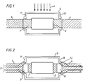
- Figure 1 shows an example of the state of the art such as detailed in DE-U- 8 903 560 for protecting a torque transducer against an external magnetic field 6 present in the ambient space and directed perpendicular to the transducer shaft.
- the transducer shaft 1 is surrounded by a stationary casing 2 of the transducer which houses the windings etc. Welded or otherwise fixed to one end of the transducer shaft is a first shaft part 3 towards a driving source, and, in similar manner, fixed to the other end of the transducer shaft is a second shaft part 4 towards the driven load.
- a soft-magnetic shield 5 then protects the transducer against the external magnetic field 6 directed perpendicular to the transducer shaft.
- FIG. 2 shows a transducer shaft, a casing 2, shaft parts 3 and 4 towards the driving source and towards the driven load, respectively, and a surrounding magnetic shield 5.
- a transducer shaft and the previously mentioned first shaft part 3 towards the driving source and between the transducer shaft and the previously mentioned second shaft part 4 towards the driven load respectively, a third shaft part 7 and a fourth shaft part 8, respectively, of non-magnetic material are inserted.
- the flanges 10, 11 are located opposite the shaft parts 7, 8 of non-magnetic material.
- the effect of the short-circuiting function of the shield 5 with its flanges may be further increased by locating the flanges such that they face portions of the shaft parts 3 and 4, respectively, of magnetic material.
Landscapes
- Physics & Mathematics (AREA)
- Electromagnetism (AREA)
- General Physics & Mathematics (AREA)
- Shafts, Cranks, Connecting Bars, And Related Bearings (AREA)
- Force Measurement Appropriate To Specific Purposes (AREA)
- Details Of Measuring And Other Instruments (AREA)
- Transmission And Conversion Of Sensor Element Output (AREA)
Claims (4)
- Magneto-elastischer Drehmomentengeber, der gegen statische oder quasistatische äußere magnetische Felder abgeschirmt ist, mit einem stationären Gehäuse (2), in welchem ein magnetischer Kern mit Erreger- und Meßwicklungen und eine Geberwelle (1) untergebracht sind, mit einem ersten Wellenabschnitt (3) zwischen der genannten Geberwelle und einer Antriebsquelle und mit einem zweiten Wellenabschnitt (4) zwischen der genannnten Geberwelle und einer angetriebenen Last, wobei das genannte Gehäuse und die Welle von einem magnetischen Schild aus weich-magnetischem Material umgeben ist, welches mit Flanschen (10,11) versehen ist, die sich zu der Welle erstrecken, dadurch gekennzeichnet, daß zwischen der Geberwelle und dem ersten Wellenabschnitt (3) ein dritter Wellenabschnitt (7) aus nicht-magnetischem Material eingefügt ist, daß zwischen der Geberwelle und dem zweiten Wellenabschnitt (4) ein vierter Wellenabschnitt (8) aus nicht-magnetischem Material eingefügt ist und daß das Gehäuse (2), die Geberwelle und die aus nicht-magnetischem Material bestehenden Wellenabschnitten (7,8) von dem genannten magnetischen Schild (5) umgeben sind.
- Abgeschirmter magneto-elastischer Drehmomentengeber nach Anspruch 1, dadurch gekennzeichnet, daß die Luftspalte (12) zwischen den Flanschen (10,11) des Schildes und der Welle so klein wie möglich sind.
- Abgeschirmter magneto-elastischer Drehmomentengeber nach Anspruch 1 oder 2, dadurch gekennzeichnet, daß der Schild (5) und/oder seine Flansche (10,11) derart geformt und bemessen sind, daß die Luftspalte (12) zwischen den genannten Flanschen und den Wellenabschnitten (7,8) aus nicht-magnetischem Material liegen.
- Abgeschirmter magneto-elastischer Drehmomentengeber nach Anspruch 1 oder 2, dadurch gekennzeichnet, daß der Schild (5) und/oder seine Flansche (10,11) derart geformt und bemessen sind, daß die Luftspalte (12) vorhanden sind zwischen den genannten Flanschen (10,11) und dem ersten Wellenabschnitt (3), der zwischen dem Wellenabschnitt (7) aus nicht-magnetischem Material und der Antriebsquelle liegt, beziehungsweise dem zweiten Wellenabschnitt (4), der zwischen dem Wellenabschnitt (8) aus nicht-magnetischem Material und der Last liegt.
Applications Claiming Priority (2)
| Application Number | Priority Date | Filing Date | Title |
|---|---|---|---|
| SE9000716A SE465942B (sv) | 1990-02-28 | 1990-02-28 | Foerfarande foer att skaerma magnetoelastiska givare |
| SE9000716 | 1990-02-28 |
Publications (3)
| Publication Number | Publication Date |
|---|---|
| EP0444575A2 EP0444575A2 (de) | 1991-09-04 |
| EP0444575A3 EP0444575A3 (en) | 1992-06-03 |
| EP0444575B1 true EP0444575B1 (de) | 1994-12-14 |
Family
ID=20378717
Family Applications (1)
| Application Number | Title | Priority Date | Filing Date |
|---|---|---|---|
| EP91102738A Expired - Lifetime EP0444575B1 (de) | 1990-02-28 | 1991-02-25 | Abgeschirmter magnetoelastischer Drehmomentwandler |
Country Status (5)
| Country | Link |
|---|---|
| US (1) | US5083359A (de) |
| EP (1) | EP0444575B1 (de) |
| JP (1) | JP3110774B2 (de) |
| DE (1) | DE69105775T2 (de) |
| SE (1) | SE465942B (de) |
Families Citing this family (12)
| Publication number | Priority date | Publication date | Assignee | Title |
|---|---|---|---|---|
| US5255567A (en) * | 1990-06-30 | 1993-10-26 | Nippon Densan Corporation | Torque transducer |
| US5889215A (en) * | 1996-12-04 | 1999-03-30 | Philips Electronics North America Corporation | Magnetoelastic torque sensor with shielding flux guide |
| KR100500560B1 (ko) | 1997-03-28 | 2005-07-12 | 만네스만 파우데오 아게 | 자기탄성 트랜스듀서 제조 방법 |
| US6105236A (en) * | 1998-02-05 | 2000-08-22 | Raytheon Company | Magnetic structure for minimizing AC resistance in planar rectangular conductors |
| JP4516281B2 (ja) * | 2003-04-02 | 2010-08-04 | 本田技研工業株式会社 | トルクセンサ |
| JP2005043160A (ja) * | 2003-07-25 | 2005-02-17 | Hitachi Unisia Automotive Ltd | 回転検出センサ |
| JP2007121149A (ja) * | 2005-10-28 | 2007-05-17 | Jtekt Corp | トルク検出装置 |
| DE102006044779B4 (de) * | 2006-09-22 | 2009-08-20 | Continental Automotive Gmbh | Vorrichtung zur Erfassung einer Kraft und/oder eines Drehmoments |
| CA2718284C (en) | 2008-03-14 | 2017-02-07 | Seong-Jae Lee | Magnetoelastic torque sensor with ambient field rejection |
| US8001849B2 (en) * | 2009-03-28 | 2011-08-23 | Wensheng Weng | Self-compensating magnetoelastic torque sensor system |
| AU2013200469B2 (en) * | 2012-02-07 | 2016-03-24 | Methode Electronics, Inc. | Magnetic torque sensor for transmission converter drive plate |
| CN106737202A (zh) * | 2016-12-26 | 2017-05-31 | 株洲九方装备股份有限公司 | 一种含有永磁体工件的机加工磁场屏蔽方法及装置 |
Family Cites Families (3)
| Publication number | Priority date | Publication date | Assignee | Title |
|---|---|---|---|---|
| JPS58159720A (ja) * | 1982-03-19 | 1983-09-22 | オリンパス光学工業株式会社 | 内視鏡用水漏検出装置 |
| JPS61247932A (ja) * | 1985-04-26 | 1986-11-05 | Matsushita Electric Ind Co Ltd | トルクセンサ |
| DE8903560U1 (de) * | 1989-03-21 | 1989-05-18 | Siemens AG, 1000 Berlin und 8000 München | Drehmoment-Meßsensor |
-
1990
- 1990-02-28 SE SE9000716A patent/SE465942B/sv not_active IP Right Cessation
-
1991
- 1991-02-25 DE DE69105775T patent/DE69105775T2/de not_active Expired - Fee Related
- 1991-02-25 EP EP91102738A patent/EP0444575B1/de not_active Expired - Lifetime
- 1991-02-26 US US07/660,844 patent/US5083359A/en not_active Expired - Lifetime
- 1991-02-27 JP JP03033038A patent/JP3110774B2/ja not_active Expired - Fee Related
Also Published As
| Publication number | Publication date |
|---|---|
| US5083359A (en) | 1992-01-28 |
| DE69105775T2 (de) | 1995-07-27 |
| SE465942B (sv) | 1991-11-18 |
| SE9000716D0 (sv) | 1990-02-28 |
| JPH04216428A (ja) | 1992-08-06 |
| EP0444575A3 (en) | 1992-06-03 |
| DE69105775D1 (de) | 1995-01-26 |
| EP0444575A2 (de) | 1991-09-04 |
| SE9000716L (sv) | 1991-08-29 |
| JP3110774B2 (ja) | 2000-11-20 |
Similar Documents
| Publication | Publication Date | Title |
|---|---|---|
| US4045738A (en) | Variable reluctance speed sensor of integral construction utilizing a shielded high coercive force rare earth magnet positioned directly adjacent the sensing rotating element | |
| EP0444575B1 (de) | Abgeschirmter magnetoelastischer Drehmomentwandler | |
| EP1070237B1 (de) | Magnetischer kraftsensor und verfahren zu dessen herstellung | |
| US5465627A (en) | Circularly magnetized non-contact torque sensor and method for measuring torque using same | |
| US4150314A (en) | Level amplitude output rotary speed transducer | |
| EP0829001B1 (de) | Zirkular magnetisierter kontaktloser sensor zur messung von drehmoment und leistung und verfahren zur messung von drehmoment und leistung mit diesem sensor | |
| US8893562B2 (en) | System and method for detecting magnetic noise by applying a switching function to magnetic field sensing coils | |
| US3932813A (en) | Eddy current sensor | |
| EP2260278B1 (de) | Magnetoelastischer drehmomentsensor mit umgebungsfeldzurückweisung | |
| US4986137A (en) | Strain detector with magnetostrictive elements | |
| US4891992A (en) | Torque detecting apparatus | |
| US7584672B2 (en) | Magnetostrictive torque sensor | |
| JPH01187424A (ja) | トルクセンサ | |
| EP0435232A1 (de) | Verschiebungssensor vom Induktionstyp mit Unempfindlichkeit gegenüber externen magnetischen Feldern | |
| US4651573A (en) | Shaft torquemeter | |
| JP2608498B2 (ja) | 磁歪式トルクセンサ | |
| JP2566640B2 (ja) | トルク測定装置 | |
| JP2000009557A (ja) | トルクセンサ | |
| JPH1194658A (ja) | トルクセンサ | |
| Sasada et al. | A new method of assembling a torque transducer by the use of bilayer-structure amorphous ribbons | |
| JPH02154130A (ja) | 歪検出器 | |
| JPH02281116A (ja) | 歪検出装置 | |
| JPS61294322A (ja) | トルク検出装置 | |
| JPH0454322A (ja) | 磁性粒子式電磁連結装置 | |
| JPS6050429A (ja) | トルクセンサ |
Legal Events
| Date | Code | Title | Description |
|---|---|---|---|
| PUAI | Public reference made under article 153(3) epc to a published international application that has entered the european phase |
Free format text: ORIGINAL CODE: 0009012 |
|
| AK | Designated contracting states |
Kind code of ref document: A2 Designated state(s): DE FR GB IT |
|
| PUAL | Search report despatched |
Free format text: ORIGINAL CODE: 0009013 |
|
| AK | Designated contracting states |
Kind code of ref document: A3 Designated state(s): DE FR GB IT |
|
| 17P | Request for examination filed |
Effective date: 19921127 |
|
| 17Q | First examination report despatched |
Effective date: 19940203 |
|
| GRAA | (expected) grant |
Free format text: ORIGINAL CODE: 0009210 |
|
| AK | Designated contracting states |
Kind code of ref document: B1 Designated state(s): DE FR GB IT |
|
| REF | Corresponds to: |
Ref document number: 69105775 Country of ref document: DE Date of ref document: 19950126 |
|
| ITF | It: translation for a ep patent filed | ||
| ET | Fr: translation filed | ||
| PLBE | No opposition filed within time limit |
Free format text: ORIGINAL CODE: 0009261 |
|
| STAA | Information on the status of an ep patent application or granted ep patent |
Free format text: STATUS: NO OPPOSITION FILED WITHIN TIME LIMIT |
|
| 26N | No opposition filed | ||
| REG | Reference to a national code |
Ref country code: GB Ref legal event code: IF02 |
|
| PGFP | Annual fee paid to national office [announced via postgrant information from national office to epo] |
Ref country code: DE Payment date: 20090219 Year of fee payment: 19 |
|
| PGFP | Annual fee paid to national office [announced via postgrant information from national office to epo] |
Ref country code: GB Payment date: 20090225 Year of fee payment: 19 |
|
| PGFP | Annual fee paid to national office [announced via postgrant information from national office to epo] |
Ref country code: IT Payment date: 20090218 Year of fee payment: 19 |
|
| PGFP | Annual fee paid to national office [announced via postgrant information from national office to epo] |
Ref country code: FR Payment date: 20090213 Year of fee payment: 19 |
|
| GBPC | Gb: european patent ceased through non-payment of renewal fee |
Effective date: 20100225 |
|
| REG | Reference to a national code |
Ref country code: FR Ref legal event code: ST Effective date: 20101029 |
|
| PG25 | Lapsed in a contracting state [announced via postgrant information from national office to epo] |
Ref country code: FR Free format text: LAPSE BECAUSE OF NON-PAYMENT OF DUE FEES Effective date: 20100301 |
|
| PG25 | Lapsed in a contracting state [announced via postgrant information from national office to epo] |
Ref country code: DE Free format text: LAPSE BECAUSE OF NON-PAYMENT OF DUE FEES Effective date: 20100901 |
|
| PG25 | Lapsed in a contracting state [announced via postgrant information from national office to epo] |
Ref country code: IT Free format text: LAPSE BECAUSE OF NON-PAYMENT OF DUE FEES Effective date: 20100225 Ref country code: GB Free format text: LAPSE BECAUSE OF NON-PAYMENT OF DUE FEES Effective date: 20100225 |