EP0444313A2 - Valve body - Google Patents
Valve body Download PDFInfo
- Publication number
- EP0444313A2 EP0444313A2 EP90125625A EP90125625A EP0444313A2 EP 0444313 A2 EP0444313 A2 EP 0444313A2 EP 90125625 A EP90125625 A EP 90125625A EP 90125625 A EP90125625 A EP 90125625A EP 0444313 A2 EP0444313 A2 EP 0444313A2
- Authority
- EP
- European Patent Office
- Prior art keywords
- valve body
- particular according
- valve
- neck
- adapter
- Prior art date
- Legal status (The legal status is an assumption and is not a legal conclusion. Google has not performed a legal analysis and makes no representation as to the accuracy of the status listed.)
- Withdrawn
Links
Images


Classifications
-
- B—PERFORMING OPERATIONS; TRANSPORTING
- B05—SPRAYING OR ATOMISING IN GENERAL; APPLYING FLUENT MATERIALS TO SURFACES, IN GENERAL
- B05B—SPRAYING APPARATUS; ATOMISING APPARATUS; NOZZLES
- B05B11/00—Single-unit hand-held apparatus in which flow of contents is produced by the muscular force of the operator at the moment of use
- B05B11/01—Single-unit hand-held apparatus in which flow of contents is produced by the muscular force of the operator at the moment of use characterised by the means producing the flow
- B05B11/04—Deformable containers producing the flow, e.g. squeeze bottles
- B05B11/048—Deformable containers producing the flow, e.g. squeeze bottles characterised by the container, e.g. this latter being surrounded by an enclosure, or the means for deforming it
-
- B—PERFORMING OPERATIONS; TRANSPORTING
- B05—SPRAYING OR ATOMISING IN GENERAL; APPLYING FLUENT MATERIALS TO SURFACES, IN GENERAL
- B05B—SPRAYING APPARATUS; ATOMISING APPARATUS; NOZZLES
- B05B11/00—Single-unit hand-held apparatus in which flow of contents is produced by the muscular force of the operator at the moment of use
- B05B11/01—Single-unit hand-held apparatus in which flow of contents is produced by the muscular force of the operator at the moment of use characterised by the means producing the flow
- B05B11/04—Deformable containers producing the flow, e.g. squeeze bottles
- B05B11/047—Deformable containers producing the flow, e.g. squeeze bottles characterised by the outlet or venting means
-
- B—PERFORMING OPERATIONS; TRANSPORTING
- B65—CONVEYING; PACKING; STORING; HANDLING THIN OR FILAMENTARY MATERIAL
- B65D—CONTAINERS FOR STORAGE OR TRANSPORT OF ARTICLES OR MATERIALS, e.g. BAGS, BARRELS, BOTTLES, BOXES, CANS, CARTONS, CRATES, DRUMS, JARS, TANKS, HOPPERS, FORWARDING CONTAINERS; ACCESSORIES, CLOSURES, OR FITTINGS THEREFOR; PACKAGING ELEMENTS; PACKAGES
- B65D47/00—Closures with filling and discharging, or with discharging, devices
- B65D47/04—Closures with discharging devices other than pumps
- B65D47/20—Closures with discharging devices other than pumps comprising hand-operated members for controlling discharge
- B65D47/2018—Closures with discharging devices other than pumps comprising hand-operated members for controlling discharge comprising a valve or like element which is opened or closed by deformation of the container or closure
-
- B—PERFORMING OPERATIONS; TRANSPORTING
- B65—CONVEYING; PACKING; STORING; HANDLING THIN OR FILAMENTARY MATERIAL
- B65D—CONTAINERS FOR STORAGE OR TRANSPORT OF ARTICLES OR MATERIALS, e.g. BAGS, BARRELS, BOTTLES, BOXES, CANS, CARTONS, CRATES, DRUMS, JARS, TANKS, HOPPERS, FORWARDING CONTAINERS; ACCESSORIES, CLOSURES, OR FITTINGS THEREFOR; PACKAGING ELEMENTS; PACKAGES
- B65D83/00—Containers or packages with special means for dispensing contents
- B65D83/771—Containers or packages with special means for dispensing contents for dispensing fluent contents by means of a flexible bag or a deformable membrane or diaphragm
-
- F—MECHANICAL ENGINEERING; LIGHTING; HEATING; WEAPONS; BLASTING
- F16—ENGINEERING ELEMENTS AND UNITS; GENERAL MEASURES FOR PRODUCING AND MAINTAINING EFFECTIVE FUNCTIONING OF MACHINES OR INSTALLATIONS; THERMAL INSULATION IN GENERAL
- F16K—VALVES; TAPS; COCKS; ACTUATING-FLOATS; DEVICES FOR VENTING OR AERATING
- F16K15/00—Check valves
- F16K15/14—Check valves with flexible valve members
- F16K15/1402—Check valves with flexible valve members having an integral flexible member cooperating with a plurality of seating surfaces
-
- F—MECHANICAL ENGINEERING; LIGHTING; HEATING; WEAPONS; BLASTING
- F16—ENGINEERING ELEMENTS AND UNITS; GENERAL MEASURES FOR PRODUCING AND MAINTAINING EFFECTIVE FUNCTIONING OF MACHINES OR INSTALLATIONS; THERMAL INSULATION IN GENERAL
- F16K—VALVES; TAPS; COCKS; ACTUATING-FLOATS; DEVICES FOR VENTING OR AERATING
- F16K15/00—Check valves
- F16K15/14—Check valves with flexible valve members
- F16K15/16—Check valves with flexible valve members with tongue-shaped laminae
-
- Y—GENERAL TAGGING OF NEW TECHNOLOGICAL DEVELOPMENTS; GENERAL TAGGING OF CROSS-SECTIONAL TECHNOLOGIES SPANNING OVER SEVERAL SECTIONS OF THE IPC; TECHNICAL SUBJECTS COVERED BY FORMER USPC CROSS-REFERENCE ART COLLECTIONS [XRACs] AND DIGESTS
- Y10—TECHNICAL SUBJECTS COVERED BY FORMER USPC
- Y10T—TECHNICAL SUBJECTS COVERED BY FORMER US CLASSIFICATION
- Y10T137/00—Fluid handling
- Y10T137/7722—Line condition change responsive valves
- Y10T137/7837—Direct response valves [i.e., check valve type]
- Y10T137/7838—Plural
- Y10T137/7843—Integral resilient member forms plural valves
-
- Y—GENERAL TAGGING OF NEW TECHNOLOGICAL DEVELOPMENTS; GENERAL TAGGING OF CROSS-SECTIONAL TECHNOLOGIES SPANNING OVER SEVERAL SECTIONS OF THE IPC; TECHNICAL SUBJECTS COVERED BY FORMER USPC CROSS-REFERENCE ART COLLECTIONS [XRACs] AND DIGESTS
- Y10—TECHNICAL SUBJECTS COVERED BY FORMER USPC
- Y10T—TECHNICAL SUBJECTS COVERED BY FORMER US CLASSIFICATION
- Y10T137/00—Fluid handling
- Y10T137/7722—Line condition change responsive valves
- Y10T137/7837—Direct response valves [i.e., check valve type]
- Y10T137/7879—Resilient material valve
- Y10T137/7888—With valve member flexing about securement
- Y10T137/7891—Flap or reed
Definitions
- the invention relates to a valve body for a dispenser, in particular a dispenser with a compressible and elastically resilient container and with a self-closing filling material outlet and air inlet valve. Furthermore, the invention relates to a cartridge and a dispenser with a cartridge and a valve body.
- Such a dispenser is known from PCT / CH85 / 00109, in which filling material is pressed through a suction pipe into a valve body by means of a pressure built up in the container and exits the valve body through a filling material outlet valve.
- the pressure is generated by compressing the elastically resilient container. After the compression, the volume of product which has emerged through the outlet valve is replaced by air which can flow into the container through an air inlet valve.
- the object of the invention is to provide a generic valve body which is designed to be advantageous in use and easy to manufacture.
- valve body specified in claim 1 by two interconnectable, in particular latchable, valve body parts which form a separating plane extending in the longitudinal direction of the valve body, namely a closure part and a dispensing opening part, the filling material outlet valve being formed by a closure member which in the region of the separating plane Locking part resilient in the longitudinal direction of the valve body is integrally formed to form a closing support on a valve seat assigned to the dispensing opening part.
- valve body that is particularly easy to produce by injection molding. It only consists of two pluggable valve body parts, which together form the product outlet valve. It is advantageous to form the valve body parts, closure part and dispensing opening part in one piece with one another. The two valve body parts can then be produced as a single injection molded part, which then only needs to be folded together, so that the parting plane is formed. It is also advantageous to mold one of the two valve body parts to a further closure member, which can lie in a closing position on a valve seat of an air inlet valve. It is envisaged that the valve seat of the air inlet valve is formed by the other valve body part.
- Embodiments of the invention are also provided in which the valve seat of the air inlet valve is not formed by one of the valve body parts, but by a cap or the like in which the valve body part is accommodated.
- the overpressure is generated, for example, like a squeeze bottle, by compressing the dispenser container.
- a self-closing air inlet valve designed as a check valve forms a closed air space in the dispenser, so that the required excess pressure can be built up during the pumping process.
- the arrangement of both the product outlet valve and the air inlet valve in a valve body consisting of two valve body parts is particularly advantageous.
- valve body In the valve body channels are then formed in which the air can flow in through the air inlet valve when the container is returning.
- the one-piece, for example injection-molded from polypropylene, valve body is further preferably elongated, for fitting into a donor neck.
- the two valve body parts, the closure part and the dispensing opening part each have an essentially semicircular cross section, so that the valve body forms a circular cross section.
- the opening plane of the closure member of the product outlet valve which coincides with the parting plane between the dispensing opening part and the closure part, runs approximately parallel to a central axis of the dispenser.
- the valve body is suitably designed for fitting into a donor neck, the donor opening part in cooperation with an inner wall of the donor neck forming flow channels.
- groove-shaped recesses are provided on the outer wall of the valve body. These flow channels can be used to direct the filling material to the dispensing opening, but also to allow air to enter. If both air channels and product channels are provided, these are separated from one another.
- the closure member of the product outlet valve and / or the air inlet valve are preferably designed as resilient tongues.
- the resilient tongue of the air inlet valve can also extend transversely to the longitudinal direction of the valve body. It is also provided to provide the closure member with a knob for closing a valve opening.
- a further embodiment of the invention provides a closure member in which two parallel tongues formed on the closure part carry an essentially hemispherical closure head which can enter into a shape-fitting dome-shaped valve seat formed by the dispensing opening part. It is also provided the closure member to design with a second knob to close the dispenser opening of the dispensing opening part.
- This dispenser opening can in particular be assigned to a dispenser neck into which the valve body is fitted.
- the dispensing opening part and the closure part are preferably clip-connected in the installed state.
- a closure member designed as a closure tongue is injection molded with an impressed preload into the closure state. This ensures a valve seal when plugged together.
- the air inlet valve designed as a check valve preferably consists of a flexible, strip-shaped section, and when the ventilation opening is formed in the closure part, a valve seat is formed on the dispensing opening part.
- the flexible strip part is in contact with this valve seat in the closed state under pretension.
- the dispensing opening part and / or the closure part form a holder seat for a suction pipe at one end and that the holder seat is connected to the flow path for the filling material, which is preferably a fluid.
- Such a suction tube is particularly important when the dispenser is filled with liquid.
- the valve body thus directly forms a holder for the intake manifold.
- the central axis of the holder seat preferably runs parallel to the parting plane between the closure part and the dispensing opening part.
- the bracket seat is formed at one end on the folded valve body.
- the closure member of the product outlet valve and / or air inlet valve is connected to the valve body part with a spring joint designed as a material thinner. Through this thinning of material, a small, sufficient restoring force can be achieved despite the rigid design of the closure member.
- the valve body in which the product outlet valve has a hemispherical valve head which lies in a dome-shaped valve seat, the valve seat has, in addition to a first product outlet opening, a second dispensing opening, both of which can be closed by the hemispherical closure head. When dispensing, the contents flow through both openings one after the other.
- Another special embodiment of the invention provides parallel groove-shaped recesses in the outer wall of the valve body to form a channel for the flow of the filling material and the air flow. It is also provided that the channel for the filling material flow is designed twice, it being possible for it to be arranged on both sides of the air flow channel. It is further provided that the valve body parts, which are preferably joined together by a locking pin connection, have at least one transverse channel, in particular for air guidance. In order to achieve a sealing connection with the dispenser container, the valve body has a mounting seat with which it is inserted in a form-fitting manner in the neck of the dispenser container.
- a special embodiment provides for the valve body to be seated in a form-fitting manner in a neck of an adapter, which, in turn, sits in a neck of the container in such a way that there is a free space between the adapter neck and the container neck, in which air slots open, which enable the bottle to be vented.
- a valve body part has a closure element of the air inlet valve, which is designed as a tongue and extends transversely to the longitudinal direction of the valve body and intersects the parting plane.
- the other valve body part has a run-up curve assigned to the tip of the tongue, which is designed such that when the two valve body parts are folded together, the tip of the tongue hits the surface of the run-up notch, wherein it is pivoted into a prestressed position.
- the valve body described above is intended in particular for use in a dispenser with a refill cartridge.
- the cartridge is preferably designed as a collapsible cartridge bag.
- the cartridge bag is emptied by squeezing it out.
- the invention also provides that the cartridge bag is accommodated in a cartridge container and that a (ventilation) passage opening is formed in a ceiling area and in a bottom area of the cartridge container / cartridge bag unit.
- the cartridge container / cartridge bag unit thus has two ventilation openings. This makes it possible to receive the cartridge container in a circumferentially sealing manner in the dispenser, with a ventilation opening being provided above and below the sealing area. Air can then be sucked in from the outside of the dispenser, for example, through the upper passage opening.
- the upper ventilation opening in an upper, substantially rigid end part of the cartridge bag is formed.
- a sealing edge of the upper part of the dispenser can have a circumferential effect on the circumferential edge of this cartridge bag (in the assembled state).
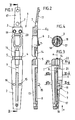
- valve body 1 Shown and described - initially with reference to FIGS. 1-4 - is a valve body 1 which can be used in particular in a dispenser, preferably in a pump dispenser.
- valve body 1 In Fig. 1 the valve body is shown in the opened state, as it is also injected.
- the valve body 1 consists essentially of a dispensing opening part 2 and a closure part 3, which via film joints 4, 5 are interconnected so that the valve body 1 can be injection molded in one piece.
- the closure part 3 forms a check valve 6. This serves to close off a ventilation duct 8.
- a groove-like recess 8 is formed in the dispensing opening part 2, which connects the ventilation opening 7 to the check valve 6.
- the closure tongue 17 is provided with an opening 7.
- the check valve 6 rests on a valve seat 9 which is formed in the dispensing opening part 2.
- the check valve 6, as can be seen in FIG. 2, is injection molded in an excellent manner with regard to its closed state, so that in the closed state (FIG. 3) there is a pretension with which the check valve 6 rests on the valve seat.
- the check valve 6 is molded in such a way that it encloses an angle alpha of, for example, 10 ° with respect to a plane E1 (which coincides here with the parting plane of the two valve parts 2, 3).
- valve body 1 is designed to be elongated, for fitting into a donor neck, as will be described further below with reference to FIGS. 7 and 8.
- the initial geometric shape of the valve body is an elongated round body. This is longitudinally divided in the middle, but connected at one end, via the film hinges 4 and 5 mentioned.
- the ventilation path and the check valve (in the embodiments) are in the folding level or immediately adjacent to it 1 - 4, 7, 8 and 9).
- the donation opening part forms a flow path 12 in cooperation with an inner wall 10 of a donor neck 11.
- a further groove-shaped recess 13 is formed in the dispensing opening part 2, opposite the groove-shaped recess 8.
- the groove-shaped recess 13 is not closed towards the inside of the dispenser in the closed state, but goes into a holder seat 14 for a suction pipe 15 (See, for example, FIGS. 7 and 8 again).
- a semi-cylindrical recess is provided in the dispensing opening part and the closing part 3. These cutouts open in the middle between the film joints 4 and 5.
- the dispensing opening part 2 and the closure part 3 can be latched in the locked state by means of locking pins 15, 16.
- a locking tongue 17 of the locking part 3, in which locking tongue the ventilation opening 7 and a locking knob 18 is formed, is designed to oscillate freely, with an impressed bias in the locked state.
- the closing tongue 17, in the same way as the check valve 6, is injection-molded in cross-section at an angle to the plane E1, likewise with an angle alpha of approximately 8-12 ° in the exemplary embodiment.
- the check valve 6 consists in particular of a flexible valve strip.
- the ventilation path which is interrupted by the check valve 6 continues to the inside of the dispenser beyond the check valve 6. And in the same way through recesses 21, 22 open to the outside, which merge into one another. Again in cooperation with the inner wall 10 of the donor neck 11, a closed flow path also results in this regard.
- the top view according to FIG. 4 shows the mobility of the locking tongue 17 between a closed position and an open position.
- a central axis a of the holder seat 14 runs essentially parallel or in the exemplary embodiment coincides with a parting plane T between the closure part 3 and the dispensing opening part 2.
- the ventilation opening 7 is formed in a cap 23 which, together with a housing 24, forms a dispenser.
- the ventilation opening 7 is covered here by the check valve 6, which extends essentially perpendicular to the parting plane T in the exemplary embodiments in question. Accordingly, the ventilation path in the closure part 3 or in cooperation with the dispensing opening part 2 has ceased to exist.
- valve body 1 according to the exemplary embodiments in FIGS. 5 and 6 has a further locking knob 25, which closes an outlet opening 26 in the dispenser neck 11 from the inside.
- the dispenser neck 11 is formed in the region of the outlet opening 26 and from there down to the inside of the dispenser with such a large inner diameter d that the closure tongue 17 can move freely between a closed position and a dispensed position.
- the head-side end of the dispensing opening part 2 is formed with a cross-sectionally sloping surface 27 for contacting a correspondingly extending section of the inner wall 10 of the donor neck 11.
- the slant 27 causes the locking knobs 25 to be inserted without damage during assembly.
- the swingability of the locking tongue 17 is due to a clear reduction in cross-section between an area in which the locking pins 15, 16 and the locking pin receptacles 19, 20 are formed and the area of the locking tongue 17.
- a rib 17 ' is provided to stiffen the transition. 5a and 6a show an oscillating movement of the locking tongue 17 between a closed position and a dispensing position.
- FIG. 5 shows the suction state after an actuation. Outside air is sucked in through the ventilation opening 7, which enables the dispenser housing 24 designed as a squeeze bottle to be reset after a pump operation.
- the actuation state is indicated in FIG. 6.
- a force is exerted on the dispenser housing 24 in accordance with the arrows b and c, which leads to a squeezing together.
- a pressure increase is achieved in the intermediate space 25.
- This pressure acts on the cartridge 36 and into the interior of the cartridge 36 through the passage opening 27 in the bottom of the cartridge. The pressure propagates to the bottom 29 of the refill 28 and pushes it up.
- the pressure increase in the room 25 also has the result that pressure is applied to the check valve from the inside and the ventilation opening 7 is thus closed. It is ensured that the pressure increase is used to dispense fluid from the dispenser.
- a flow connection is provided between the space 25 and the space 25 ', which is not shown in detail in the drawing.
- the cap 23 forms a dispenser neck 11 with an outlet opening 26 directed at right angles to a vertical axis of the dispenser. Otherwise, essentially the same conditions result as described above for the exemplary embodiments according to FIGS. 5 and 6. Here, however, the air suction is carried out by the closure part 3 itself. After pressure relief, the closure part 3 rests on the through opening 29 in a sealing manner. At the same time, the airway from the outlet opening 26 is opened inwards. The air in the suction state continues to flow through the flow channel 31 between the inner wall 10 and an outer wall of the closure part 3 through the opening 7 and the flow path 32 formed due to the recess 8 to the check valve 6.
- the check valve 6 is raised by the pressure and the air continues to flow through the sections 33 and 35 of the flow path formed in the closure part 3 into the interior of the dispenser .
- the closure flap 23 here forms a cylindrical jacket 34 which is open at the bottom and extends so far that the flow path 12 is closed to the outside. There can be no "short circuit" to the inside of the donor. Rather, the content of the dispenser, for example a liquid, must travel through the dip tube 39. Otherwise, with regard to the dispensers shown only partially in FIGS. 7 and 8, the same function results as with the dispensers described above.
- the dispenser according to FIG. 8 is provided with an upward extension in the flow paths 12 and 31, so that the outlet opening 26 is located approximately in the region of a central axis of the dispenser or in any case in the region a central axis of the cap 23.
- the cartridge 36 consists in detail of a cartridge container (identified by the reference symbol line of the reference symbol 36) and the refill pack 28 or the cartridge bag 28.
- the cartridge bag 28 merges into a closing part 28 'which is relatively rigid.
- the end part 28 ' lies on the edge (28'') on a circumferential edge 36' of the cartridge container and is firmly connected to it, for example glued.
- An upper ventilation opening 37 is formed in the end part 28 '. However, it is also conceivable to provide more than one upper ventilation 37.
- the space between an inner wall of the cartridge container 36 and an outer wall of the cartridge bag 28 can be vented through the upper opening 37 and the lower opening 27.
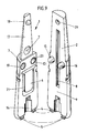
- valve body 1 in the embodiment according to FIGS. 1-4 in perspective, in the separated state.
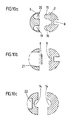
- valve body 1 shows different cross-sectional representations through the valve body 1 according to FIG. 9 or according to FIGS. 1-4.
- the essentially circular structure can be seen in each case.
- the check valve part 6 can freely withdraw into the recess 21.
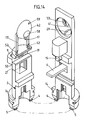
- valve body 1 consisting of the two valve body parts, the closure part 3 and the dispensing opening part 2, can be inserted into an adapter neck 48 of an adapter 46, which in turn is inserted into the container neck 47 (cf. FIGS. 15 and 16). Between the adapter neck 48 and the container neck 47 there is a space into which air slots 49 open to ventilate the container 24.
- the valve body 1 is seated in a cap forming the dispenser neck 11, which can be closed with a slide 57.
- the valve body consists of the two pluggable valve body parts, dispensing opening part 2 and closure part 3, which are integrally connected to one another by means of film hinges 4, 5.
- the closure part 3 has a closure member 17, which has a hemispherical closure head 42, which by means of two tongues 17 ' is formed on the closure part 3 via two spring joints 52.
- the hemispherical closure head 42 is prestressed in a spherical cap 41, which forms the valve seat for the product outlet valve.
- the cap is assigned to the dispensing opening part 2 and has two openings 29, 53.
- the filling material outlet opening 29 adjoins a groove-shaped recess 13, which, in the installed state, forms a flow path for the filling material with the neck inner wall 10.
- the further dispensing opening 53 forms the exit path for the filling material from the dispenser head.
- a pressure is built up inside the dispenser housing 24, it continues through the flow path and acts on the closure head 42 so that it lifts off the dispensing opening 29 or 53, the spring joints 52 taking effect.
- the closure head 42 moves into a chamber 43.
- the change in volume which is forced on the chamber 43 can be compensated for by a compensation opening 59 which is assigned to the portion of the closure head 42 which closes the dispensing opening 53.
- the hemispherical closure head 42 has a trough 58.
- the dispensing opening 53 is made in two parts. The two-part design is brought about by a bolt which separates the dispensing opening 53 parallel to the direction of extension and which closes the compensating opening 49 in the spherical cap 41 when the closure head 42 is in the bearing position.
- the displaced volume is replaced by air.
- This air flows through the flow channel 31 through the dispensing head and passes through a valve seat 9, which is assigned to the closure part 3, into a recess 21, which is connected to the air slots 49 of the adapter 46.
- the air inlet valve formed by the valve seat 9 and a closure tongue 6 assigned to the dispensing opening part 2 protrudes laterally from the essentially circular valve body.
- the recess 21 forms an air duct together with the inner neck wall 10 of the donor neck 11.
- the adapter 46 forms the connecting piece for the filling material flow from the cartridge bag 28 to the valve body 1.
- the valve body is seated in the neck 48 of the adapter 46, the valve body 1 being supported with its mounting seat 14 on an insert fit 62 of the adapter 46.
- the insert fit 62 is formed by an area of the neck 48 with a smaller cross section.
- the cartridge bag 28 is attached to the lower neck area of the adapter 46.
- the neck 48 of the adapter has a smaller outside diameter than the inside diameter of the neck 47 of the container 24.
- the free space between the adapter neck 48 and the container neck 47 forms an air channel for ventilation of the container.
- the adapter In addition to the formation of the air duct, the adapter also has the task of holding the cartridge bag 28 in the container neck 47.
- the adapter has a collar 60, the diameter of which is larger than the inside diameter of the container neck 47 and which rests on the upper edge of the container neck 47.
- the collar is adjoined on the neck side by a collar 63, the outside diameter of which corresponds to the inside diameter of the neck 47, so that the adapter is seated in a form-fitting and centered manner in the neck.
- the air passage between the valve body, here the recess 21, and the container formed by louvers 49 which are associated with the collar 63.
- the adapter 46 is inserted with its collar 60 into a recess in the cap 11, an annular groove 61 being formed on the collar 60 and connecting the air slots 49 with the recess 21. This ensures the ventilation connection between the air inlet valve and the interior of the container.
- the adapter is not centered by a collar 63 in the neck 47 of the container 24, but that the adapter 46 with its collar 60 lies in a form-fitting manner in an annular opening in the cap.
- the cap can also partially extend into the adapter neck 48.
- the valve body is preferably produced in an unfolded position by an injection molding machine.
- the automat is designed so that when the valve body parts are removed from the mold, they are bent around the film hinges 4, 5 and folded into the position shown in FIG. 13.
- the tip of the closure tongue 6 runs on a run-out curve 50 of the closure part and thus comes into a prestressed support on the valve seat 9.
- the connection between the dispensing opening part 2 and the closure part 3 is established by the locking pin 15, which is locked with a pin recess 19.
- the locking pin 15 is mushroom-shaped in cross-section, the mushroom-shaped head having a slightly larger diameter than the pin recess 19.
- the separating surface T formed by the two valve body parts 2, 3 also serves in this embodiment for Separation of product channels and air channels, the product channels being assigned to the dispensing opening part 2 and the air channels being assigned to the closure part 3.
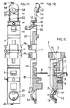
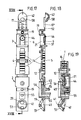
- FIGS. 17-22 A fourth embodiment of the valve body is shown in FIGS. 17-22. As described in relation to the third embodiment, this embodiment also has a hemispherical closure head 42 which lies in a carrot 41 and forms the filling material outlet valve. The filling material exits through the flow path 12 into a dividing flow path 45 which is formed together by the inner wall of the neck and two parallel grooves, both paths reuniting in front of the cap 41. These two parallel product paths 45 enclose an air channel 56, which adjoins the seat of the air inlet valve and which opens into a transverse channel 55, which in turn opens into an air flow channel assigned to the dispensing cap.
- the air inlet valve is formed by a closure member 6, a closure flap 44 being formed on a closure tongue and resting on a valve seat 9.
- the closure member 6 is connected to a spring joint 51 on the closure part 3.
- Both the filling material outlet valve and the air inlet valve are formed in the parting plane T.
- the air inlet duct crosses twice the parting plane, once by forming the valve seat and again by a transverse duct 55 which is connected to the flow duct 31 by the groove 56.
- the transverse channel 55 passes through a free space formed by the closure member tongues 17 '.
- grooves arranged on the valve body surface form in cooperation with the inner wall 10 of the dispensing neck 11 grooves in which air or product is transported.
Landscapes
- Engineering & Computer Science (AREA)
- Mechanical Engineering (AREA)
- General Engineering & Computer Science (AREA)
- Containers And Packaging Bodies Having A Special Means To Remove Contents (AREA)
Abstract
Die Erfindung betrifft einen Ventilkörper (1) für einen Spender, insbesondere einen Spender mit zusammendrückbarem und elastisch rückstellfähigem Behältnis und mit selbstschließenden Füllgutaustritts- und Lufteintrittsventil. Zur Erzielung einer möglichst einfachen Herstellbarkeit und einer gebrauchsvorteilhafteren Ausgestaltung schlägt die Erfindung vor zwei miteinander verbindbare, insbesondere rastverbindbare, eine sich in Ventilkörperlängsrichtung erstreckende Trennebene (T) ausbildende Ventilkörperteile (2, 3), nämlich ein Verschlußteil (3) und ein Spendeöffnungsteil (2) vorzusehen, wobei das Füllgutaustrittsventil von einem Verschlußglied (17), das im Bereich der Trennebene (T) dem Verschlußteil (3) in Ventilkörperlängsrichtung federnd schwingbar angeformt ist zur verschließenden Auflage auf einem dem Spendeöffnungsteil (2) zugeordneten Ventilsitz (29, 41) gebildet ist.
Description
Die Erfindung betrifft einen Ventilkörper für eine Spender, insbesondere einen Spender mit zusammendrückbarem und elastisch rückstellfähigem Behältnis und mit selbstschließenden Füllgutaustritts- und Lufteintrittsventil. Darüber hinaus betrifft die Erfindung eine Kartusche und einen Spender mit einer Kartusche und einem Ventilkörper.The invention relates to a valve body for a dispenser, in particular a dispenser with a compressible and elastically resilient container and with a self-closing filling material outlet and air inlet valve. Furthermore, the invention relates to a cartridge and a dispenser with a cartridge and a valve body.
Ein derartiger Spender ist bekannt aus der PCT/CH85/00109, bei dem mittels eines im Behältnis aufgebauten Druckes Füllgut durch ein Saugrohr in einen Ventilkörper gedrückt wird und durch ein Füllgutaustrittsventil aus dem Ventilkörper heraustritt. Der Druck wird bei diesem Spender durch ein Zusammendrücken des elastisch rückstellfähigen Behältnisses erzeugt. Nach dem Zusammendrücken wird das durch das Austrittsventil herausgetretene Füllgutvolumen durch Luft ersetzt, die durch ein Lufteintrittsventil in das Behältnis strömen kann. Bei dieser Lösung ist eine Vielzahl von Bauteilen gegeben und die Montage entsprechend aufwendig.Such a dispenser is known from PCT / CH85 / 00109, in which filling material is pressed through a suction pipe into a valve body by means of a pressure built up in the container and exits the valve body through a filling material outlet valve. With this dispenser, the pressure is generated by compressing the elastically resilient container. After the compression, the volume of product which has emerged through the outlet valve is replaced by air which can flow into the container through an air inlet valve. This solution provides a large number of components and the assembly is correspondingly complex.
Ausgehend von diesem Stand der Technik stellt sich der Erfindung die Aufgabe, einen gattungsgemäßen Ventilkörper anzugeben, der bei einfacher Herstellbarkeit gebrauchsvorteilhaft ausgebildet ist.Proceeding from this prior art, the object of the invention is to provide a generic valve body which is designed to be advantageous in use and easy to manufacture.
Diese Aufgabe ist bei dem im Anspruch 1 angegebenen Ventilkörper gelöst durch zwei miteinander verbindbare, insbesondere verrastbare, eine sich in Ventilkörperlängsrichtung erstreckende Trennebene ausbildende Ventilkörperteile, nämlich ein Verschlußteil und ein Spendeöffnungsteil, wobei das Füllgutaustrittsventil von einem Verschlußglied gebildet ist, das im Bereich der Trennebene dem Verschlußteil in Ventilkörperlängsrichtung federnd schwingbar angeformt ist zur verschließenden Auflage auf einem dem Spendeöffnungsteil zugeordneten Ventilsitz.This object is achieved in the valve body specified in
Zufolge derartiger Ausgestaltung ist ein insbesondere spritztechnisch einfach herstellbarer Ventilkörper gegeben. Er besteht lediglich aus zwei zusammensteckbaren Ventilkörperteilen, die zusammen das Füllgutaustrittsventil ausbilden. Dabei ist es vorteilhaft, die Ventilkörperteile, Verschlußteil und Spendeöffnungsteil, einstückig miteinander auszubilden. Die beiden Ventilkörperteile können dann als einzelnes Spritzgußteil hergestellt werden, das dann nur noch zusammengeklappt werden braucht, so daß die Trennebene ausgebildet wird. Vorteilhaft ist weiterhin einem der beiden Ventilkörperteile ein weiteres Verschlußglied anzuformen, das in verschließender Auflage auf einem Ventilsitz eines Lufteintrittsventils liegen kann. Es ist vorgesehen, daß der Ventilsitz des Lufteintrittsventils von dem anderen Ventilkörperteil ausgebildet wird. Auch sind Ausgestaltungen der Erfindung vorgesehen, bei denen der Ventilsitz des Lufteintrittsventils nicht von einem der Ventilkörperteile gebildet wird, sondern von einer Kappe oder dergleichen, in der das Ventilkörperteil Aufnahme findet. Bei einem mit einem erfindungsgemäßen Verschlußteil ausgestatteter Spender wird der Überdruck beispielsweise gleichsam einer Quetschflasche durch Zusammendrücken des Spenderbehälters erzeugt. Bei diesem Pumpvorgang ist durch das selbstverschließende, als Rückschlagventil ausgebildete Lufteintrittsventil ein abgeschlossener Luftraum im Spender ausgebildet, so daß der erforderliche Überdruck beim Pumpvorgang aufgebaut werden kann. Die Anordnung sowohl des Füllgutaustrittsventils als auch des Lufteintrittsventils in einem aus zwei Ventilkörperteilen bestehenden Ventilkörper ist besonders vorteilhaft. Im Ventilkörper sind dann Kanäle ausgebildet, in denen die Luft durch das Lufteintrittsventil bei sich zurückstellendem Behälter einströmen kann. Der einteilig, beispielsweise aus Polypropylen gespritzte Ventilkörper ist weiter bevorzugt langgestreckt ausgebildet, zur Einpassung in einen Spenderhals. Dabei weisen die beiden Ventilkörperteile, Verschlußteil und Spendeöffnungsteil jeweils einen im wesentlichen halbkreisförmigen Querschnitt auf, so daß der Ventilkörper einen kreisförmigen Querschnitt ausbildet. Die Öffnungsebene des Verschlußgliedes des Füllgutaustrittsventils, die mit der Trennebene zwischen dem Spendeöffnungsteil und dem Verschlußteil zusammenfällt, verläuft in etwa parallel zu einer Mittelachse des Spenders. Der Ventilkörper ist geeignet ausgestaltet zur Einpassung in einen Spenderhals, wobei das Spendeöffnungsteil in Zusammenwirkung mit einer Innenwand des Spenderhalses Strömungskanäle ausbildet. Hierzu sind auf der Ventilkörperaußenwand nutenförmige Aussparungen vorgesehen. Diese Strömungskanäle können zur Leitung von Füllgut zur Spendeöffnung dienen aber auch zum Lufteintritt. Sind sowohl Luftkanäle als auch Füllgutkanäle vorgesehen, so sind diese voneinander getrennt. Das Verschlußglied des Füllgutaustrittsventils und/oder des Lufteintrittsventils sind vorzugsweise als federnde Zungen ausgebildet. Insbesondere die federnde Zunge des Lufteintrittsventils kann sich dabei auch quer zur Ventilkörperlängsrichtung erstrecken. Auch ist vorgesehen, das Verschlußglied mit einem Noppen zu versehen, zum Verschluß einer Ventilöffnung. Eine weitere Ausgestaltung der Erfindung sieht ein Verschlußglied vor, bei dem zwei parallel verlaufende am Verschlußteil angeformte Zungen einen im wesentlichen halbkugelförmigen Verschlußkopf tragen, der in einen formangepaßten vom Spendeöffnungsteil ausgebildeten kalottenförmigen Ventilsitz eintreten kann. Auch ist vorgesehen, das Verschlußglied mit einem zweiten Noppen auszugestalten, zum Verschließen der Spenderöffnung des Spendeöffnungsteils. Diese Spenderöffnug kann insbesondere einem Spenderhals zugeordnet sein, in den der Ventilkörper eingepaßt ist. Das Spendeöffnungsteil und das Verschlußteil sind, auch bei einteiliger Ausführung, im Einbauzustand bevorzugt klipsverbunden. Ein als Verschlußzunge ausgestaltetes Verschlußglied ist mit einer eingeprägten Vorspannung in den Verschlußzustand angespritzt. Hierdurch ist in zusammengestecktem Zustand eine Ventilabdichtung gewährleistet. Das als Rückschlagventil ausgestaltete Lufteintrittsventil besteht vorzugweise aus einem flexiblen, streifenförmigen Abschnitt, und bei Ausbildung der Lüftungsöffnung in dem Verschlußteil ist an dem Spendeöffnungsteil ein Ventilsitz angeformt. An diesem Ventilsitz ist das flexible Streifenteil im Verschlußzustand unter Vorspannung in Anlage. Bevorzugt ist vorgesehen, daß das Spendeöffnungsteil und/oder das Verschlußteil einendig einen Halterungssitz für ein Saugrohr ausbilden und daß der Halterungssitz an den Strömungsweg für das Füllgut, bei dem es sich vorzugsweise um ein Fluid handelt, angeschlossen ist. Ein solches Saugrohr ist insbesondere von Bedeutung, wenn der Spender mit Flüssigkeit gefüllt ist. Der Ventilkörper bildet also unmittelbar eine Halterung für das Saugrohr aus. Die Mittelachse des Halterungssitzes verläuft bevorzugt parallel zu der Trennebene zwischen dem Verschlußteil und dem Spendeöffnungsteil. Der Halterungssitz ist entsprechend einendig an den zusammengeklappten Ventilkörper ausgeformt. Bei einer Aufklappung des Ventilkörpers, wie er im Spritzzustand vorliegt, befindet sich die Halterungsöffnung bzw. die Ausformungen, die anschließend die Halterungsöffnung bilden, entsprechend mittig zwischen den beiden Teilen, zwischen dem Spendeöffnungsteil und dem Verschlußteil. Weiter bevorzugt ist der Ventilkörper derart ausgestaltet, daß eine Querschnittsfläche in zusammengeklapptem Zustand des Ventilkörpers im wesentlichen kreisförmig ist. Hierbei auch zunächst unabhängig von der Lage der Querschnittsfläche. Die beiden Ventilkörperteile sind vorzugsweise durch Filmscharniere verbunden. Gemäß einer bevorzugten Ausgestaltung der Erfindung ist das Verschlußglied von Füllgutaustrittsventil und/oder Lufteintrittsventil mit einem als Materialverdünnung ausgestalteten Federgelenk mit dem Ventilkörperteil verbunden. Durch diese Materialverdünnung kann trotz starrer Ausführung des Verschlußgliedes eine geringe, ausreichende Rückstellkraft erzielt werden. Bei einer Ausgestaltung des Ventilkörpers, bei der das Füllgutaustrittsventil einen halbkugelförmigen Ventilkopf aufweist, der in einem kalottenförmig gestalteten Ventilsitz einliegt, weist der Ventilsitz zusätzlich zu einer ersten Füllgutaustrittsöffnung noch eine zweite Spendeöffnung auf, die beide durch den halbkugelförmigen Verschlußkopf verschließbar sind. Beim Spenden fließt das Füllgut nacheinander durch beide Öffnungen. Eine weitere spezielle Ausgestaltung der Erfindung sieht parallel verlaufende nutenförmige Aussparungen in der Ventilkörperaußenwand vor, zur Ausbildung je eines Kanales für den Füllgutfluß und den Luftfluß. Auch ist vorgesehen, den Kanal für den Füllgutfluß doppelt auszugestalten, wobei er beidseitig vom Luftflußkanal angeordnet sein kann. Weiter ist vorgesehen, daß die vorzugsweise durch eine Rastzapfenverbindung zusammengefügten Ventilkörperteile zumindestens einen Querkanal insbesondere zur Luftführung aufweisen. Um eine dichtende Verbindung mit dem Spenderbehälter zu erzielen, weist der Ventilkörper einen Halterungssitz auf, mit dem er im Hals des Spenderbehältnisses formschlüssig eingesteckt ist. Eine spezielle Ausgestaltung sieht hierbei vor, daß der Ventilkörper mit einem Halterungssitz in einen Hals eines Adapters formschlüssig einsitzt, welcher wiederum in einem Hals des Behältnisses einsitzt derart, daß zwischen Adapterhals und Behälterhals ein Freiraum besteht, in welchem Luftschlitze münden, die das Belüften der Flasche ermöglichen. Bei einer speziellen Ausgestaltung des Ventilkörpers, bei dem die beiden Ventilkörperteile mittels Filmscharnier am Halterungssitz verbunden sind, weist ein Ventilkörperteil ein als Zunge ausgestaltetes Verschlußglied des Lufteintrittsventiles auf, das sich quer zur Ventilkörperlängsrichtung erstreckt und die Trennebene schneidet. Das andere Ventilkörperteil weist eine der Spitze der Zunge zugeordnete Auflaufkurve auf, die derart ausgebildet ist, daß beim Zusammenklappen der beiden Ventilkörperteile die Zungenspitze auf die Fläche der Auflaufkerbe trifft, wobei sie in eine vorgespannte Lage geschwenkt wird.As a result of such a configuration, there is a valve body that is particularly easy to produce by injection molding. It only consists of two pluggable valve body parts, which together form the product outlet valve. It is advantageous to form the valve body parts, closure part and dispensing opening part in one piece with one another. The two valve body parts can then be produced as a single injection molded part, which then only needs to be folded together, so that the parting plane is formed. It is also advantageous to mold one of the two valve body parts to a further closure member, which can lie in a closing position on a valve seat of an air inlet valve. It is envisaged that the valve seat of the air inlet valve is formed by the other valve body part. Embodiments of the invention are also provided in which the valve seat of the air inlet valve is not formed by one of the valve body parts, but by a cap or the like in which the valve body part is accommodated. In the case of a dispenser equipped with a closure part according to the invention, the overpressure is generated, for example, like a squeeze bottle, by compressing the dispenser container. In this pumping process, a self-closing air inlet valve designed as a check valve forms a closed air space in the dispenser, so that the required excess pressure can be built up during the pumping process. The arrangement of both the product outlet valve and the air inlet valve in a valve body consisting of two valve body parts is particularly advantageous. In the valve body channels are then formed in which the air can flow in through the air inlet valve when the container is returning. The one-piece, for example injection-molded from polypropylene, valve body is further preferably elongated, for fitting into a donor neck. The two valve body parts, the closure part and the dispensing opening part each have an essentially semicircular cross section, so that the valve body forms a circular cross section. The opening plane of the closure member of the product outlet valve, which coincides with the parting plane between the dispensing opening part and the closure part, runs approximately parallel to a central axis of the dispenser. The valve body is suitably designed for fitting into a donor neck, the donor opening part in cooperation with an inner wall of the donor neck forming flow channels. For this purpose, groove-shaped recesses are provided on the outer wall of the valve body. These flow channels can be used to direct the filling material to the dispensing opening, but also to allow air to enter. If both air channels and product channels are provided, these are separated from one another. The closure member of the product outlet valve and / or the air inlet valve are preferably designed as resilient tongues. In particular, the resilient tongue of the air inlet valve can also extend transversely to the longitudinal direction of the valve body. It is also provided to provide the closure member with a knob for closing a valve opening. A further embodiment of the invention provides a closure member in which two parallel tongues formed on the closure part carry an essentially hemispherical closure head which can enter into a shape-fitting dome-shaped valve seat formed by the dispensing opening part. It is also provided the closure member to design with a second knob to close the dispenser opening of the dispensing opening part. This dispenser opening can in particular be assigned to a dispenser neck into which the valve body is fitted. The dispensing opening part and the closure part, even in the case of a one-piece design, are preferably clip-connected in the installed state. A closure member designed as a closure tongue is injection molded with an impressed preload into the closure state. This ensures a valve seal when plugged together. The air inlet valve designed as a check valve preferably consists of a flexible, strip-shaped section, and when the ventilation opening is formed in the closure part, a valve seat is formed on the dispensing opening part. The flexible strip part is in contact with this valve seat in the closed state under pretension. It is preferably provided that the dispensing opening part and / or the closure part form a holder seat for a suction pipe at one end and that the holder seat is connected to the flow path for the filling material, which is preferably a fluid. Such a suction tube is particularly important when the dispenser is filled with liquid. The valve body thus directly forms a holder for the intake manifold. The central axis of the holder seat preferably runs parallel to the parting plane between the closure part and the dispensing opening part. The bracket seat is formed at one end on the folded valve body. When the valve body is opened, as it is in the sprayed state, the holder opening or the formations which subsequently form the holder opening are correspondingly centered between the two parts, between the dispensing opening part and the closure part. The valve body is further preferably designed such that a cross-sectional area in the folded state of the valve body is substantially circular. Here, regardless of the position of the cross-sectional area. The two valve body parts are preferably connected by film hinges. According to a preferred embodiment of the invention, the closure member of the product outlet valve and / or air inlet valve is connected to the valve body part with a spring joint designed as a material thinner. Through this thinning of material, a small, sufficient restoring force can be achieved despite the rigid design of the closure member. In one embodiment of the valve body, in which the product outlet valve has a hemispherical valve head which lies in a dome-shaped valve seat, the valve seat has, in addition to a first product outlet opening, a second dispensing opening, both of which can be closed by the hemispherical closure head. When dispensing, the contents flow through both openings one after the other. Another special embodiment of the invention provides parallel groove-shaped recesses in the outer wall of the valve body to form a channel for the flow of the filling material and the air flow. It is also provided that the channel for the filling material flow is designed twice, it being possible for it to be arranged on both sides of the air flow channel. It is further provided that the valve body parts, which are preferably joined together by a locking pin connection, have at least one transverse channel, in particular for air guidance. In order to achieve a sealing connection with the dispenser container, the valve body has a mounting seat with which it is inserted in a form-fitting manner in the neck of the dispenser container. A special embodiment provides for the valve body to be seated in a form-fitting manner in a neck of an adapter, which, in turn, sits in a neck of the container in such a way that there is a free space between the adapter neck and the container neck, in which air slots open, which enable the bottle to be vented. In a special embodiment of the valve body, in which the two valve body parts are connected to the mounting seat by means of a film hinge, a valve body part has a closure element of the air inlet valve, which is designed as a tongue and extends transversely to the longitudinal direction of the valve body and intersects the parting plane. The other valve body part has a run-up curve assigned to the tip of the tongue, which is designed such that when the two valve body parts are folded together, the tip of the tongue hits the surface of the run-up notch, wherein it is pivoted into a prestressed position.
Der zuvor beschriebene Ventilkörper ist insbesondere gedacht für eine Verwendung in einem Spender mit einer Nachfüllkartusche. Hierbei ist bevorzugt die Kartusche als kollabierfähiger Kartuschenbeutel ausgebildet. Der Kartuschenbeutel wird durch Ausdrücken geleert. In diesem Zusammenhang sieht die Erfindung auch vor, daß der Kartuschenbeutel in einem Kartuschenbehälter aufgenommen ist und daß in einem Deckenbereich und in einem Bodenbereich der Einheit Kartuschenbehälter/Kartuschenbeutel eine (Lüftungs-) Durchtrittsöffnung ausgebildet ist. Die Einheit Kartuschenbehälter/Kartuschenbeutel besitzt also zwei Lüftungsdurchtrittsöffnungen. Dies ermöglicht es, den Kartuschenbehälter umlaufend dichtend in dem Spender aufzunehmen, wobei oberhalb und unterhalb des Dichtbereiches eine Entlüftungsöffnung gegeben ist. Durch die obere Durchtrittsöffnung kann sodann Luft beispielsweise von außerhalb des Spenders nachgesaugt werden. Hierbei ist weiter bevorzugt, daß die obere Lüftungsöffnung in einem oberen, im wesentlichen starren Abschlußteil des Kartuschenbeutels ausgebildet ist. Auf diesen Kartuschenbeutel kann umfangsrandseitig eine Dichtkante des Spenderoberteiles umlaufend einwirken (im zusammengebauten Zustand).The valve body described above is intended in particular for use in a dispenser with a refill cartridge. Here, the cartridge is preferably designed as a collapsible cartridge bag. The cartridge bag is emptied by squeezing it out. In this context, the invention also provides that the cartridge bag is accommodated in a cartridge container and that a (ventilation) passage opening is formed in a ceiling area and in a bottom area of the cartridge container / cartridge bag unit. The cartridge container / cartridge bag unit thus has two ventilation openings. This makes it possible to receive the cartridge container in a circumferentially sealing manner in the dispenser, with a ventilation opening being provided above and below the sealing area. Air can then be sucked in from the outside of the dispenser, for example, through the upper passage opening. It is further preferred that the upper ventilation opening in an upper, substantially rigid end part of the cartridge bag is formed. A sealing edge of the upper part of the dispenser can have a circumferential effect on the circumferential edge of this cartridge bag (in the assembled state).
Nachstehend ist die Erfindung desweiteren im einzelnen mit Bezug zu der beigefügten Zeichnung erläutert, die jedoch lediglich Ausführungsbeispiele darstellt. Hierbei zeigt:
- Fig. 1
- eine Draufsicht auf einen Ventilkörper, aufgeklappt;
- Fig. 2
- einen Schnitt durch den Gegenstand gemäß Fig. 1, geschnitten entlang der Linie II-II;
- Fig. 3
- eine Schnittdarstellung gemäß Fig. 2, im geschlossenen Zustand;
- Fig. 4
- eine Draufsicht auf den Gegenstand gemäß Fig. 3, gesehen in Richtung des Pfeiles a;
- Fig. 5
- einen Längsschnitt durch einen Spender mit eingebautem Ventilkörper, im Zustand der Luftnachsaugung;
- Fig. 5a
- einen Querschnitt durch den Gegenstand gemäß Fig. 5 entlang der Linie Va-Va;
- Fig. 6
- einen Längsschnitt entsprechend Fig. 5 , im Ausgabezustand;
- Fig. 6a
- einen Querschnitt durch den Gegenstand gemäß Fig. 6 entlang der Linie VIa-VIa;
- Fig. 7
- einen Längsschnitt durch einen Spenderkopf mit einem Ventilkörper mit in dem Verschlußteil ausgebildeter Lüftungsöffnung;
- Fig. 8
- einen Gegenstand gemäß Fig. 7 mit abgewandeltem Spenderkopf;
- Fig. 9
- eine perspektivische Darstellung des Ventilkörpers, im aufgetrennten Zustand;
- Fig. 10a
- einen Querschnitt durch den Ventilkörper gemäß Fig. 9, geschnitten im Bereich der Verschlußzapfen;
- Fig. 10b
- ein Schnitt durch den Gegenstand gemäß Fig. 9, geschnitten im Bereich der Verschlußzunge,
- Fig. 10c
- ein Schnitt durch den Ventilkörper gemäß Fig. 9, geschnitten im Bereich des Halterungssitzes für das Saugrohr,
- Fig. 11
- eine Draufsicht auf einen aufgeklappten Ventilkörper einer dritten Ausführungsform,
- Fig. 12
- einen Schnitt durch den Gegenstand gemäß Fig. 11 entlang der Linie XII-XII,
- Fig. 13
- eine Schnittdarstellung des Gegenstandes gemäß Fig. 11 in verbundenem Zustand,
- Fig. 14
- eine perspektivische Darstellung der beiden Ventilkörperteile gemäß der dritten Ausführungsform,
- Fig. 15
- ein in einen Spender eingesetzten Ventilkörper der dritten Ausführungsform in Spendestellung,
- Fig. 16
- eine Darstellung gemäß Fig. 15 jedoch in Luftansaugstellung,
- Fig. 17
- eine Darstellung gemäß Fig. 11 einer vierten Ausführungsform,
- Fig. 18
- eine Darstellung gemäß Fig. 12 einer vierten Ausführungsform,
- Fig. 19
- eine Darstellung gemäß Fig. 13 einer vierten Ausführungsform,
- Fig. 20
- eine perspektivische Darstellung der beiden Ventilkörperteile gemäß der vierten Ausführungsform,
- Fig. 21
- ein in einen Spenderkopf eingesteckten Ventilkörper der vierten Ausführungsform und
- Fig. 22
- eine Rückansicht des Spendeöffnungsteils der vierten Ausführungsform.
- Fig. 1
- a plan view of a valve body, opened;
- Fig. 2
- a section through the object of Figure 1, cut along the line II-II.
- Fig. 3
- a sectional view of Figure 2, in the closed state.
- Fig. 4
- a plan view of the object of Figure 3, seen in the direction of arrow a.
- Fig. 5
- a longitudinal section through a dispenser with built-in valve body, in the state of air suction;
- Fig. 5a
- a cross section through the object of Figure 5 along the line Va-Va.
- Fig. 6
- a longitudinal section corresponding to Figure 5, in the output state.
- Fig. 6a
- a cross section through the object of Figure 6 along the line VIa-VIa.
- Fig. 7
- a longitudinal section through a dispenser head with a valve body with a ventilation opening formed in the closure part;
- Fig. 8
- an object according to FIG 7 with a modified dispenser head.
- Fig. 9
- a perspective view of the valve body, in the separated state;
- Fig. 10a
- a cross section through the valve body according to FIG 9, cut in the region of the locking pin.
- Fig. 10b
- 9 shows a section through the object according to FIG. 9, cut in the region of the closure tongue,
- Fig. 10c
- 9 shows a section through the valve body according to FIG. 9, cut in the region of the mounting seat for the intake manifold,
- Fig. 11
- a plan view of an opened valve body of a third embodiment,
- Fig. 12
- 11 shows a section through the object according to FIG. 11 along the line XII-XII,
- Fig. 13
- 11 shows a sectional illustration of the object according to FIG. 11 in the connected state,
- Fig. 14
- 2 shows a perspective illustration of the two valve body parts according to the third embodiment,
- Fig. 15
- a valve body of the third embodiment inserted into a dispenser in the dispensing position,
- Fig. 16
- 15 but in the air intake position,
- Fig. 17
- 11 shows a representation according to FIG. 11 of a fourth embodiment,
- Fig. 18
- 12 shows a representation according to FIG. 12 of a fourth embodiment,
- Fig. 19
- 13 shows a representation according to FIG. 13 of a fourth embodiment,
- Fig. 20
- 2 shows a perspective illustration of the two valve body parts according to the fourth embodiment,
- Fig. 21
- a valve body of the fourth embodiment inserted into a dispenser head and
- Fig. 22
- a rear view of the dispensing opening part of the fourth embodiment.
Dargestellt und beschrieben ist - zunächst mit Bezug zu den Fig. 1 - 4 - ein Ventilkörper 1, der insbesondere bei einem Spender, vorzugsweise bei einem Pumpspender, Verwendung finden kann.Shown and described - initially with reference to FIGS. 1-4 - is a
In Fig. 1 ist der Ventilkörper im aufgeklappten Zustand dargestellt, wie er auch gespritzt wird. Der Ventilkörper 1 besteht im wesentlichen aus einem Spendeöffnungsteil 2 und einem Verschlußteil 3, die über Filmgelenke 4, 5 miteinander verbunden sind, so daß der Ventilkörper 1 einteilig gespritzt werden kann.In Fig. 1 the valve body is shown in the opened state, as it is also injected. The
Wie insbesondere Fig. 2 zu entnehmen ist, bildet das Verschlußteil 3 ein Rückschlagventil 6 aus. Dieses dient zum Abschluß eines Lüftungskanals 8. Wie einer Zusammenschau der Figuren 1 - 3 zu entnehmen ist, ist in dem Spendeöffnungsteil 2 eine nutartige Ausnehmung 8 ausgeformt, welche die Lüftungsöffnung 7 mit dem Rückschlagventil 6 verbindet. Damit die Luft und eventuelle Füllgutreste schneller in den Kanal 8 gelangen, ist die Verschlußzunge 17 mit einer Öffnung 7 versehen.Das Rückschlagventil 6 liegt auf einem Ventilsitz 9 auf, der in dem Spendeöffnungsteil 2 ausgebildet ist.As can be seen in particular in FIG. 2, the
Weiter ist das Rückschlagventil 6, wie Fig. 2 zu entnehmen ist, vorragend bezüglich seines Verschlußzustandes angespritzt, so daß sich im Verschlußzustand (Fig. 3) eine Vorspannung ergibt, mit welcher das Rückschlagventil 6 auf dem Ventilsitz aufliegt. Bei dem Ausführungsbeispiel ist das Rückschlagventil 6 derart angespritzt, daß es bezüglich einer Ebene E1 (die hier mit der Trennebene der beiden Ventilteile 2, 3 zusammenfällt) einen Winkel Alpha von beispielsweise 10° mit dieser einschließt.Furthermore, the
Weiter ist, wie ersichtlich, der Ventilkörper 1 langgestreckt ausgebildet, zur Einpassung in einen Spenderhals, wie dies weiter unten noch in bezug auf die Fig. 7 und 8 beschrieben ist. Die geometrische Ausgangsform des Ventilkörpers ist ein langgestreckter Rundkörper. Dieser ist mittig längsgeteilt, jedoch einendig, über die erwähnten Filmscharniere 4 und 5, verbunden. In der Klappebene bzw. unmittelbar angrenzend an diese) ist der Lüftungsweg und das Rückschlagventil (bei den Ausführungsformen nach den Fig. 1 - 4, 7, 8 und 9) ausgebildet. Das Spendeöffnungsteil bildet hierbei in Zusammenwirkung mit einer Innenwand 10 eines Spenderhalses 11 einen Strömungsweg 12 aus. Hierzu ist in dem Spendeöffnungsteil 2 eine weitere nutförmige Aussparung 13 ausgebildet, gegenüberliegend zu der nutförmigen Aussparung 8. Die nutförmige Aussparung 13 ist im Gegensatz zu der nutförmigen Aussparung 8 im Verschlußzustand zum Spenderinneren hin nicht verschlossen, sondern geht in einen Halterungssitz 14 für ein Saugrohr 15 (vergl. hierzu beispielsweise wieder Fig. 7 und 8) über. Bei dem Ausführungsbeispiel ist in dem Spendeöffnungsteil und dem Verschlußteil 3 jeweils eine halb zylinderschalenförmige Aussparung vorgesehen. Diese Aussparungen münden mittig zwischen den Filmgelenken 4 und 5.Furthermore, as can be seen, the
Desweiteren ist das Spendeöffnungsteil 2 und das Verschlußteil 3 mittels Verschlußzapfen 15, 16 im Verschlußzustand rastverbindbar. Eine Verschlußzunge 17 des Verschlußteils 3, in welcher Verschlußzunge die Lüftungsöffnung 7 und ein Verschlußnoppen 18 ausgebildet ist, ist frei schwingbar ausgebildet, mit einer eingeprägten Vorspannung in den Verschlußzustand. Wie insbesondere Fig. 2 zu entnehmen ist, ist hierzu die Verschlußzunge 17, in gleicher Weise wie das Rückschlagventil 6, im Querschnitt winklig zu der Ebene E1 gespritzt, gleichfalls mit einem Winkel Alpha von ca. 8 - 12° beim Ausführungsbeispiel.Furthermore, the
Das Rückschlagventil 6 besteht im einzelnen aus einem flexiblen Ventilstreifen.The
Zur Aufnahme der erwähnten Rastzapfen 15 und 16, die beidseitig zu der Aussparung 8, etwa mittig zu dieser, angeordnet sind, sind in dem Verschlußteil 3 entsprechende Zapfenaufnahmen 19, 20 vorgesehen, in welche die Verschlußzapfen 15, 16 im Verschlußzustand eingefahren sind.For receiving the mentioned locking pins 15 and 16, which are arranged on both sides of the
Entsprechend dem Strömungsweg 12 für aus dem Spender auszubringendes Medium setzt sich auch der Lüftungsweg, der durch das Rückschlagventil 6 unterbrochen ist, zum Spenderinneren hin jenseits des Rückschlagventiles 6 fort. Und zwar in gleicher Weise durch nach außen hin offene Aussparungen 21, 22, die ineinander übergehen. Wiederum in Zusammenwirkung mit der Innenwand 10 des Spenderhalses 11 ergibt sich auch diesbezüglich ein geschlossener Strömungsweg.Corresponding to the
Der Draufsicht gemäß Fig. 4 ist die Beweglichkeit der Verschlußzunge 17 zwischen einer Verschlußstellung und einer Öffnungsstellung zu entnehmen.The top view according to FIG. 4 shows the mobility of the locking
Eine Mittelachse a des Halterungssitzes 14 verläuft im wesentlichen parallel bzw. fällt beim Ausführungsbeispiel zusammen mit einer Trennebene T zwischen dem Verschlußteil 3 und dem Spendeöffnungsteil 2.A central axis a of the
Bei den Ausführungsbeispielen gemäß den Fig. 5 und 6 ist die Lüftungsöffnung 7 in einer Kappe 23 ausgebildet, die zusammen mit einem Gehäuse 24 einen Spender ausformt. Die Lüftungsöffnung 7 ist hier durch das Rückschlagventil 6 abgedeckt, das sich im wesentlichen senkrecht zu der Trennebene T bei den in Rede stehenden Ausführungsbeispielen erstreckt. Entsprechend ist der Lüftungsweg in dem Verschlußteil 3 bzw. in Zusammenwirkung mit dem Spendeöffnungsteil 2 in Fortfall gekommen.In the exemplary embodiments according to FIGS. 5 and 6, the
Weiter weist der Ventilkörper 1 gemäß den Ausführungsbeispielen der Fig. 5 und 6 noch einen weiteren Verschlußnoppen 25 auf, der eine Austrittsöffnung 26 in dem Spenderhals 11 von innen verschließt. Der Spenderhals 11 ist im Bereich der Austrittsöffnung 26 und von dort abwärts zum Spenderinneren hin mit einem solch großen inneren Durchmesser d ausgebildet, daß die Verschlußzunge 17 ungehindert zwischen einer Verschlußstellung und einer Spendestellung schwingend sich bewegen kann.Furthermore, the
Das kopfseitige Ende des Spendeöffnungsteiles 2 ist mit einer im Querschnitt schräg verlaufenden Fläche 27 ausgebildet, zur Anlage an einem entsprechend verlaufenden Abschnitt der Innenwand 10 des Spenderhalses 11. Die Schräge 27 bewirkt ein beschädigungsfreies Einführen des Verschlußnoppen 25 bei der Montage.The head-side end of the
Die Schwingbarkeit der Verschlußzunge 17 ist durch eine deutliche Querschnittsverminderung zwischen einem Bereich, in dem die Rastzapfen 15, 16 und die Rastzapfenaufnahme 19, 20 ausgebildet sind und dem Bereich der Verschlußzunge 17. Zur Versteifung des Überganges ist eine Rippe 17' vorgesehen. Den Fig. 5a und 6a ist eine Schwingbewegung der Verschlußzunge 17 zwischen einer Verschlußstellung und einer Spendestellung zu entnehmen.The swingability of the locking
Die Funktion der in den Fig. 5 und 6 dargestellten Spender und des darin angeordneten Ventilkörpers 1 ist wie folgt: In Fig. 5 ist der Ansaugzustand nach einer Ausdrückbetätigung dargestellt. Durch die Lüftungsöffnung 7 wird Außenluft angesaugt, die eine Rückstellung des als Quetschflasche ausgebildeten Spendergehäuse 24 nach einer Pumpbetätigung ermöglicht. In Fig. 6 ist der Betätigungszustand angedeutet. Auf das Spendergehäuse 24 wird entsprechend den Pfeilen b und c eine Kraft ausgeübt, die zu einem Zusammenquetschen führt. Hierdurch wird in dem Zwischenraum 25 eine Druckerhöhung erreicht. Dieser Druck wirkt auf die Kartusche 36 und in das Innere der Kartusche 36 durch die Durchtrittsöffnung 27 im Boden der Kartusche. Der Druck pflanzt sich fort auf den Boden 29 der Nachfüllpackung 28 und drückt diesen nach oben. In der Nachfüllpackung 28 beispielsweise befindliches Fluid drückt durch die Durchtrittsöffnung 29 die Verschlußzunge 17 in die Öffnungsstellung und tritt sodann durch den so geschaffenen Spalt 30 durch die Öffnung 26 nach außen. Die Druckerhöhung in dem Raum 25 hat auch zur Folge, daß von innen Druck an dem Rückschlagventil anliegt und so die Lüftungsöffnung 7 verschlossen ist. Es ist sichergestellt, daß die Druckerhöhung zur Ausbringung von Fluid aus dem Spender genutzt wird. Zwischen dem Raum 25 und dem Raum 25' ist eine Strömungsverbindung gegeben, die im einzelnen in der Zeichnung nicht dargestellt ist. Wenn das Behältnis 24 druckentlastet wird, stellen sich die flexiblen Wände zurück, und es wird, wie in Fig. 5 dargestellt, wieder Luft von außen nachgesogen, wobei sich gleichzeitig sogleich die Verschlußzunge 17 in den Verschlußzustand gemäß Fig. 5 zurückgestellt hat.The function of the dispenser shown in FIGS. 5 and 6 and the
Bei dem Ausführungsbeispiel gemäß Fig. 7 bildet die Kappe 23 einen Spenderhals 11 mit rechtwinklig zu einer senkrechten Achse des Spenders gerichteten Austrittsöffnung 26 aus. Im übrigen ergeben sich im wesentlichen die gleichen Verhältnisse, wie zuvor zu den Ausführungsbeispielen gemäß Fig. 5 und Fig. 6 beschrieben. Hier wird jedoch die Luftnachsaugung durch das Verschlußteil 3 selbst vorgenommen. Nach einer Druckentlastung liegt das Verschlußteil 3 auf der Durchgangsöffnung 29 verschließend auf. Gleichzeitig ist der Luftweg von der Austrittsöffnung 26 nach innen geöffnet. Durch den Strömungskanal 31 zwischen der Innenwand 10 und einer Außenwand des Verschlußteils 3 strömt die Luft im Ansaugzustand weiter durch die Öffnung 7 und den aufgrund der Aussparung 8 gebildeten Strömungsweg 32 zu dem Rückschlagventil 6. Das Rückschlagventil 6 wird durch den Druck angehoben, und die Luft strömt weiter durch die Abschnitte 33 und 35 des in dem Verschlußteil 3 ausgebildeten Strömungsweges in das Innere des Spenders. Die Verschlußklappe 23 formt hierbei einen zylindrischen, unten offenen Mantel 34 aus, der sich soweit erstreckt, daß der Strömungsweg 12 nach außen hin geschlossen ist. Es kann so kein "Kurzschluß" zum Spenderinneren auftreten. Vielmehr muß der Spenderinhalt, also beispielsweise eine Flüssigkeit, den Weg durch das Tauchrohr 39 nehmen. Im übrigen ergibt sich bezüglich der in den Fig. 7 und 8 nur teilweise dargestellten Spender dieselbe Funktion wie bei den zuvor beschriebenen Spendern.7, the
Bei dem Spender gemäß Fig. 8 ist im Unterschied zu dem Spender gemäß Fig. 7 eine in Verlängerung der Strömungswege 12 und 31 nach oben gerichtete Fortführung vorgesehen, so daß sich die Austrittsöffnung 26 etwa im Bereich einer Mittelachse des Spenders befindet bzw. jedenfalls im Bereich einer Mittelachse der Kappe 23.In contrast to the dispenser according to FIG. 7, the dispenser according to FIG. 8 is provided with an upward extension in the
Die Kartusche 36 besteht im einzelnen aus einem Kartuschenbehälter (durch die Bezugszeichenlinie des Bezugszeichens 36 gekennzeichnet) und der Nachfüllpackung 28 bzw. dem Kartuschenbeutel 28. Der Kartuschenbeutel 28 geht in ein Abschlußteil 28' über, das relativ starr ausgebildet ist. Das Abschlußteil 28' liegt randseitig (28'') auf einem umlaufenden Rand 36' des Kartuschenbehälters auf und ist dort mit diesem fest verbunden, beispielsweise verklebt. In dem Abschlußteil 28' ist eine obere Lüftungsöffnung 37 ausgebildet. Es ist jedoch auch denkbar, mehrere als nur eine obere Lüftung 37 vorzusehen. Der Zwischenraum zwischen einer Innenwand des Kartuschenbehälters 36 und einer Außenwand des Kartuschenbeutels 28 ist durch die obere Öffnung 37 und die untere Öffnung 27 be- bzw. entlüftbar.The
In Fig. 9 ist der Ventilkörper 1 in der Ausführungsform gemäß den Fig. 1 - 4 perspektivisch, im voneinander getrennten Zustand dargestellt. Hinsichtlich der Beschreibung im einzelnen wird auf die obige Beschreibung bezüglich der Figuren 1 - 4 Bezug genommen.9 shows the
Die Fig. 10 - 10c zeigen verschiedene Querschnittsdarstellungen durch den Ventilkörper 1 gemäß Fig. 9 bzw. gemäß den Fig. 1 - 4. Es ist jeweils der im wesentlichen kreisförmige Aufbau zu erkennen. Das Rückschlagventilteil 6 kann frei zurückweichen in die Aussparung 21.10-10c show different cross-sectional representations through the
Die Fig. 11 - 16 zeigen eine dritte Ausführungsform des Ventilkörpers. Der aus den beiden Ventilkörperteilen Verschlußteil 3 und Spendeöffnungsteil 2 bestehende Ventilkörper 1 ist in einen Adapterhals 48 eines Adapters 46 einsteckbar, welcher wiederum in dem Behälterhals 47 einsteckt (vgl. Fig. 15 u. 16). Zwischen Adapterhals 48 und Behälterhals 47 ist ein Freiraum, in den Luftschlitze 49 einmünden zur Belüftung des Behälters 24. An den Adapterhals ist ein Kartuschenbeutel 28 befestigt, der sich in einem Spendegehäuse 24 befindet. Der Ventilkörper 1 sitzt in einer den Spenderhals 11 ausbildenden Kappe, die mit einem Schieber 57 verschließbar ist.11-16 show a third embodiment of the valve body. The
Der Ventilkörper besteht aus den beiden zusammensteckbaren Ventilkörperteilen Spendeöffnungsteil 2 und Verschlußteil 3, die mittels Filmscharnieren 4, 5 miteinander einstückig verbunden sind. Das Verschlußteil 3 weist ein Verschlußglied 17 auf, das einen halbkugelförmigen Verschlußkopf 42 aufweist, der mittels zwei Zungen 17' über zwei Federgelenke 52 am Verschlußteil 3 angeformt ist. Der halbkugelförmige Verschlußkopf 42 sitzt unter Vorspannung in einer Kalotte 41, die den Ventilsitz für das Füllgutaustrittsventil ausbildet. Die Kalotte ist dem Spendeöffnungsteil 2 zugeordnet und weist zwei Öffnungen 29, 53 auf. Die Füllgutaustrittsöffnung 29 schließt sich einer nutenförmigen Aussparung 13 an, die mit der Halsinnenwand 10 -im Einbauzustand- einen Strömungsweg für das Füllgut ausbildet. Die weitere Spendeöffnung 53 bildet den Austrittsweg für das Füllgut aus dem Spenderkopf.The valve body consists of the two pluggable valve body parts, dispensing
Wird innerhalb des Spendegehäuses 24 ein Druck aufgebaut, so setzt sich dieser durch den Strömungsweg fort und beaufschlagt den Verschlußkopf 42, so daß dieser von der Spendeöffnung 29 bzw. 53 abhebt, wobei die Federgelenke 52 in Wirkung treten. Der Verschlußkopf 42 verlagert sich dabei in eine Kammer 43. Die Volumenänderung die dabei der Kammer 43 aufgezwungen wird, kann durch eine Ausgleichsöffnung 59, die dem die Spendeöffnung 53 verschließenden Teilbereichs des Verschlußkopfes 42 zugeordnet ist, ausgeglichen werden. Der Füllgutaustrittsöffnung 29 zugeordnet weist der halbkugelförmige Verschlußkopf 42 eine Mulde 58 auf. Die Spendeöffnung 53 ist zweiteilig ausgeführt. Die Zweiteiligkeit wird durch einen parallel zur Erstreckungsrichtung die Spendeöffnung 53 trennenden Riegel bewirkt, der in Anlagestellung des Verschlußkopfes 42 in die Kalotte 41 die Ausgleichsöffnung 49 verschließt.If a pressure is built up inside the
Nach dem Austritt des Füllgutes aus dem Spendegehäuse 24 wird das verdrängte Volumen durch Luft ersetzt. Diese Luft strömt durch den Strömungskanal 31 durch den Spendekopf hindurch und tritt durch einen Ventilsitz 9, der dem Verschlußteil 3 zugeordnet ist, in eine Aussparung 21 ein, die mit den Luftschlitzen 49 des Adapters 46 verbunden ist. Das von dem Ventilsitz 9 und einer dem Spendeöffnungsteil 2 zugeordneten Verschlußzunge 6 gebildete Lufteintrittsventil ragt seitlich aus dem im wesentlichen kreisförmigen Ventilkörper hervor. Die Aussparung 21 bildet zusammen mit der Halsinnenwand 10 des Spendehalses 11 einen Luftkanal aus.After the filling material has emerged from the dispensing
Der Adapter 46 bildet das Verbindungsstück für den Füllgutstrom vom Kartuschenbeutel 28 zum Ventilkörper 1. Der Ventilkörper sitzt dabei in dem Hals 48 des Adapters 46 ein, wobei sich der Ventilkörper 1 mit seinem Halterungssitz 14 auf einer Einsatzpassung 62 des Adapters 46 abstützt. Die Einsatzpassung 62 wird dabei von einem querschnittsgeringeren Bereich des Halses 48 gebildet. Weiterhin ist dem unteren Halsbereich des Adapters 46 der Kartuschenbeutel 28 aufgesteckt. Der Hals 48 des Adapters weist einen geringeren Außendurchmesser auf als der Innendurchmesser des Halses 47 des Behälters 24. Der Freiraum zwischen dem Adapterhals 48 und dem Behältnishals 47 bildet einen Luftkanal zur Belüftung des Behältnisses.The
Dem Adapter kommt neben der Ausbildung des Luftkanals noch die Aufgabe zu, den Kartuschenbeutel 28 im Behältnishals 47 zu haltern. Hierzu weist der Adapter einen Kragen 60 auf, dessen Durchmesser größer ist als der Innendurchmesser des Behältnishalses 47, und der auf dem oberen Rand des Behältnishalses 47 aufliegt. Dem Kragen schließt sich halsseitig ein Bund 63 an, dessen Außendurchmesser dem Innendurchmesser des Halses 47 entspricht, so daß der Adapter formschlüssig und zentriert im Hals einsitzt. Der Luftdurchlaß zwischen dem Ventilkörper, hier der Aussparung 21, und dem Behältnis wird von Luftschlitzen 49 gebildet, die dem Bund 63 zugeordnet sind.In addition to the formation of the air duct, the adapter also has the task of holding the
Weiterhin steckt der Adapter 46 mit seinem Kragen 60 in einer Aussparung der Kappe 11, wobei dem Kragen 60 eine Ringnut 61 angeformt ist, die die Luftschlitze 49 mit der Aussparung 21 verbinden. Hierdurch ist die Belüftungsverbindung zwischen dem Lufteintrittsventil und dem Behältnisinnenraum gewährleistet.Furthermore, the
Es ist ebenfalls vorgesehen, daß der Adapter nicht durch einen Bund 63 im Hals 47 des Behältnisses 24 zentriert wird, sondern das der Adapter 46 mit seinem Kragen 60 in einer ringförmigen Öffnung der Kappe formschlüssig einliegt. Die Kappe kann sich dabei auch teilweise in den Adapterhals 48 hinein erstrecken.It is also provided that the adapter is not centered by a
Die Herstellung des Ventilkörpers erfolgt in nicht zusammengeklappter Stellung vorzugsweise durch einen Spritzgußautomaten. Der Automat ist so ausgebildet, daß beim Entformen der Ventilkörperteile diese um die Filmscharniere 4, 5 gebogen werden und in die in Fig. 13 dargestellte Stellung zusammengeklappt werden. Die Spitze der Verschlußzunge 6 läuft dabei auf einer Auslaufkurve 50 des Verschlußteiles auf und kommt so in eine vorgespannte Auflage auf den Ventilsitz 9. Die Verbindung zwischen Spendeöffnungsteil 2 und Verschlußteil 3 wird durch den Rastzapfen 15, der mit einer Zapfenausnehmung 19 verrastet, hergestellt. Der Rastzapfen 15 ist im Querschnitt pilzförmig gestaltet, wobei der pilzförmige Kopf einen gegenüber der Zapfenausnehmung 19 geringfügig größeren Durchmesser aufweist.The valve body is preferably produced in an unfolded position by an injection molding machine. The automat is designed so that when the valve body parts are removed from the mold, they are bent around the film hinges 4, 5 and folded into the position shown in FIG. 13. The tip of the
Die von den beiden Ventilkörperteilen 2, 3 ausgebildete Trennfläche T dient bei dieser Ausführungsform auch zur Trennung von Füllgutkanälen und Luftkanälen, wobei die Füllgutkanäle dem Spendeöffnungsteil 2 und die Luftkanäle dem Verschlußteil 3 zugeordnet sind.The separating surface T formed by the two
Eine vierte Ausführungsform des Ventilkörpers ist in den Fig. 17 - 22 dargestellt. Wie in Bezug auf die dritte Ausführungsform beschrieben weist auch diese Ausführungsform einen halbkugelförmigen Verschlußkopf 42 auf, der in einer Karlotte 41 einliegt und das Füllgutaustrittsventil ausbildet. Das Füllgut tritt durch den Strömungsweg 12 in einen sich teilenden Strömungsweg 45 aus, der zusammen von der Halsinnenwand und zwei parallellaufende Nutenausgebildet wird, wobei sich beide Wege vor der Kalotte 41 wieder vereinigen. Diese beiden parallellaufenden Füllgutwege 45 umschließen einen Luftkanal 56, der sich dem Sitz des Lufteintrittsventils anschließt und der in einen Querkanal 55 einmündet, welcher wiederum in einen der Spendekappe zugeordneten Luftströmungskanal einmündet ist.A fourth embodiment of the valve body is shown in FIGS. 17-22. As described in relation to the third embodiment, this embodiment also has a
Das Lufteintrittsventil wird von einem Verschlußglied 6 ausgebildet, wobei einer Verschlußzunge eine Verschlußklappe 44 angeformt ist, die auf einem Ventilsitz 9 aufliegt. Das Verschlußglied 6 ist mit einem Federgelenk 51 am Verschlußteil 3 verbunden. Sowohl Füllgutaustrittsventil als auch Lufteintrittsventil werden in der Trennebene T ausgebildet. Der Lufteintrittskanal kreuzt dabei zweimal die Trennebene, einmal unter Ausbildung des Ventilsitzes und noch einmal durch einen Querkanal 55 welcher mit der von einer Nut 56 gebildeten mit dem Strömungskanal 31 verbunden ist. Der Querkanal 55 tritt dabei durch einen von den Verschlußgliedzungen 17' gebildeten Freiraum durch. Auch bei dieser Version des Ventilkörpers bilden an der Ventilkörperoberfläche angeordnete Nuten in Zusammenwirkung mit der Innenwand 10 des Spendehalses 11 Nuten aus, in welchen Luft oder Füllgut transportiert wird.The air inlet valve is formed by a
Im übrigen treffen die allgemeinen bzw. nicht speziell wiederholten Ausführungen zu einer Ausführungsform auch bei den anderen Ausführungsformen zu, soweit sie nicht durch die jeweilige spezielle Beschreibung bzw. zeichnerische Darstellung deutlich unterschieden sind.Otherwise, the general or not specifically repeated explanations of one embodiment also apply to the other embodiments, provided that they are not clearly distinguished by the respective special description or graphic representation.
Die in der vorstehenden Beschreibung, der Zeichnung und den Ansprüchen offenbarten Merkmale der Erfindung können sowohl einzeln als auch in beliebiger Kombination für die Verwirklichung der Erfindung von Bedeutung sein. Alle offenbarten Merkmale sind erfindungswesentlich. In die Offenbarung der Anmeldung wird hiermit auch der Offenbarungsinhalt der zugehörigen Prioritätsunterlagen (Abschrift der Voranmeldung) vollinhaltlich mit einbezogen.The features of the invention disclosed in the above description, the drawing and the claims can be of importance both individually and in any combination for the implementation of the invention. All disclosed features are essential to the invention. The disclosure content of the associated priority documents (copy of the prior application) is hereby also included in full in the disclosure of the application.
Claims (28)
Applications Claiming Priority (4)
| Application Number | Priority Date | Filing Date | Title |
|---|---|---|---|
| DE4005881 | 1990-02-24 | ||
| DE4005881 | 1990-02-24 | ||
| DE4018147 | 1990-06-06 | ||
| DE19904018147 DE4018147A1 (en) | 1990-02-24 | 1990-06-06 | VALVE BODY |
Publications (2)
| Publication Number | Publication Date |
|---|---|
| EP0444313A2 true EP0444313A2 (en) | 1991-09-04 |
| EP0444313A3 EP0444313A3 (en) | 1992-10-07 |
Family
ID=25890501
Family Applications (1)
| Application Number | Title | Priority Date | Filing Date |
|---|---|---|---|
| EP19900125625 Withdrawn EP0444313A3 (en) | 1990-02-24 | 1990-12-28 | Valve body |
Country Status (6)
| Country | Link |
|---|---|
| US (1) | US5190190A (en) |
| EP (1) | EP0444313A3 (en) |
| CA (1) | CA2036924A1 (en) |
| CS (1) | CS31491A2 (en) |
| DE (1) | DE4018147A1 (en) |
| HU (1) | HUT56518A (en) |
Cited By (1)
| Publication number | Priority date | Publication date | Assignee | Title |
|---|---|---|---|---|
| WO1994026612A3 (en) * | 1993-05-15 | 1995-01-19 | Henkel Kgaa | Dosing cap |
Families Citing this family (41)
| Publication number | Priority date | Publication date | Assignee | Title |
|---|---|---|---|---|
| JP3272722B2 (en) * | 1991-12-02 | 2002-04-08 | パイ,ダニエル | Apparatus for dispensing fluid droplets |
| US5267986A (en) | 1992-04-06 | 1993-12-07 | Self-Instill & Co., Inc. | Cartridge for applying medicament to an eye from a dispenser |
| US5439178A (en) * | 1993-06-24 | 1995-08-08 | The Procter & Gamble Company | Pump device including multiple function collapsible pump chamber |
| US5664703A (en) * | 1994-02-28 | 1997-09-09 | The Procter & Gamble Company | Pump device with collapsible pump chamber having supply container venting system and integral shipping seal |
| US5518147A (en) * | 1994-03-01 | 1996-05-21 | The Procter & Gamble Company | Collapsible pump chamber having predetermined collapsing pattern |
| SE501683C2 (en) * | 1994-03-15 | 1995-04-24 | Billy Nilson | Self-closing dispensing device |
| US5561901A (en) * | 1994-10-06 | 1996-10-08 | The Procter & Gamble Company | Assembly process including severing part of integral collapsible pump chamber |
| US5476195A (en) * | 1994-10-06 | 1995-12-19 | Procter & Gamble Company | Pump device with collapsible pump chamber and including dunnage means |
| DE19513670B4 (en) * | 1995-04-11 | 2006-03-16 | Behr Gmbh & Co. Kg | Flap for an air duct |
| FR2735357B1 (en) * | 1995-06-14 | 1997-12-05 | Py Daniel C | DOUBLE EYE INSTILLATOR |
| DE29514554U1 (en) * | 1995-09-01 | 1995-11-16 | Hako-Werke Gmbh & Co, 23843 Bad Oldesloe | Mobile wet cleaning machine |
| DE19613875A1 (en) * | 1996-04-06 | 1997-10-09 | Behr Gmbh & Co | Flap for an air duct |
| GB9626960D0 (en) * | 1996-12-27 | 1997-02-12 | Glaxo Group Ltd | Valve for aerosol container |
| FR2852933B1 (en) * | 2003-03-24 | 2005-05-13 | Airlessystems | FLUID PRODUCT DISPENSER. |
| DE10361069A1 (en) * | 2003-12-22 | 2005-07-21 | Kurt Wiederkehr | Device for dispensing at least one substance |
| EP1598118A1 (en) * | 2004-05-21 | 2005-11-23 | The Procter & Gamble Company | Pump for fluid dispensers |
| US7306129B2 (en) * | 2005-11-03 | 2007-12-11 | Stewart Swiss | One way valve assembly |
| FR2884157B1 (en) * | 2005-04-08 | 2007-07-06 | Airlessystems Soc Par Actions | HEAD OF DISTRIBUTION |
| EP1874377B1 (en) * | 2005-04-25 | 2014-11-12 | Dolhay Klinika Egészségügyi KFT. | Treatment nozzle |
| US7874467B2 (en) * | 2005-11-03 | 2011-01-25 | Reseal International Limited Partnership | Metered drop push button dispenser system |
| TW200733993A (en) * | 2005-11-03 | 2007-09-16 | Reseal Internat Ltd Partnership | Continuously sealing one way valve assembly and fluid delivery system and formulations for use therein |
| TW200735906A (en) * | 2005-11-03 | 2007-10-01 | Rseal Internat Ltd Partnership | Continuously sealing one way valve assembly and fluid delivery system and formulations for use therein |
| JP4434138B2 (en) * | 2005-12-20 | 2010-03-17 | 株式会社デンソー | Manufacturing method and assembly method of valve unit |
| DE102006012302A1 (en) | 2006-03-15 | 2007-09-27 | Seaquist Perfect Dispensing Gmbh | dispenser |
| DE102007051982A1 (en) * | 2007-08-29 | 2009-03-05 | Seaquist Perfect Dispensing Gmbh | dispenser |
| DE102007051980A1 (en) * | 2007-08-29 | 2009-03-05 | Seaquist Perfect Dispensing Gmbh | dispenser |
| US20100286633A1 (en) * | 2008-02-05 | 2010-11-11 | Marx Alvin J | Precision Lid Retracting Eyedropper Device |
| US8286839B2 (en) * | 2008-08-12 | 2012-10-16 | Aptar Dortmund Gmbh | Dispensing device |
| GB0902626D0 (en) * | 2009-02-17 | 2009-04-01 | Farrar Peter A | Combination pack for personal care products |
| KR20120039551A (en) * | 2009-06-26 | 2012-04-25 | 가부시키가이샤 시스템코뮤니케이션즈 | Holder for Flexible Pouch Container |
| IT1395730B1 (en) * | 2009-07-31 | 2012-10-19 | Lumson Spa | "CONTAINER ASSOCIATED WITH PUMPS AIRLESS AND METHOD FOR ITS REALIZATION" |
| CN103038141A (en) * | 2010-04-06 | 2013-04-10 | 雷西尔国际有限合作公司 | Delivery system for dispensing metered volumes of pure or sterile flowable substances |
| GB2483087A (en) * | 2010-08-26 | 2012-02-29 | Breeze Product Design Ltd | Refillable Dispenser with Deformable Membrane |
| JP5667010B2 (en) * | 2011-06-09 | 2015-02-12 | 株式会社吉野工業所 | Discharge container |
| SG11201403052TA (en) | 2011-12-26 | 2014-10-30 | Yoshino Kogyosho Co Ltd | Squeezable container |
| EP2804699A4 (en) * | 2012-01-20 | 2015-05-06 | Py Inst Llc Dr | DEVICE HAVING CO-MOLDED CLOSURE, RETENTION VALVE, VARIABLE VOLUME STORAGE CHAMBER AND ANTI-VAPORIZATION FUNCTION, AND CORRESPONDING METHOD |
| US9045268B2 (en) * | 2012-07-25 | 2015-06-02 | Gojo Industries, Inc. | Collapsible container and dispenser employing a collapsible container |
| FR3004429B1 (en) * | 2013-04-16 | 2015-11-27 | Rexam Dispensing Sys | ASSEMBLY COMPRISING A FILLABLE VIAL AND A PRODUCT SOURCE |
| US20160176616A1 (en) | 2013-08-05 | 2016-06-23 | Nicholas P. Johns | Method and apparatus for delivering fluid to an individual |
| TWI651070B (en) * | 2013-12-06 | 2019-02-21 | 瑞士商拜耳保健消費品股份有限公司 | Dispenser for dispensing flowable materials |
| FR3019763B1 (en) * | 2014-04-10 | 2019-11-29 | Gb Developpement | FLUID DISPENSING DEVICE AND VALVE WITH RECALL MEANS |
Family Cites Families (8)
| Publication number | Priority date | Publication date | Assignee | Title |
|---|---|---|---|---|
| US2599499A (en) * | 1945-02-16 | 1952-06-03 | Goetaverken Ab | Spring plate valve |
| US3057373A (en) * | 1959-10-19 | 1962-10-09 | Parker Hannifin Corp | Flow limiting valve |
| US3269609A (en) * | 1964-12-31 | 1966-08-30 | Bridgeport Metal Goods Mfg Co | Compositie container cap and outer collar |
| US4098434A (en) * | 1975-06-20 | 1978-07-04 | Owens-Illinois, Inc. | Fluid product dispenser |
| US4102476A (en) * | 1977-02-22 | 1978-07-25 | Ciba-Geigy Corporation | Squeeze bottle dispenser with air check valve on cover |
| US4179051A (en) * | 1977-08-01 | 1979-12-18 | Ryder International Corporation | One-piece check valve for use in a fluid dispenser |
| US4273272A (en) * | 1979-11-13 | 1981-06-16 | William B. Anderson | Liquid dispenser |
| CA1126614A (en) * | 1981-07-06 | 1982-06-29 | Robert J. Demers | Reed valve assembly |
-
1990
- 1990-06-06 DE DE19904018147 patent/DE4018147A1/en not_active Withdrawn
- 1990-12-28 EP EP19900125625 patent/EP0444313A3/en not_active Withdrawn
-
1991
- 1991-02-08 CS CS91314A patent/CS31491A2/en unknown
- 1991-02-14 US US07/656,229 patent/US5190190A/en not_active Expired - Fee Related
- 1991-02-22 CA CA 2036924 patent/CA2036924A1/en not_active Abandoned
- 1991-02-22 HU HU91601A patent/HUT56518A/en unknown
Cited By (1)
| Publication number | Priority date | Publication date | Assignee | Title |
|---|---|---|---|---|
| WO1994026612A3 (en) * | 1993-05-15 | 1995-01-19 | Henkel Kgaa | Dosing cap |
Also Published As
| Publication number | Publication date |
|---|---|
| DE4018147A1 (en) | 1991-08-29 |
| EP0444313A3 (en) | 1992-10-07 |
| US5190190A (en) | 1993-03-02 |
| CA2036924A1 (en) | 1991-08-25 |
| HUT56518A (en) | 1991-09-30 |
| CS31491A2 (en) | 1991-09-15 |
Similar Documents
| Publication | Publication Date | Title |
|---|---|---|
| EP0444313A2 (en) | Valve body | |
| DE69503883T2 (en) | LIQUID DISPENSER WITH REFILL | |
| DE2901717C2 (en) | ||
| EP0492363B1 (en) | Suction and/or exhaust valve for a metering or spray pump for liquids, products with low viscosity and pasty products | |
| DE69803361T2 (en) | DEVICE FOR DELIVERING THE FLOWABLE PRODUCT WITH LOCKING DEVICE | |
| DE602004000860T2 (en) | sprayer | |
| EP0144879B1 (en) | Dispenser for pasty materials, especially a dispenser for toothpaste | |
| EP0738543B1 (en) | Plastic dispensing pump for pasty materials | |
| DE69323502T2 (en) | DISPOSABLE PLASTIC LIQUID PUMP | |
| DE4212413C2 (en) | Dosing pump made of plastic for highly viscous, especially paste-like media | |
| DE2739893A1 (en) | COMPRESSIBLE BOTTLE MADE OF ELASTICALLY DEFORMABLE MATERIAL | |
| EP0368062A1 (en) | Paste dispenser | |
| DE19756442A1 (en) | Media Donor | |
| EP3911448B1 (en) | Adapter element, dispenser as well as storage used in a dispenser | |
| EP2688679B1 (en) | Dispenser for delivering liquid to pasty masses | |
| DE69903449T2 (en) | CONTAINER VALVE | |
| DE19933330A1 (en) | Media Donor | |
| EP0390974B1 (en) | Closure device for flexible liquid containers | |
| DE69626184T2 (en) | MANUFACTURING METHOD FOR A DISPENSING BOTTLE WITH A FLEXIBLE BAG | |
| DE4212434A1 (en) | Arrangement for refilling a container | |
| DE69120429T2 (en) | DOSING AND POURING DEVICE | |
| EP1871539B1 (en) | Dispenser for discharging liquid to pasty materials | |
| EP3740322B1 (en) | Device for metering a liquid | |
| DE69404459T2 (en) | PORTABLE DEVICE FOR DISPENSING A LIQUID | |
| WO2007122087A1 (en) | Dispenser for discharging liquid to pasty materials |
Legal Events
| Date | Code | Title | Description |
|---|---|---|---|
| PUAI | Public reference made under article 153(3) epc to a published international application that has entered the european phase |
Free format text: ORIGINAL CODE: 0009012 |
|
| AK | Designated contracting states |
Kind code of ref document: A2 Designated state(s): AT BE CH DE DK ES FR GB GR IT LI LU NL SE |
|
| PUAL | Search report despatched |
Free format text: ORIGINAL CODE: 0009013 |
|
| AK | Designated contracting states |
Kind code of ref document: A3 Designated state(s): AT BE CH DE DK ES FR GB GR IT LI LU NL SE |
|
| 17P | Request for examination filed |
Effective date: 19930212 |
|
| 17Q | First examination report despatched |
Effective date: 19940119 |
|
| STAA | Information on the status of an ep patent application or granted ep patent |
Free format text: STATUS: THE APPLICATION IS DEEMED TO BE WITHDRAWN |
|
| 18D | Application deemed to be withdrawn |
Effective date: 19940928 |