EP0444313A2 - Corps de soupape - Google Patents
Corps de soupape Download PDFInfo
- Publication number
- EP0444313A2 EP0444313A2 EP90125625A EP90125625A EP0444313A2 EP 0444313 A2 EP0444313 A2 EP 0444313A2 EP 90125625 A EP90125625 A EP 90125625A EP 90125625 A EP90125625 A EP 90125625A EP 0444313 A2 EP0444313 A2 EP 0444313A2
- Authority
- EP
- European Patent Office
- Prior art keywords
- valve body
- particular according
- valve
- neck
- adapter
- Prior art date
- Legal status (The legal status is an assumption and is not a legal conclusion. Google has not performed a legal analysis and makes no representation as to the accuracy of the status listed.)
- Withdrawn
Links
Images


Classifications
-
- B—PERFORMING OPERATIONS; TRANSPORTING
- B05—SPRAYING OR ATOMISING IN GENERAL; APPLYING FLUENT MATERIALS TO SURFACES, IN GENERAL
- B05B—SPRAYING APPARATUS; ATOMISING APPARATUS; NOZZLES
- B05B11/00—Single-unit hand-held apparatus in which flow of contents is produced by the muscular force of the operator at the moment of use
- B05B11/01—Single-unit hand-held apparatus in which flow of contents is produced by the muscular force of the operator at the moment of use characterised by the means producing the flow
- B05B11/04—Deformable containers producing the flow, e.g. squeeze bottles
- B05B11/048—Deformable containers producing the flow, e.g. squeeze bottles characterised by the container, e.g. this latter being surrounded by an enclosure, or the means for deforming it
-
- B—PERFORMING OPERATIONS; TRANSPORTING
- B05—SPRAYING OR ATOMISING IN GENERAL; APPLYING FLUENT MATERIALS TO SURFACES, IN GENERAL
- B05B—SPRAYING APPARATUS; ATOMISING APPARATUS; NOZZLES
- B05B11/00—Single-unit hand-held apparatus in which flow of contents is produced by the muscular force of the operator at the moment of use
- B05B11/01—Single-unit hand-held apparatus in which flow of contents is produced by the muscular force of the operator at the moment of use characterised by the means producing the flow
- B05B11/04—Deformable containers producing the flow, e.g. squeeze bottles
- B05B11/047—Deformable containers producing the flow, e.g. squeeze bottles characterised by the outlet or venting means
-
- B—PERFORMING OPERATIONS; TRANSPORTING
- B65—CONVEYING; PACKING; STORING; HANDLING THIN OR FILAMENTARY MATERIAL
- B65D—CONTAINERS FOR STORAGE OR TRANSPORT OF ARTICLES OR MATERIALS, e.g. BAGS, BARRELS, BOTTLES, BOXES, CANS, CARTONS, CRATES, DRUMS, JARS, TANKS, HOPPERS, FORWARDING CONTAINERS; ACCESSORIES, CLOSURES, OR FITTINGS THEREFOR; PACKAGING ELEMENTS; PACKAGES
- B65D47/00—Closures with filling and discharging, or with discharging, devices
- B65D47/04—Closures with discharging devices other than pumps
- B65D47/20—Closures with discharging devices other than pumps comprising hand-operated members for controlling discharge
- B65D47/2018—Closures with discharging devices other than pumps comprising hand-operated members for controlling discharge comprising a valve or like element which is opened or closed by deformation of the container or closure
-
- B—PERFORMING OPERATIONS; TRANSPORTING
- B65—CONVEYING; PACKING; STORING; HANDLING THIN OR FILAMENTARY MATERIAL
- B65D—CONTAINERS FOR STORAGE OR TRANSPORT OF ARTICLES OR MATERIALS, e.g. BAGS, BARRELS, BOTTLES, BOXES, CANS, CARTONS, CRATES, DRUMS, JARS, TANKS, HOPPERS, FORWARDING CONTAINERS; ACCESSORIES, CLOSURES, OR FITTINGS THEREFOR; PACKAGING ELEMENTS; PACKAGES
- B65D83/00—Containers or packages with special means for dispensing contents
- B65D83/771—Containers or packages with special means for dispensing contents for dispensing fluent contents by means of a flexible bag or a deformable membrane or diaphragm
-
- F—MECHANICAL ENGINEERING; LIGHTING; HEATING; WEAPONS; BLASTING
- F16—ENGINEERING ELEMENTS AND UNITS; GENERAL MEASURES FOR PRODUCING AND MAINTAINING EFFECTIVE FUNCTIONING OF MACHINES OR INSTALLATIONS; THERMAL INSULATION IN GENERAL
- F16K—VALVES; TAPS; COCKS; ACTUATING-FLOATS; DEVICES FOR VENTING OR AERATING
- F16K15/00—Check valves
- F16K15/14—Check valves with flexible valve members
- F16K15/1402—Check valves with flexible valve members having an integral flexible member cooperating with a plurality of seating surfaces
-
- F—MECHANICAL ENGINEERING; LIGHTING; HEATING; WEAPONS; BLASTING
- F16—ENGINEERING ELEMENTS AND UNITS; GENERAL MEASURES FOR PRODUCING AND MAINTAINING EFFECTIVE FUNCTIONING OF MACHINES OR INSTALLATIONS; THERMAL INSULATION IN GENERAL
- F16K—VALVES; TAPS; COCKS; ACTUATING-FLOATS; DEVICES FOR VENTING OR AERATING
- F16K15/00—Check valves
- F16K15/14—Check valves with flexible valve members
- F16K15/16—Check valves with flexible valve members with tongue-shaped laminae
-
- Y—GENERAL TAGGING OF NEW TECHNOLOGICAL DEVELOPMENTS; GENERAL TAGGING OF CROSS-SECTIONAL TECHNOLOGIES SPANNING OVER SEVERAL SECTIONS OF THE IPC; TECHNICAL SUBJECTS COVERED BY FORMER USPC CROSS-REFERENCE ART COLLECTIONS [XRACs] AND DIGESTS
- Y10—TECHNICAL SUBJECTS COVERED BY FORMER USPC
- Y10T—TECHNICAL SUBJECTS COVERED BY FORMER US CLASSIFICATION
- Y10T137/00—Fluid handling
- Y10T137/7722—Line condition change responsive valves
- Y10T137/7837—Direct response valves [i.e., check valve type]
- Y10T137/7838—Plural
- Y10T137/7843—Integral resilient member forms plural valves
-
- Y—GENERAL TAGGING OF NEW TECHNOLOGICAL DEVELOPMENTS; GENERAL TAGGING OF CROSS-SECTIONAL TECHNOLOGIES SPANNING OVER SEVERAL SECTIONS OF THE IPC; TECHNICAL SUBJECTS COVERED BY FORMER USPC CROSS-REFERENCE ART COLLECTIONS [XRACs] AND DIGESTS
- Y10—TECHNICAL SUBJECTS COVERED BY FORMER USPC
- Y10T—TECHNICAL SUBJECTS COVERED BY FORMER US CLASSIFICATION
- Y10T137/00—Fluid handling
- Y10T137/7722—Line condition change responsive valves
- Y10T137/7837—Direct response valves [i.e., check valve type]
- Y10T137/7879—Resilient material valve
- Y10T137/7888—With valve member flexing about securement
- Y10T137/7891—Flap or reed
Definitions
- the invention relates to a valve body for a dispenser, in particular a dispenser with a compressible and elastically resilient container and with a self-closing filling material outlet and air inlet valve. Furthermore, the invention relates to a cartridge and a dispenser with a cartridge and a valve body.
- Such a dispenser is known from PCT / CH85 / 00109, in which filling material is pressed through a suction pipe into a valve body by means of a pressure built up in the container and exits the valve body through a filling material outlet valve.
- the pressure is generated by compressing the elastically resilient container. After the compression, the volume of product which has emerged through the outlet valve is replaced by air which can flow into the container through an air inlet valve.
- the object of the invention is to provide a generic valve body which is designed to be advantageous in use and easy to manufacture.
- valve body specified in claim 1 by two interconnectable, in particular latchable, valve body parts which form a separating plane extending in the longitudinal direction of the valve body, namely a closure part and a dispensing opening part, the filling material outlet valve being formed by a closure member which in the region of the separating plane Locking part resilient in the longitudinal direction of the valve body is integrally formed to form a closing support on a valve seat assigned to the dispensing opening part.
- valve body that is particularly easy to produce by injection molding. It only consists of two pluggable valve body parts, which together form the product outlet valve. It is advantageous to form the valve body parts, closure part and dispensing opening part in one piece with one another. The two valve body parts can then be produced as a single injection molded part, which then only needs to be folded together, so that the parting plane is formed. It is also advantageous to mold one of the two valve body parts to a further closure member, which can lie in a closing position on a valve seat of an air inlet valve. It is envisaged that the valve seat of the air inlet valve is formed by the other valve body part.
- Embodiments of the invention are also provided in which the valve seat of the air inlet valve is not formed by one of the valve body parts, but by a cap or the like in which the valve body part is accommodated.
- the overpressure is generated, for example, like a squeeze bottle, by compressing the dispenser container.
- a self-closing air inlet valve designed as a check valve forms a closed air space in the dispenser, so that the required excess pressure can be built up during the pumping process.
- the arrangement of both the product outlet valve and the air inlet valve in a valve body consisting of two valve body parts is particularly advantageous.
- valve body In the valve body channels are then formed in which the air can flow in through the air inlet valve when the container is returning.
- the one-piece, for example injection-molded from polypropylene, valve body is further preferably elongated, for fitting into a donor neck.
- the two valve body parts, the closure part and the dispensing opening part each have an essentially semicircular cross section, so that the valve body forms a circular cross section.
- the opening plane of the closure member of the product outlet valve which coincides with the parting plane between the dispensing opening part and the closure part, runs approximately parallel to a central axis of the dispenser.
- the valve body is suitably designed for fitting into a donor neck, the donor opening part in cooperation with an inner wall of the donor neck forming flow channels.
- groove-shaped recesses are provided on the outer wall of the valve body. These flow channels can be used to direct the filling material to the dispensing opening, but also to allow air to enter. If both air channels and product channels are provided, these are separated from one another.
- the closure member of the product outlet valve and / or the air inlet valve are preferably designed as resilient tongues.
- the resilient tongue of the air inlet valve can also extend transversely to the longitudinal direction of the valve body. It is also provided to provide the closure member with a knob for closing a valve opening.
- a further embodiment of the invention provides a closure member in which two parallel tongues formed on the closure part carry an essentially hemispherical closure head which can enter into a shape-fitting dome-shaped valve seat formed by the dispensing opening part. It is also provided the closure member to design with a second knob to close the dispenser opening of the dispensing opening part.
- This dispenser opening can in particular be assigned to a dispenser neck into which the valve body is fitted.
- the dispensing opening part and the closure part are preferably clip-connected in the installed state.
- a closure member designed as a closure tongue is injection molded with an impressed preload into the closure state. This ensures a valve seal when plugged together.
- the air inlet valve designed as a check valve preferably consists of a flexible, strip-shaped section, and when the ventilation opening is formed in the closure part, a valve seat is formed on the dispensing opening part.
- the flexible strip part is in contact with this valve seat in the closed state under pretension.
- the dispensing opening part and / or the closure part form a holder seat for a suction pipe at one end and that the holder seat is connected to the flow path for the filling material, which is preferably a fluid.
- Such a suction tube is particularly important when the dispenser is filled with liquid.
- the valve body thus directly forms a holder for the intake manifold.
- the central axis of the holder seat preferably runs parallel to the parting plane between the closure part and the dispensing opening part.
- the bracket seat is formed at one end on the folded valve body.
- the closure member of the product outlet valve and / or air inlet valve is connected to the valve body part with a spring joint designed as a material thinner. Through this thinning of material, a small, sufficient restoring force can be achieved despite the rigid design of the closure member.
- the valve body in which the product outlet valve has a hemispherical valve head which lies in a dome-shaped valve seat, the valve seat has, in addition to a first product outlet opening, a second dispensing opening, both of which can be closed by the hemispherical closure head. When dispensing, the contents flow through both openings one after the other.
- Another special embodiment of the invention provides parallel groove-shaped recesses in the outer wall of the valve body to form a channel for the flow of the filling material and the air flow. It is also provided that the channel for the filling material flow is designed twice, it being possible for it to be arranged on both sides of the air flow channel. It is further provided that the valve body parts, which are preferably joined together by a locking pin connection, have at least one transverse channel, in particular for air guidance. In order to achieve a sealing connection with the dispenser container, the valve body has a mounting seat with which it is inserted in a form-fitting manner in the neck of the dispenser container.
- a special embodiment provides for the valve body to be seated in a form-fitting manner in a neck of an adapter, which, in turn, sits in a neck of the container in such a way that there is a free space between the adapter neck and the container neck, in which air slots open, which enable the bottle to be vented.
- a valve body part has a closure element of the air inlet valve, which is designed as a tongue and extends transversely to the longitudinal direction of the valve body and intersects the parting plane.
- the other valve body part has a run-up curve assigned to the tip of the tongue, which is designed such that when the two valve body parts are folded together, the tip of the tongue hits the surface of the run-up notch, wherein it is pivoted into a prestressed position.
- the valve body described above is intended in particular for use in a dispenser with a refill cartridge.
- the cartridge is preferably designed as a collapsible cartridge bag.
- the cartridge bag is emptied by squeezing it out.
- the invention also provides that the cartridge bag is accommodated in a cartridge container and that a (ventilation) passage opening is formed in a ceiling area and in a bottom area of the cartridge container / cartridge bag unit.
- the cartridge container / cartridge bag unit thus has two ventilation openings. This makes it possible to receive the cartridge container in a circumferentially sealing manner in the dispenser, with a ventilation opening being provided above and below the sealing area. Air can then be sucked in from the outside of the dispenser, for example, through the upper passage opening.
- the upper ventilation opening in an upper, substantially rigid end part of the cartridge bag is formed.
- a sealing edge of the upper part of the dispenser can have a circumferential effect on the circumferential edge of this cartridge bag (in the assembled state).
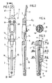
- valve body 1 Shown and described - initially with reference to FIGS. 1-4 - is a valve body 1 which can be used in particular in a dispenser, preferably in a pump dispenser.
- valve body 1 In Fig. 1 the valve body is shown in the opened state, as it is also injected.
- the valve body 1 consists essentially of a dispensing opening part 2 and a closure part 3, which via film joints 4, 5 are interconnected so that the valve body 1 can be injection molded in one piece.
- the closure part 3 forms a check valve 6. This serves to close off a ventilation duct 8.
- a groove-like recess 8 is formed in the dispensing opening part 2, which connects the ventilation opening 7 to the check valve 6.
- the closure tongue 17 is provided with an opening 7.
- the check valve 6 rests on a valve seat 9 which is formed in the dispensing opening part 2.
- the check valve 6, as can be seen in FIG. 2, is injection molded in an excellent manner with regard to its closed state, so that in the closed state (FIG. 3) there is a pretension with which the check valve 6 rests on the valve seat.
- the check valve 6 is molded in such a way that it encloses an angle alpha of, for example, 10 ° with respect to a plane E1 (which coincides here with the parting plane of the two valve parts 2, 3).
- valve body 1 is designed to be elongated, for fitting into a donor neck, as will be described further below with reference to FIGS. 7 and 8.
- the initial geometric shape of the valve body is an elongated round body. This is longitudinally divided in the middle, but connected at one end, via the film hinges 4 and 5 mentioned.
- the ventilation path and the check valve (in the embodiments) are in the folding level or immediately adjacent to it 1 - 4, 7, 8 and 9).
- the donation opening part forms a flow path 12 in cooperation with an inner wall 10 of a donor neck 11.
- a further groove-shaped recess 13 is formed in the dispensing opening part 2, opposite the groove-shaped recess 8.
- the groove-shaped recess 13 is not closed towards the inside of the dispenser in the closed state, but goes into a holder seat 14 for a suction pipe 15 (See, for example, FIGS. 7 and 8 again).
- a semi-cylindrical recess is provided in the dispensing opening part and the closing part 3. These cutouts open in the middle between the film joints 4 and 5.
- the dispensing opening part 2 and the closure part 3 can be latched in the locked state by means of locking pins 15, 16.
- a locking tongue 17 of the locking part 3, in which locking tongue the ventilation opening 7 and a locking knob 18 is formed, is designed to oscillate freely, with an impressed bias in the locked state.
- the closing tongue 17, in the same way as the check valve 6, is injection-molded in cross-section at an angle to the plane E1, likewise with an angle alpha of approximately 8-12 ° in the exemplary embodiment.
- the check valve 6 consists in particular of a flexible valve strip.
- the ventilation path which is interrupted by the check valve 6 continues to the inside of the dispenser beyond the check valve 6. And in the same way through recesses 21, 22 open to the outside, which merge into one another. Again in cooperation with the inner wall 10 of the donor neck 11, a closed flow path also results in this regard.
- the top view according to FIG. 4 shows the mobility of the locking tongue 17 between a closed position and an open position.
- a central axis a of the holder seat 14 runs essentially parallel or in the exemplary embodiment coincides with a parting plane T between the closure part 3 and the dispensing opening part 2.
- the ventilation opening 7 is formed in a cap 23 which, together with a housing 24, forms a dispenser.
- the ventilation opening 7 is covered here by the check valve 6, which extends essentially perpendicular to the parting plane T in the exemplary embodiments in question. Accordingly, the ventilation path in the closure part 3 or in cooperation with the dispensing opening part 2 has ceased to exist.
- valve body 1 according to the exemplary embodiments in FIGS. 5 and 6 has a further locking knob 25, which closes an outlet opening 26 in the dispenser neck 11 from the inside.
- the dispenser neck 11 is formed in the region of the outlet opening 26 and from there down to the inside of the dispenser with such a large inner diameter d that the closure tongue 17 can move freely between a closed position and a dispensed position.
- the head-side end of the dispensing opening part 2 is formed with a cross-sectionally sloping surface 27 for contacting a correspondingly extending section of the inner wall 10 of the donor neck 11.
- the slant 27 causes the locking knobs 25 to be inserted without damage during assembly.
- the swingability of the locking tongue 17 is due to a clear reduction in cross-section between an area in which the locking pins 15, 16 and the locking pin receptacles 19, 20 are formed and the area of the locking tongue 17.
- a rib 17 ' is provided to stiffen the transition. 5a and 6a show an oscillating movement of the locking tongue 17 between a closed position and a dispensing position.
- FIG. 5 shows the suction state after an actuation. Outside air is sucked in through the ventilation opening 7, which enables the dispenser housing 24 designed as a squeeze bottle to be reset after a pump operation.
- the actuation state is indicated in FIG. 6.
- a force is exerted on the dispenser housing 24 in accordance with the arrows b and c, which leads to a squeezing together.
- a pressure increase is achieved in the intermediate space 25.
- This pressure acts on the cartridge 36 and into the interior of the cartridge 36 through the passage opening 27 in the bottom of the cartridge. The pressure propagates to the bottom 29 of the refill 28 and pushes it up.
- the pressure increase in the room 25 also has the result that pressure is applied to the check valve from the inside and the ventilation opening 7 is thus closed. It is ensured that the pressure increase is used to dispense fluid from the dispenser.
- a flow connection is provided between the space 25 and the space 25 ', which is not shown in detail in the drawing.
- the cap 23 forms a dispenser neck 11 with an outlet opening 26 directed at right angles to a vertical axis of the dispenser. Otherwise, essentially the same conditions result as described above for the exemplary embodiments according to FIGS. 5 and 6. Here, however, the air suction is carried out by the closure part 3 itself. After pressure relief, the closure part 3 rests on the through opening 29 in a sealing manner. At the same time, the airway from the outlet opening 26 is opened inwards. The air in the suction state continues to flow through the flow channel 31 between the inner wall 10 and an outer wall of the closure part 3 through the opening 7 and the flow path 32 formed due to the recess 8 to the check valve 6.
- the check valve 6 is raised by the pressure and the air continues to flow through the sections 33 and 35 of the flow path formed in the closure part 3 into the interior of the dispenser .
- the closure flap 23 here forms a cylindrical jacket 34 which is open at the bottom and extends so far that the flow path 12 is closed to the outside. There can be no "short circuit" to the inside of the donor. Rather, the content of the dispenser, for example a liquid, must travel through the dip tube 39. Otherwise, with regard to the dispensers shown only partially in FIGS. 7 and 8, the same function results as with the dispensers described above.
- the dispenser according to FIG. 8 is provided with an upward extension in the flow paths 12 and 31, so that the outlet opening 26 is located approximately in the region of a central axis of the dispenser or in any case in the region a central axis of the cap 23.
- the cartridge 36 consists in detail of a cartridge container (identified by the reference symbol line of the reference symbol 36) and the refill pack 28 or the cartridge bag 28.
- the cartridge bag 28 merges into a closing part 28 'which is relatively rigid.
- the end part 28 ' lies on the edge (28'') on a circumferential edge 36' of the cartridge container and is firmly connected to it, for example glued.
- An upper ventilation opening 37 is formed in the end part 28 '. However, it is also conceivable to provide more than one upper ventilation 37.
- the space between an inner wall of the cartridge container 36 and an outer wall of the cartridge bag 28 can be vented through the upper opening 37 and the lower opening 27.
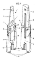
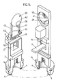
- valve body 1 in the embodiment according to FIGS. 1-4 in perspective, in the separated state.
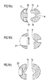
- valve body 1 shows different cross-sectional representations through the valve body 1 according to FIG. 9 or according to FIGS. 1-4.
- the essentially circular structure can be seen in each case.
- the check valve part 6 can freely withdraw into the recess 21.
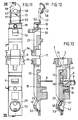
- valve body 1 consisting of the two valve body parts, the closure part 3 and the dispensing opening part 2, can be inserted into an adapter neck 48 of an adapter 46, which in turn is inserted into the container neck 47 (cf. FIGS. 15 and 16). Between the adapter neck 48 and the container neck 47 there is a space into which air slots 49 open to ventilate the container 24.
- the valve body 1 is seated in a cap forming the dispenser neck 11, which can be closed with a slide 57.
- the valve body consists of the two pluggable valve body parts, dispensing opening part 2 and closure part 3, which are integrally connected to one another by means of film hinges 4, 5.
- the closure part 3 has a closure member 17, which has a hemispherical closure head 42, which by means of two tongues 17 ' is formed on the closure part 3 via two spring joints 52.
- the hemispherical closure head 42 is prestressed in a spherical cap 41, which forms the valve seat for the product outlet valve.
- the cap is assigned to the dispensing opening part 2 and has two openings 29, 53.
- the filling material outlet opening 29 adjoins a groove-shaped recess 13, which, in the installed state, forms a flow path for the filling material with the neck inner wall 10.
- the further dispensing opening 53 forms the exit path for the filling material from the dispenser head.
- a pressure is built up inside the dispenser housing 24, it continues through the flow path and acts on the closure head 42 so that it lifts off the dispensing opening 29 or 53, the spring joints 52 taking effect.
- the closure head 42 moves into a chamber 43.
- the change in volume which is forced on the chamber 43 can be compensated for by a compensation opening 59 which is assigned to the portion of the closure head 42 which closes the dispensing opening 53.
- the hemispherical closure head 42 has a trough 58.
- the dispensing opening 53 is made in two parts. The two-part design is brought about by a bolt which separates the dispensing opening 53 parallel to the direction of extension and which closes the compensating opening 49 in the spherical cap 41 when the closure head 42 is in the bearing position.
- the displaced volume is replaced by air.
- This air flows through the flow channel 31 through the dispensing head and passes through a valve seat 9, which is assigned to the closure part 3, into a recess 21, which is connected to the air slots 49 of the adapter 46.
- the air inlet valve formed by the valve seat 9 and a closure tongue 6 assigned to the dispensing opening part 2 protrudes laterally from the essentially circular valve body.
- the recess 21 forms an air duct together with the inner neck wall 10 of the donor neck 11.
- the adapter 46 forms the connecting piece for the filling material flow from the cartridge bag 28 to the valve body 1.
- the valve body is seated in the neck 48 of the adapter 46, the valve body 1 being supported with its mounting seat 14 on an insert fit 62 of the adapter 46.
- the insert fit 62 is formed by an area of the neck 48 with a smaller cross section.
- the cartridge bag 28 is attached to the lower neck area of the adapter 46.
- the neck 48 of the adapter has a smaller outside diameter than the inside diameter of the neck 47 of the container 24.
- the free space between the adapter neck 48 and the container neck 47 forms an air channel for ventilation of the container.
- the adapter In addition to the formation of the air duct, the adapter also has the task of holding the cartridge bag 28 in the container neck 47.
- the adapter has a collar 60, the diameter of which is larger than the inside diameter of the container neck 47 and which rests on the upper edge of the container neck 47.
- the collar is adjoined on the neck side by a collar 63, the outside diameter of which corresponds to the inside diameter of the neck 47, so that the adapter is seated in a form-fitting and centered manner in the neck.
- the air passage between the valve body, here the recess 21, and the container formed by louvers 49 which are associated with the collar 63.
- the adapter 46 is inserted with its collar 60 into a recess in the cap 11, an annular groove 61 being formed on the collar 60 and connecting the air slots 49 with the recess 21. This ensures the ventilation connection between the air inlet valve and the interior of the container.
- the adapter is not centered by a collar 63 in the neck 47 of the container 24, but that the adapter 46 with its collar 60 lies in a form-fitting manner in an annular opening in the cap.
- the cap can also partially extend into the adapter neck 48.
- the valve body is preferably produced in an unfolded position by an injection molding machine.
- the automat is designed so that when the valve body parts are removed from the mold, they are bent around the film hinges 4, 5 and folded into the position shown in FIG. 13.
- the tip of the closure tongue 6 runs on a run-out curve 50 of the closure part and thus comes into a prestressed support on the valve seat 9.
- the connection between the dispensing opening part 2 and the closure part 3 is established by the locking pin 15, which is locked with a pin recess 19.
- the locking pin 15 is mushroom-shaped in cross-section, the mushroom-shaped head having a slightly larger diameter than the pin recess 19.
- the separating surface T formed by the two valve body parts 2, 3 also serves in this embodiment for Separation of product channels and air channels, the product channels being assigned to the dispensing opening part 2 and the air channels being assigned to the closure part 3.
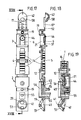
- FIGS. 17-22 A fourth embodiment of the valve body is shown in FIGS. 17-22. As described in relation to the third embodiment, this embodiment also has a hemispherical closure head 42 which lies in a carrot 41 and forms the filling material outlet valve. The filling material exits through the flow path 12 into a dividing flow path 45 which is formed together by the inner wall of the neck and two parallel grooves, both paths reuniting in front of the cap 41. These two parallel product paths 45 enclose an air channel 56, which adjoins the seat of the air inlet valve and which opens into a transverse channel 55, which in turn opens into an air flow channel assigned to the dispensing cap.
- the air inlet valve is formed by a closure member 6, a closure flap 44 being formed on a closure tongue and resting on a valve seat 9.
- the closure member 6 is connected to a spring joint 51 on the closure part 3.
- Both the filling material outlet valve and the air inlet valve are formed in the parting plane T.
- the air inlet duct crosses twice the parting plane, once by forming the valve seat and again by a transverse duct 55 which is connected to the flow duct 31 by the groove 56.
- the transverse channel 55 passes through a free space formed by the closure member tongues 17 '.
- grooves arranged on the valve body surface form in cooperation with the inner wall 10 of the dispensing neck 11 grooves in which air or product is transported.
Landscapes
- Engineering & Computer Science (AREA)
- Mechanical Engineering (AREA)
- General Engineering & Computer Science (AREA)
- Containers And Packaging Bodies Having A Special Means To Remove Contents (AREA)
Applications Claiming Priority (4)
| Application Number | Priority Date | Filing Date | Title |
|---|---|---|---|
| DE4005881 | 1990-02-24 | ||
| DE4005881 | 1990-02-24 | ||
| DE4018147 | 1990-06-06 | ||
| DE19904018147 DE4018147A1 (de) | 1990-02-24 | 1990-06-06 | Ventilkoerper |
Publications (2)
| Publication Number | Publication Date |
|---|---|
| EP0444313A2 true EP0444313A2 (fr) | 1991-09-04 |
| EP0444313A3 EP0444313A3 (en) | 1992-10-07 |
Family
ID=25890501
Family Applications (1)
| Application Number | Title | Priority Date | Filing Date |
|---|---|---|---|
| EP19900125625 Withdrawn EP0444313A3 (en) | 1990-02-24 | 1990-12-28 | Valve body |
Country Status (6)
| Country | Link |
|---|---|
| US (1) | US5190190A (fr) |
| EP (1) | EP0444313A3 (fr) |
| CA (1) | CA2036924A1 (fr) |
| CS (1) | CS31491A2 (fr) |
| DE (1) | DE4018147A1 (fr) |
| HU (1) | HUT56518A (fr) |
Cited By (1)
| Publication number | Priority date | Publication date | Assignee | Title |
|---|---|---|---|---|
| WO1994026612A3 (fr) * | 1993-05-15 | 1995-01-19 | Henkel Kgaa | Bouchon doseur |
Families Citing this family (41)
| Publication number | Priority date | Publication date | Assignee | Title |
|---|---|---|---|---|
| EP0615460B1 (fr) * | 1991-12-02 | 1999-06-02 | PY, Daniel | Dispositif d'application d'un medicament sur l'oeil |
| US5267986A (en) | 1992-04-06 | 1993-12-07 | Self-Instill & Co., Inc. | Cartridge for applying medicament to an eye from a dispenser |
| US5439178A (en) * | 1993-06-24 | 1995-08-08 | The Procter & Gamble Company | Pump device including multiple function collapsible pump chamber |
| US5664703A (en) * | 1994-02-28 | 1997-09-09 | The Procter & Gamble Company | Pump device with collapsible pump chamber having supply container venting system and integral shipping seal |
| US5518147A (en) * | 1994-03-01 | 1996-05-21 | The Procter & Gamble Company | Collapsible pump chamber having predetermined collapsing pattern |
| SE501683C2 (sv) * | 1994-03-15 | 1995-04-24 | Billy Nilson | Självstängande utmatningsanordning |
| US5561901A (en) * | 1994-10-06 | 1996-10-08 | The Procter & Gamble Company | Assembly process including severing part of integral collapsible pump chamber |
| US5476195A (en) * | 1994-10-06 | 1995-12-19 | Procter & Gamble Company | Pump device with collapsible pump chamber and including dunnage means |
| DE19513670B4 (de) * | 1995-04-11 | 2006-03-16 | Behr Gmbh & Co. Kg | Klappe für einen Luftführungskanal |
| FR2735357B1 (fr) * | 1995-06-14 | 1997-12-05 | Py Daniel C | Instillateur oculaire double |
| DE29514554U1 (de) * | 1995-09-01 | 1995-11-16 | Hako-Werke Gmbh & Co, 23843 Bad Oldesloe | Fahrbare Naßreinigungsmaschine |
| DE19613875A1 (de) * | 1996-04-06 | 1997-10-09 | Behr Gmbh & Co | Klappe für einen Luftführungskanal |
| GB9626960D0 (en) * | 1996-12-27 | 1997-02-12 | Glaxo Group Ltd | Valve for aerosol container |
| FR2852933B1 (fr) * | 2003-03-24 | 2005-05-13 | Airlessystems | Distributeur de produit fluide. |
| DE10361069A1 (de) * | 2003-12-22 | 2005-07-21 | Kurt Wiederkehr | Vorrichtung zum Ausbringen von zumindest einer Substanz |
| EP1598118A1 (fr) * | 2004-05-21 | 2005-11-23 | The Procter & Gamble Company | Pompe pour distributeur de liquide |
| US7306129B2 (en) * | 2005-11-03 | 2007-12-11 | Stewart Swiss | One way valve assembly |
| FR2884157B1 (fr) * | 2005-04-08 | 2007-07-06 | Airlessystems Soc Par Actions | Tete de distribution |
| EP1874377B1 (fr) * | 2005-04-25 | 2014-11-12 | Dolhay Klinika Egészségügyi KFT. | Buse de traitement |
| TW200733993A (en) * | 2005-11-03 | 2007-09-16 | Reseal Internat Ltd Partnership | Continuously sealing one way valve assembly and fluid delivery system and formulations for use therein |
| US7874467B2 (en) * | 2005-11-03 | 2011-01-25 | Reseal International Limited Partnership | Metered drop push button dispenser system |
| TW200735906A (en) * | 2005-11-03 | 2007-10-01 | Rseal Internat Ltd Partnership | Continuously sealing one way valve assembly and fluid delivery system and formulations for use therein |
| JP4434138B2 (ja) * | 2005-12-20 | 2010-03-17 | 株式会社デンソー | バルブユニットの製造方法及び組付方法 |
| DE102006012302A1 (de) * | 2006-03-15 | 2007-09-27 | Seaquist Perfect Dispensing Gmbh | Abgabevorrichtung |
| DE102007051980A1 (de) * | 2007-08-29 | 2009-03-05 | Seaquist Perfect Dispensing Gmbh | Abgabevorrichtung |
| DE102007051982A1 (de) * | 2007-08-29 | 2009-03-05 | Seaquist Perfect Dispensing Gmbh | Abgabevorrichtung |
| US20100286633A1 (en) * | 2008-02-05 | 2010-11-11 | Marx Alvin J | Precision Lid Retracting Eyedropper Device |
| US8286839B2 (en) * | 2008-08-12 | 2012-10-16 | Aptar Dortmund Gmbh | Dispensing device |
| GB0902626D0 (en) * | 2009-02-17 | 2009-04-01 | Farrar Peter A | Combination pack for personal care products |
| JPWO2010150425A1 (ja) * | 2009-06-26 | 2012-12-06 | 株式会社システムコミュニケーションズ | 柔軟パウチ容器用ホルダー |
| IT1395730B1 (it) * | 2009-07-31 | 2012-10-19 | Lumson Spa | "contenitore associabile a pompe airless e metodo per la sua realizzazione" |
| WO2011126569A1 (fr) * | 2010-04-06 | 2011-10-13 | Reseal International Limited Partnership | Système de distribution pour distribution de volumes mesurés de substances fluides pures ou stériles |
| GB2483087A (en) * | 2010-08-26 | 2012-02-29 | Breeze Product Design Ltd | Refillable Dispenser with Deformable Membrane |
| JP5667010B2 (ja) * | 2011-06-09 | 2015-02-12 | 株式会社吉野工業所 | 吐出容器 |
| CA2860271C (fr) | 2011-12-26 | 2018-12-04 | Yoshino Kogyosho Co., Ltd. | Recipient pressable |
| RU2591944C2 (ru) * | 2012-01-20 | 2016-07-20 | ДР. ПИ ИНСТИТЬЮТ ЭлЭлСи | Устройство с совместно отформованным укупорочным средством, камерой хранения и противоразбрызгивающим средством и соответствующий способ |
| US9045268B2 (en) * | 2012-07-25 | 2015-06-02 | Gojo Industries, Inc. | Collapsible container and dispenser employing a collapsible container |
| FR3004429B1 (fr) * | 2013-04-16 | 2015-11-27 | Rexam Dispensing Sys | Ensemble comprenant un flacon remplissable et une source de produit |
| WO2015021015A1 (fr) | 2013-08-05 | 2015-02-12 | Johns Nicholas P | Procédé et appareil permettant d'administrer un fluide à un individu |
| TWI651070B (zh) * | 2013-12-06 | 2019-02-21 | 瑞士商拜耳保健消費品股份有限公司 | 用於施配可流動材料之施配器 |
| FR3019763B1 (fr) * | 2014-04-10 | 2019-11-29 | Gb Developpement | Dispositif distributeur de fluide et valve munie d'un moyen de rappel |
Family Cites Families (8)
| Publication number | Priority date | Publication date | Assignee | Title |
|---|---|---|---|---|
| US2599499A (en) * | 1945-02-16 | 1952-06-03 | Goetaverken Ab | Spring plate valve |
| US3057373A (en) * | 1959-10-19 | 1962-10-09 | Parker Hannifin Corp | Flow limiting valve |
| US3269609A (en) * | 1964-12-31 | 1966-08-30 | Bridgeport Metal Goods Mfg Co | Compositie container cap and outer collar |
| US4098434A (en) * | 1975-06-20 | 1978-07-04 | Owens-Illinois, Inc. | Fluid product dispenser |
| US4102476A (en) * | 1977-02-22 | 1978-07-25 | Ciba-Geigy Corporation | Squeeze bottle dispenser with air check valve on cover |
| US4179051A (en) * | 1977-08-01 | 1979-12-18 | Ryder International Corporation | One-piece check valve for use in a fluid dispenser |
| US4273272A (en) * | 1979-11-13 | 1981-06-16 | William B. Anderson | Liquid dispenser |
| CA1126614A (fr) * | 1981-07-06 | 1982-06-29 | Robert J. Demers | Soupape a languette |
-
1990
- 1990-06-06 DE DE19904018147 patent/DE4018147A1/de not_active Withdrawn
- 1990-12-28 EP EP19900125625 patent/EP0444313A3/de not_active Withdrawn
-
1991
- 1991-02-08 CS CS91314A patent/CS31491A2/cs unknown
- 1991-02-14 US US07/656,229 patent/US5190190A/en not_active Expired - Fee Related
- 1991-02-22 HU HU91601A patent/HUT56518A/hu unknown
- 1991-02-22 CA CA 2036924 patent/CA2036924A1/fr not_active Abandoned
Cited By (1)
| Publication number | Priority date | Publication date | Assignee | Title |
|---|---|---|---|---|
| WO1994026612A3 (fr) * | 1993-05-15 | 1995-01-19 | Henkel Kgaa | Bouchon doseur |
Also Published As
| Publication number | Publication date |
|---|---|
| US5190190A (en) | 1993-03-02 |
| HUT56518A (en) | 1991-09-30 |
| CS31491A2 (en) | 1991-09-15 |
| DE4018147A1 (de) | 1991-08-29 |
| CA2036924A1 (fr) | 1991-08-25 |
| EP0444313A3 (en) | 1992-10-07 |
Similar Documents
| Publication | Publication Date | Title |
|---|---|---|
| EP0444313A2 (fr) | Corps de soupape | |
| DE69503883T2 (de) | Flüssigkeitsspender mit nachfüllbehälter | |
| DE2901717C2 (fr) | ||
| EP0492363B1 (fr) | Valve d'aspiration et/ou de refoulement pour une pompe de dosage ou de pulvérisation de produits liquides, à basse viscosité et pâteux | |
| DE69803361T2 (de) | Vorrichtung zur abgabe vom fliessfähigen produkt mit verschlussvorrichtung | |
| DE602004000860T2 (de) | Sprühvorrichtung | |
| EP0144879B1 (fr) | Distributeur pour matériaux pâteux, notamment distributeur de pâtes dentifrices | |
| EP0738543B1 (fr) | Pompe de distribution en matière plastique pour matière pâteuse | |
| DE69323502T2 (de) | WEGWERFFLüSSIGKEITSPUMPE AUS KUNSTSTOFF | |
| DE2739893A1 (de) | Zusammendrueckbare flasche aus elastisch verformbarem material | |
| EP0368062A1 (fr) | Distributeur de produits pâteux | |
| DE19756442A1 (de) | Spender für Medien | |
| EP2688679B1 (fr) | Distributeur de produits liquides à pâteux | |
| EP3911448B1 (fr) | Élément adaptateur, distributeur ainsi que réserve utilisée avec un distributeur | |
| DE69903449T2 (de) | Behälterventil | |
| DE19933330A1 (de) | Spender für Medien | |
| EP0390974B1 (fr) | Fermeture pour récipient flexible contenant des liquides | |
| DE69626184T2 (de) | Herstellungsverfahren für eine abgabeflasche mit einem flexiblen beutel | |
| DE4212434A1 (de) | Anordnung zum Nachfüllen eines Behälters | |
| DE69120429T2 (de) | Dosier- und ausgiessvorrichtung | |
| EP1871539B1 (fr) | Distributeur utilise pour la distribution des masses fluides et pateuses | |
| DE69404459T2 (de) | Tragbares gerät zur abgabe einer flüssigkeit | |
| WO2007122087A1 (fr) | Distributeur pour distribuer des masses de consistance liquide à pâteuse | |
| DE602004003951T2 (de) | Steuerventil für einen fluidproduktspender und solch ein ventil umfassender fluidproduktspender | |
| DE69903435T2 (de) | Spender für abgabe einer viskosen substanz, z.b. einer antiseptischen flüssigkeit, und behälter für solchen spender |
Legal Events
| Date | Code | Title | Description |
|---|---|---|---|
| PUAI | Public reference made under article 153(3) epc to a published international application that has entered the european phase |
Free format text: ORIGINAL CODE: 0009012 |
|
| AK | Designated contracting states |
Kind code of ref document: A2 Designated state(s): AT BE CH DE DK ES FR GB GR IT LI LU NL SE |
|
| PUAL | Search report despatched |
Free format text: ORIGINAL CODE: 0009013 |
|
| AK | Designated contracting states |
Kind code of ref document: A3 Designated state(s): AT BE CH DE DK ES FR GB GR IT LI LU NL SE |
|
| 17P | Request for examination filed |
Effective date: 19930212 |
|
| 17Q | First examination report despatched |
Effective date: 19940119 |
|
| STAA | Information on the status of an ep patent application or granted ep patent |
Free format text: STATUS: THE APPLICATION IS DEEMED TO BE WITHDRAWN |
|
| 18D | Application deemed to be withdrawn |
Effective date: 19940928 |