EP0444242A1 - Rail grinding machine - Google Patents
Rail grinding machine Download PDFInfo
- Publication number
- EP0444242A1 EP0444242A1 EP90120502A EP90120502A EP0444242A1 EP 0444242 A1 EP0444242 A1 EP 0444242A1 EP 90120502 A EP90120502 A EP 90120502A EP 90120502 A EP90120502 A EP 90120502A EP 0444242 A1 EP0444242 A1 EP 0444242A1
- Authority
- EP
- European Patent Office
- Prior art keywords
- rail
- grinding
- belt
- longitudinal direction
- deflection
- Prior art date
- Legal status (The legal status is an assumption and is not a legal conclusion. Google has not performed a legal analysis and makes no representation as to the accuracy of the status listed.)
- Granted
Links
Images


Classifications
-
- B—PERFORMING OPERATIONS; TRANSPORTING
- B24—GRINDING; POLISHING
- B24B—MACHINES, DEVICES, OR PROCESSES FOR GRINDING OR POLISHING; DRESSING OR CONDITIONING OF ABRADING SURFACES; FEEDING OF GRINDING, POLISHING, OR LAPPING AGENTS
- B24B21/00—Machines or devices using grinding or polishing belts; Accessories therefor
- B24B21/04—Machines or devices using grinding or polishing belts; Accessories therefor for grinding plane surfaces
- B24B21/06—Machines or devices using grinding or polishing belts; Accessories therefor for grinding plane surfaces involving members with limited contact area pressing the belt against the work, e.g. shoes sweeping across the whole area to be ground
- B24B21/08—Pressure shoes; Pressure members, e.g. backing belts
-
- E—FIXED CONSTRUCTIONS
- E01—CONSTRUCTION OF ROADS, RAILWAYS, OR BRIDGES
- E01B—PERMANENT WAY; PERMANENT-WAY TOOLS; MACHINES FOR MAKING RAILWAYS OF ALL KINDS
- E01B31/00—Working rails, sleepers, baseplates, or the like, in or on the line; Machines, tools, or auxiliary devices specially designed therefor
- E01B31/02—Working rail or other metal track components on the spot
- E01B31/12—Removing metal from rails, rail joints, or baseplates, e.g. for deburring welds, reconditioning worn rails
- E01B31/17—Removing metal from rails, rail joints, or baseplates, e.g. for deburring welds, reconditioning worn rails by grinding
- E01B31/175—Removing metal from rails, rail joints, or baseplates, e.g. for deburring welds, reconditioning worn rails by grinding using grinding belts
Definitions
- the invention relates to a rail grinding machine, comprising a grinding device which can be raised and lowered on a machine frame and which can be moved in the longitudinal direction on one or both rails of a track and can be adjusted relatively and approximately transversely thereto, which has a driven deflection roller and at least one at a distance pressure roller arranged for this purpose for a grinding belt driven in the rail longitudinal direction.
- a rail grinding machine is known from EP-A 0 110 246, which can be moved on one or both rails of a track in the longitudinal direction of the rail and, for grinding processing of the rail tread, essentially runs all around via a drive roller and a pressure roller driven grinding belt includes.
- the two rollers can be braced against one another and can be pivoted together on a machine frame with respect to the longitudinal direction of the rails.
- This grinding machine is used essentially for the profile-correct grinding of welding beads or the like, such as those that occur, for example, in connection welding or during repair work on track rails.
- the invention is therefore based on the object of designing the rail grinding machine of the generic type in such a way that, while maintaining uniform wear of the grinding belt, it is possible to eliminate irregularities, in particular from wave and corrugation valleys to approximately the zero line with a uniform grinding pattern.
- the deflection of the sanding belt is formed on the side facing the rail running surface by means of a pressing device which has at least two pressure rollers arranged at a distance from one another in the longitudinal direction of the rail, a deflection roller arranged offset in the vertical direction between the two pressure rollers, and a drive belt encircling the two pressure rollers and the deflection roller and pressing the grinding belt against the rail running surface, and that the upper deflection roller and the deflection roller and pressure rollers of the pressing device are each rotatably mounted on a first carrier plate about their axes oriented transversely to the longitudinal direction of the rail and a second Carrier plate by means of correspondingly arranged hinges is pivotally mounted on a carrier element, such that the two carrier plates with the parts mounted thereon can be pivoted relative to the carrier element in order to achieve an oblique position of the grinding belt which is oriented in relation to the longitudinal direction of the rail and is known per se.
- the radii provided at the transition from the running surface of the rail to the side or inner flank can be ground with a second grinding belt arranged approximately transversely to the longitudinal direction of the rail.
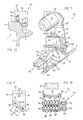
- FIG. 1 shows a side view
- FIG. 2 shows a rail grinding machine 100 according to the line II-II shown in FIG. 1 in a sectional view, which on a track 1 formed essentially from two rails arranged in parallel spacing from one another with no closer represented means, for example by an appropriately arranged, electromotive drive unit in the arrow direction X or X 'can be moved forward or backward.
- the rail grinding machine 100 essentially comprises a machine frame, designated in its entirety by 25, a first grinding device, designated in its entirety by 50, and a second grinding device, designated in its entirety by 75.
- the machine frame 25 and the two grinding devices 50, 75 are described in detail below.
- the machine frame 25, which is designed as a structural unit and is arranged on a base frame 45, essentially comprises, as shown in FIG. 1, two frame parts 15 and 15 'arranged at a distance from one another. On one side of the respective frame part 15, 15 ', a lifting or lowering device 10, 10', which is arranged at a short distance from it and is shown schematically, is provided. A first frame 20 and a second frame 30 and a carrier element 40 for the first grinding device 50 are further arranged between the two frame parts 15, 15 '.
- the base frame 45 for the rail grinding machine 100 which is essentially formed from longitudinal and cross members (not shown in more detail), is mounted on the rails 1 'by means of roller and guide roller sets 46, 46' and 47, 47 'and 48.48' mounted on the longitudinal members. 1 "of the track 1 arranged.
- the individual lifting or lowering device 10, 10 ' which is operatively connected to the frame part 15 or 15' by means of corresponding fastening elements 14, 14 'and 44, 44' and can be actuated, for example, by an associated motor 13, 13 ', each has a correspondingly assigned standing column 11, 11 '. In the lower area, the two standing columns 11, 11 'are each fork-like for mounting a roller 12, 12' oriented essentially transversely to the track 1.
- the machine frame 25 essentially comprising the elements 10, 20, 30, 40 and 50 can be raised relative to the track 1 in the direction of the arrow Z and lowered in the direction of the arrow Z'.
- the machine frame 25 with the rollers 12, 12 ' is parked on the floor.
- the complete machine frame 25 can be moved across the track.
- the frame part 15 has two supports 16, 16 'which are arranged at a distance from one another transversely to the rail or transport direction and which are connected to one another by cross struts 18, 18', 18 ". The part shown in FIG.
- the first frame 20 has two side parts 22, 22 ′ which are arranged at a distance from one another and which are connected to one another in the upper region by a carrier element 21.
- guides 23, 23 ' arranged at a distance from one another and oriented in the vertical direction and corresponding guides 24, 24' on the side part 22 'are provided on the side part 22.
- a schematically illustrated bearing 35 and 36 is arranged in the lower region of the individual side part 22 and 22 '.
- the frame frame 20 is articulated on one side to the frame part 15 and on the other side to the frame part 15 'by means of the bearings 35, 36 or axle body forming a pivot axis 35', 36 '.
- the second frame 30 comprises two spaced-apart side parts 31, 31 '(FIG. 1) which are connected to one another by a carrier element 32.
- FIG. 1 shows a spindle 28, which is fastened to the carrier element 32 of the second frame 30 in a manner not shown, and which is operatively connected to a handwheel 29 resting on the carrier element 21 of the first frame 20.
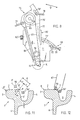
- the second grinding device 75 which is arranged at one end of the base frame 45 and is shown schematically in FIG. 1, is fastened to the base frame 45 with a correspondingly designed holding element 73 and comprises a drive motor 76 arranged essentially on a carrier plate 77 for a second, transverse to the rail body 1 'Oriented grinding belt 87.
- the second grinding device 75 is pivotally mounted on the holding element 73 about an axis 69' of a correspondingly arranged axle body 69, as indicated in FIGS. 7 and 8 with the arrow direction S, S '.
- an adjusting device designated as a whole by 80 and arranged on plates 71, 81.
- the adjusting device 80 which is designed as a known cross slide, comprises a first slide body 82 which is operatively connected to an adjusting screw 82 'and a second carriage body 83 which is operatively connected to an adjusting screw 83'.
- a first deflection roller 85 At the upper end of the carrier plate 77 is a first deflection roller 85 and at the lower end of the grinding device 75 a deflection device 95 for the second grinding belt 87 is arranged.
- a protective element 88 covering the grinding belt 87 for the operating personnel is provided on the carrier plate 77.
- the second grinding device 75 and its function will be described later in detail with reference to FIGS. 7 to 12.
- FIG. 2 shows a section of the rail grinding machine 100 shown in a sectional view along the line II-II in FIG. 1, and one can see the one frame part 15 ', the first frame 20, the second frame 30 and the carrier element 40 with the first grinding device 50 arranged laterally thereon.
- the frame part 15 ' is formed by the two spaced-apart supports 17, 17', which are connected to one another by the approximately arch-shaped cross strut 19 and by further cross struts 19 'and 19 "and on the schematically illustrated base frame 45 in a manner not shown
- the individual roller and guide roller sets shown in FIG. 1 and essentially mounted on the base frame 45 are not shown in FIG.
- the first frame 20, essentially formed from the two plate-like side parts 22, 22 ′ and the connecting piece 21, is shown broken away in the upper region (FIG. 2) in order to better illustrate the second frame 30.
- Connecting piece 37 is provided, which is designed as a counter bearing for a handwheel 39 which is operatively connected to a spindle 38.
- the housing-like support element 40 is provided on one side with a plate 43 on which, by means of correspondingly designed support plates 58 and 58 ', the first grinding device 50 with the parts 51, 52 and 53, 53' and 56 shown schematically in FIG. 56 ', 56 ".
- the first carrier plate 58 is mounted on the second carrier plate 58' by means of an axle body 65, which is shown schematically in FIG. 2.
- the height of the second frame 30 together with the carrier element 40 and the first grinding device 50 mounted on the side thereof, as shown in FIG. 2, can be adjusted in the direction of the arrows Z and Z ' .
- the second frame 30 is guided with the rails 26, 26 'and 27, 27' in the guides 23, 23 'and 24, 24' provided on the first frame 20.
- the carrier element 40 together with the first grinding device 50 arranged thereon can be adjusted relative to the first and second frame frames 20, 30 in the direction of the arrows Y and Y '.
- the carrier element 40 with the rails 41, 41' and 42, 42 ' is arranged in the guides 33, 33' and 34, 34 'of the second frame 30.
- This adjustment movement essentially serves to adjust the first grinding device 50 in relation to the corresponding rail body 1 ′ or 1 ′′ of the track 1.
- the first frame frame 20 which is mounted on the frame parts 15 and 15 'with the schematically illustrated axle body 35 and 36, and the elements 30 and 40 mounted thereon, as in FIG. 2 with the arrow direction Y "about the axis 35' and 36 ', are the axle body 35, 36 can be pivoted to achieve an approximately vertical adjustment of the grinding belt grinding angle.
- FIG 3 shows a further, schematically illustrated exemplary embodiment of the rail grinding machine 100, in which the first grinding device 50, which is mounted on the axle body 65, is mounted on one side of the carrier element 40 'and an analogously designed grinding device 150 is mounted on an axle body 165 on the other side is.
- the grinding device 150 essentially comprises the parts 158, 158 ', 151, 152, 153, 153' and 156, 156 ', 156 ".
- This further embodiment variant makes it possible that only the adjustment movement of the carrier element 40', indicated by the arrow direction Y or Y 'in FIG one or other rail body 1 'or 1 "can be ground without the need for laborious retrofitting.
- FIG. 4 shows, in a schematically represented side view, the first grinding device 50 and the carrier element 40 provided with the lateral rails 41, 41 'and 42, 42' and the plate 43 and the carrier plates 58 and 58 'arranged thereon for the first grinding device 50 can be seen
- the second carrier plate 58 ' is mounted on the plate 43 of the carrier element 40 by means of appropriately designed hinges 61, 61'.
- a schematically illustrated adjusting element 60 is arranged on the side opposite the hinges 61, 61 '.
- the second carrier plate 58 ' can thus pass through end-to-end replacement of the hinge bolts, not shown and designated, either on one pair of hinges 61, 61 'or on the other pair of hinges 62, 62'.
- the first support plate 58 which lies essentially against the second support plate 58 ', is arranged and held on the second support plate 58' by means of the axle body 65 and locking elements 63, 64 or screws 66, 66 'arranged at a distance from one another.
- the grinding device 50 comprises the deflection roller 51 for the grinding belt 52, which is mounted in the upper region on the first carrier plate 58 in a manner not shown and is driven by an electric motor 49 shown schematically in FIG. 5 in the direction of arrow 49 '.
- the pressing device 55 has at least two rollers 56, 56 ′ facing the rail surface 2 and arranged at a distance C from one another.
- a plurality of rollers 54 and 56, 56 'and 56 ", which are arranged at a distance from one another, are mounted on the first carrier plate 58.
- the center distance C between the two outer rollers 56 and 56" is of the order of 150 mm to 300 mm.
- rollers 56, 56 'and 56 "facing the rail tread 2 essentially serve as pressure rollers and the roller 54 as a deflection roller for a pressure belt 57 which wraps around these rollers.
- the rollers 54 and 56, 56' and 56" are also not with one External teeth shown in detail and operatively connected to each other by the pressure belt 57 provided with an internal toothing.
- the first carrier plate 58 with the parts 51, 52, 53, 53', 54, 56, 56 ', 56 "and 57 arranged thereon about the axis 65' of Axle body 65 can be pivoted relative to the second support plate 58 'fastened to the plate 43 of the support element 40 in the direction of the arrow X "(FIG. 1.4).
- FIG. 5 shows a top view of the first grinding device 50 and one can see the plate 43 fastened to the carrier element 40, the hinges 61, 61 'arranged and fastened on the plate 43 for the second first carrier plate 58' which is operatively connected thereto and the one on the second carrier plate 58 '. arranged and mounted on the axle body 65 first support plate 58.
- the adjusting member 60 On the opposite side of the hinges 61,61 'the adjusting member 60 is arranged, by means of which the two support plates 58,58' with the rollers 51,53,53 ', 54, 56 arranged thereon , 56 ', 56 "and the grinding belt 52 can be pivoted in the direction of the arrow Y" about the axis of the hinges 61, 61' (not shown).
- the adjusting member 60 has an adjusting screw 68 fastened to the plate 43 and a holding plate 67 fastened to the first carrier plate 58.
- the holding plate 67 penetrated by the adjusting screw 68 is designed with a correspondingly for the pivoting movement in the direction of arrow Y "of the two carrier plates 58, 58 ' Provide recess (not shown).
- FIG. 6 shows the grinding device 50 shown in plan view and pivoted relative to the carrier element 40 in the direction of arrow Y "and one can see the two carrier plates 58 and 58 'pivoted together about the axis of the hinges 61, 61' and essentially diagonally to the one to be ground Tread 2 of the rail body 1 'arranged grinding belt 52 of the grinding device 50.
- the schematically illustrated adjusting member 60 is designed such that the movement of the grinding device 50 in the direction of the arrow Y "takes place continuously and the grinding device 50 can be fixed in any position.
- the holding device 70 comprises a plate 71 provided with an arcuate slot 71 'for the fixing element 74, to which a holding element 73 formed from a plate 72, a web 72' and a bracket 72 "is fastened on one side.
- the holding element 73 serves essentially for fastening the entire grinding device 75 to the base frame 45.
- the holding plate 81 which is also mounted on the axle body 70 ', and the adjusting device designated as a whole by 80 is arranged thereon.
- the commercially available adjustment device 80 which is designed as a cross support, essentially comprises the first carriage body 83 with adjusting screw 83 'arranged on the holding plate 81 for fine adjustment oriented approximately vertically in the direction of the rail body 1', and the second carriage body 82 with adjusting screw 82 mounted on the first carriage body 83 'for the fine adjustment of the entire grinding device 75 oriented approximately transversely to the rail body 1'.
- the carrier plate 77 for the second grinding device 75 is fastened in the middle.
- a further plate 76 ′′ is arranged on the carrier plate 77, to which the motor 76 is fastened with a flange 76 ′ by a screw connection (not shown in more detail).
- the motor 76 is connected to the deflection roller 85 of the second grinding device 75 mounted on the other side of the carrier plate 77 is operatively connected.
- the second grinding device 75 shown in the direction of arrow B (FIG. 1) is shown in view and one can see the first, upper deflection roller 85, a second deflection roller 86 arranged at a distance from it, and a one arranged in the lower region on the carrier plate 77 attached deflection device 95 for the second grinding belt 87.
- the protective element 88 and partly the second slide body 82 with the set screw 82 'and the plate 71 with the arcuate slot 71' can be seen in FIG.
- a stop device 90 is arranged and fastened on the plate 71, which essentially comprises an adjusting spindle 91 and a stop 92.
- the pivoting movement of the grinding device 75 which is essentially guided in the slot 71 ', about the axis 69' in the arrow direction S 'can be set and limited by means of the stop device 90.
- the pivoting movement of the individual elements denoted by 5 in FIG. 7 and S ′ in FIG. 8, is essentially identical to one another.
- a locking element 78 is arranged in an arcuate elongated hole 78 'and at a distance from it a further locking element 79.
- the elements 78, 78 'and 79 are provided so that the motor 76, which is fastened to the plate 76 "with a flange 76', can be adjusted together with the plate 76" relative to the carrier plate 77 and by means of the elements 78, 79 in the desired position is fixable.
- FIG. 9 shows on a larger scale and in side view and FIG. 10 in view the deflection device 95 designated by the circle K (FIG. 8) for the grinding belt 87 of the second grinding device 75.
- the deflection device 95 comprises two holding plates 93 and 94 which are arranged at a distance from one another and which are connected to one another in the upper region by a bolt 99 designed as a spacer. One end of the bolt 99 is arranged and fastened in the first holding plate 93. At the other end, the bolt 99 penetrates the second holding plate 94 and is secured by means of a corresponding nut 99 '.
- the deflection device 95 is either fastened with the one holding plate 93 to the carrier plate 77 of the second grinding device 75 in a manner not shown in detail, or the holding plate 93 is designed as a section of the carrier plate 77. Furthermore, a plurality of rollers 97 'arranged at a distance from one another are mounted between the two holding plates 93, 94 on a first bolt 96 and a plurality of rollers 98' arranged at a distance from one another at a second bolt 96 '.
- rollers 97 ' each spaced on the two bolts 96, 96' by spacers 97 "and 98", form a first group of rollers 97 and the rollers 98 'form a second group of rollers 98 for deflecting the grinding belt, which is partially shown in FIG 87.
- the two bolts 96, 96 'penetrating the holding plates 93, 94 can be designed as threaded bolts.
- a centering device 110 shown schematically in FIG. 10, is preferably arranged on one side of the deflection device 95, which comprises a first, fork-like bearing piece 111 for a first centering roller 112 and a second, fork-like bearing piece 114 for a second centering roller 113.
- Roller ball bearings are preferably used as centering rollers 112 and 113.
- the parts are the individual parts 111, 112 and 113, 114 of the centering device 110 for better illustration shown rotated about the longitudinal axes of the bolts 96, 96 ', not shown and designated.
- the two bearing pieces 111, 113 are operatively connected in a manner not shown, for example by a screw connection with the respective bolt 96, 96 '.
- rollers 97 and 98 With the deflection device 95, due to the rollers 97 and 98 arranged at a distance from one another, sufficient heat dissipation of the heating occurring during the grinding process on the grinding belt 87 is ensured.
- Appropriately designed and dimensioned roller ball bearings can also be used as rollers.
- the edges 93 'and 94' of the two holding plates 93, 94 facing the rail body are, as shown in FIG. 9, of an arcuate shape with a corresponding radius A '.
- the two bolts 96, 96 'for the rollers are arranged at a distance from one another, the distance A of one bolt 96' relative to the other bolt 96 being correspondingly variable.
- the distance A is essentially dependent on the radius R or R 'to be ground on the rail body, the geometric arrangement of the two bolts 96, 96' to one another being described with reference to FIG. 11. At this point it should be pointed out that for the grinding of the radius R 'the deflection device 95 is to be arranged corresponding to the carrier plate 77 of the second grinding device 75 (not shown).
- FIG. 11 shows, as an exemplary embodiment and application example, a section of the rail body 1 'shown in a sectional view and designed as a grooved rail and the running surface 2 oriented in the longitudinal direction of the rail, a side flank 3, a guide rail 4, a groove 5 and a web 6 can be seen.
- the transition from the tread 2 to the outer side flank 3 is provided with a radius R 'and the transition from the tread 2 to the groove inner flank 5' is provided with a radius R.
- FIG. 11 also shows the geometrical arrangement of the bolts 96, 96 'of the deflection device 95 in relation to the rail body 1 and one can see an intersection P formed by the connecting lines of the tread 2 and groove side flank 5', through which approximately orthogonal thereto a line M 'connecting the intersection P with the center M of the radius R runs.
- the two bolts 96, 96 ' are arranged at a distance A from one another on an axis P' oriented at an angle to the tread 2 and extending through the intersection point P.
- the axis P ' runs approximately orthogonally to the line M' connecting the intersection P with the center M.
- the tread 2 is, as shown in FIGS. 4, 5 and 6, by means of the first grinding device 50 and, as shown in FIG. 12, the rounding 7 adjoining it on the inside of the groove 2, 5 'or on the outside 3, 2 subsequent rounding 8 ground by means of the second grinding device 75.
- the rail body 1 ' is shown in engagement with the grinding belt deflection device 95, which is shown schematically and is pivoted about the axis 69', not shown here, in the direction of arrow S 'and the rail body 1' is seen, and the grinding belt resting on the rounding 7 can be seen 87 by means of which the radius R can be ground.
- the required contact pressure is essentially determined by the weight of the grinding device 75 pivoted about the axis 69 ′ of the axle body 69.
- FIG. 13 the sanding belt deflection device 95 assigned to the rail body 1 'and the centering device 110 arranged thereon are shown, and the roller 112, which is rotatably mounted in the bearing piece 111 and is in contact with the running surface 2, and the roller 112 which is rotatably mounted in the bearing piece 114 and recognized the roller 5 'lying on the inside of the groove 113.
- the roller 112, 113 By means of the two rollers 112, 113, a perfect centering of the grinding belt deflection device 95 with respect to the line M 'or to the center M of the radius R is achieved, thereby ensuring exact grinding of the respective radius.
Abstract
Description
Die Erfindung bezieht sich auf eine Schienen-Schleifmaschine, bestehend aus einer an einem Maschinengestell heb- und senkbar angeordneten und auf einer oder beiden Schienen eines Geleises in Längsrichtung verfahrbaren sowie relativ und etwa quer dazu verstellbaren Schleifvorrichtung, welche eine angetriebene Umlenkrolle und mindestens eine im Abstand dazu angeordnete Andrückrolle für ein in Schienenlängsrichtung umlaufend angetriebenes Schleifband umfasst.The invention relates to a rail grinding machine, comprising a grinding device which can be raised and lowered on a machine frame and which can be moved in the longitudinal direction on one or both rails of a track and can be adjusted relatively and approximately transversely thereto, which has a driven deflection roller and at least one at a distance pressure roller arranged for this purpose for a grinding belt driven in the rail longitudinal direction.
Aus der EP-A 0 110 246 ist eine Schienen-Schleifmaschine bekannt, welche auf einer oder beiden Schienen eines Geleises in Längsrichtung der Schiene verfahrbar ist und zur schleifenden Bearbeitung der Schienen-Lauffläche im wesentlichen ein über eine Antriebsrolle sowie über eine Anpressrolle geführtes, umlaufend angetriebenes Schleifband umfasst. Die beiden Rollen sind gegeneinander verspannbar und gemeinsam in bezug zur Schienen-Längsrichtung verschwenkbar an einem Maschinenrahmen angeordnet.
Diese Schleifmaschine dient im wesentlichen zum profilgerechten Abschleifen von Schweisswülsten oder dergleichen, wie sie beispielsweise bei der Verbindungsschweissung oder aber bei Instandsetzungsarbeiten an Gleisschienen entstehen.A rail grinding machine is known from EP-A 0 110 246, which can be moved on one or both rails of a track in the longitudinal direction of the rail and, for grinding processing of the rail tread, essentially runs all around via a drive roller and a pressure roller driven grinding belt includes. The two rollers can be braced against one another and can be pivoted together on a machine frame with respect to the longitudinal direction of the rails.
This grinding machine is used essentially for the profile-correct grinding of welding beads or the like, such as those that occur, for example, in connection welding or during repair work on track rails.
Zusätzlich zu den bei der erforderlichen Verbindungsschweissung der Schienen gebildeten Schweisswülste besteht das Problem, dass die Schienen an ihren Laufflächen herstellungsbedingte und mit unterschiedlich grossen Abständen und Tiefen gebildete Wellen- und Riffeltäler aufweisen, welche sich im Fahrbetrieb mit der Zeit noch weiter ausprägen und dadurch erheblich die Lauf- und Fahreigenschaften der Schienenfahrzeuge beeinträchtigen.In addition to the welding beads formed when the rails are welded together, there is the problem that the rails have wave-shaped and corrugated valleys formed on their running surfaces with different distances and depths, which become even more pronounced over time, and thereby significantly increase Impair the running and driving properties of rail vehicles.
Mit den bisher bekannten, auf den Schienen eines Geleises verfahrbaren Schienen-Schleifmaschinen können die an der Lauffläche vorhandenen Wellen- und Riffeltäler aufgrund der an sich punktalen und sich jeweils an die Wellen- und Riffeltäler anpassenden Auflage des Schleifbandes gar nicht oder aber nur unzureichend geschliffen und beseitigt werden.With the previously known rail grinding machines, which can be moved on the rails of a track, the existing wave and corrugation valleys on the tread cannot or only insufficiently be sanded or only insufficiently due to the support of the grinding belt, which is punctiform and which adapts to the corrugation valleys and corrugations be eliminated.
Der Erfindung liegt somit die Aufgabe zugrunde, die Schienen-Schleifmaschine der gattungsgemässen Art so auszugestalten, dass unter Beibehaltung einer gleichmässigen Abnutzung des Schleifbandes eine Beseitigung von Unregelmässigkeiten, insbesondere von Wellen- und Riffeltälern bis annähernd zur Null-Linie mit gleichmässigem Schleifbild möglich ist.The invention is therefore based on the object of designing the rail grinding machine of the generic type in such a way that, while maintaining uniform wear of the grinding belt, it is possible to eliminate irregularities, in particular from wave and corrugation valleys to approximately the zero line with a uniform grinding pattern.
Diese Aufgabe wird erfindungsgemäss dadurch gelöst, dass die Umlenkung des Schleifbandes auf der der Schienen-Lauffläche zugewandten Seite über eine Andrückvorrichtung gebildet ist, welche mindestens zwei in Schienenlängsrichtung im Abstand zueinander angeordnete Druckrollen, eine zwischen den beiden Druckrollen in vertikaler Richtung versetzt dazu angeordnete Umlenkrolle sowie einen die beiden Druckrollen sowie die Umlenkrolle umschlingenden und das Schleifband gegen die Schienen-Lauffläche pressenden Antriebsriemen umfasst, und dass die obere Umlenkrolle sowie die Umlenkrolle und Druckrollen der Andrückvorrichtung jeweils um ihre quer zur Schienenlängsrichtung orientierten Achsen an einer ersten Trägerplatte drehbar gelagert sind und eine zweite Trägerplatte mittels entsprechend angeordneter Scharniere an einem Trägerelement schwenkbar gelagert ist, derart, dass die beiden Trägerplatten mit den daran gelagerten Teilen relativ zu dem Trägerelement zur Erreichung einer in bezug zur Schienenlängsrichtung orientierten -an sich bekannten- Schrägstellung des Schleifbandes verschwenkbar sind.This object is achieved according to the invention in that the deflection of the sanding belt is formed on the side facing the rail running surface by means of a pressing device which has at least two pressure rollers arranged at a distance from one another in the longitudinal direction of the rail, a deflection roller arranged offset in the vertical direction between the two pressure rollers, and a drive belt encircling the two pressure rollers and the deflection roller and pressing the grinding belt against the rail running surface, and that the upper deflection roller and the deflection roller and pressure rollers of the pressing device are each rotatably mounted on a first carrier plate about their axes oriented transversely to the longitudinal direction of the rail and a second Carrier plate by means of correspondingly arranged hinges is pivotally mounted on a carrier element, such that the two carrier plates with the parts mounted thereon can be pivoted relative to the carrier element in order to achieve an oblique position of the grinding belt which is oriented in relation to the longitudinal direction of the rail and is known per se.
Durch die weiteren, insbesondere im Anspruch 2 angegegenen Massnahmen können zusätzlich zu dem in Schienenlängsrichtung orientierten Schleifvorgang der Schienen-Lauffläche mit einem etwa quer zur Schienenlängsrichtung angeordneten zweiten Schleifband die am Übergang von der Schienen-Lauffläche zur Seiten- oder Innenflanke vorgesehenen Radien geschliffen werden.As a result of the further measures specified in
Weitere Merkmale der Erfindung ergeben sich aus der folgenden Beschreibung in Verbindung mit der Zeichnung und den einzelnen Patentansprüchen.Further features of the invention emerge from the following description in conjunction with the drawing and the individual patent claims.
Die Erfindung wird nachstehend in Verbindung mit der Zeichnung beschrieben. Es zeigt:
- Fig. 1
- eine in Seitenansicht dargestellte und mit einer ersten und einer zweiten Schleifvorrichtung versehene Schienen-Schleifmaschine,
- Fig. 2
- ein Teilstück der in Schnittansicht gemäss der Linie II-II in Fig.1 dagestellten Schienen-Schleifmaschine mit der ersten Schleifvorrichtung,
- Fig. 3
- eine Variante der Schienen-Schleifmaschine gemäss Fig.1 mit der ersten und einer zweiten Schleifvorrichtung,
- Fig. 4
- die als Einzelheit und in Seitenansicht dargestellte erste Schleifvorrichtung für die Schienen-Schleifmaschine gemäss Fig. 1,
- Fig. 5
- die in Draufsicht dargestellte erste Schleifvorrichtung gemäss Fig.4 in einer ersten Stellung,
- Fig. 6
- die in Draufsicht dargestellte erste Schleifvorrichtung gemäss Fig.5 in einer zweiten Stellung,
- Fig. 7
- die in perspektivischer Seitenansicht dargestellte zweite Schleifvorrichtung für die Schienen-Schleifmaschine gemäss Fig. 1,
- Fig. 8
- die gemäss Pfeilrichtung B in Fig.1 in Ansicht dargestellte zweite Schleifvorrichtung,
- Fig. 9
- eine in Fig.8 durch den Kreis K bezeichnete und in grösserem Massstab dargestellte Schleifband-Umlenkvorrichtung für die zweite Schleifvorrichtung,
- Fig.10
- die in Ansicht dargestellte Schleifband-Umlenkvorrichtung gemäss Fig. 9,
- Fig.11
- einen in Schnittansicht dargestellten Schienenkörper,
- Fig.12
- den in Schnittansicht dargestellten Schienenkörper mit der schematisch dargestellten Schleifband-Umlenkvorrichtung, und
- Fig.13
- eine Zentriervorrichtung für die Umlenkvorrichtung gemäss Fig.9.
- Fig. 1
- a rail grinding machine shown in side view and provided with a first and a second grinding device,
- Fig. 2
- 1 a part of the rail grinding machine shown in a sectional view along the line II-II in FIG. 1 with the first grinding device,
- Fig. 3
- 1 a variant of the rail grinding machine according to FIG. 1 with the first and a second grinding device,
- Fig. 4
- 1, the first grinding device for the rail grinding machine according to FIG. 1, shown as a detail and in a side view,
- Fig. 5
- the first grinding device shown in plan view according to Figure 4 in a first position,
- Fig. 6
- 5 shows the first grinding device according to FIG. 5 in a second position,
- Fig. 7
- 1 shows the second grinding device for the rail grinding machine according to FIG. 1, shown in a perspective side view,
- Fig. 8
- the second grinding device shown in view in the direction of arrow B in FIG. 1,
- Fig. 9
- an abrasive belt deflection device for the second grinding device, designated by the circle K in FIG. 8 and shown on a larger scale,
- Fig. 10
- 9 shows the abrasive belt deflection device shown in FIG. 9,
- Fig. 11
- a rail body shown in sectional view,
- Fig. 12
- the rail body shown in sectional view with the schematically illustrated grinding belt deflection device, and
- Fig. 13
- a centering device for the deflection device according to FIG. 9.
Fig.1 zeigt eine in Seitenansicht und Fig.2 eine gemäss der in Fig.1 dargestellten Linie II-II in Schnittansicht dargestellte Schienen-Schleifmaschine 100, welche auf einem im wesentlichen aus zwei in parallelem Abstand zueinander angeordneten Schienen gebildeten Geleise 1 mit nicht näher dargestellten Mitteln, zum Beispiel durch ein entsprechend angeordnetes, elektromotorisches Antriebs-Aggregat in Pfeilrichtung X oder X' vorwärts oder rückwärts verfahrbar ist.
Die Schienen-Schleifmaschine 100 umfasst im wesentlichen ein in der Gesamtheit mit 25 bezeichnetes Maschinengestell, eine in der Gesamtheit mit 50 bezeichnete erste Schleifvorrichtung sowie eine in der Gesamtheit mit 75 bezeichnete zweite Schleifvorrichtung. Das Maschinengestell 25 und die beiden Schleifvorrichtungen 50,75 werden nachstehend im einzelnen beschrieben.1 shows a side view and FIG. 2 shows a
The
An dieser Stelle sei darauf hingewiesen, dass die im wesentlichen linear verlaufenden Bewegungen der einzelnen Elemente der Schienen-Schleifmaschine 100 durchweg mit Pfeilrichtung X und X', die Hub-/ Senkbewegung mit Pfeilrichtung Z und Z', und die quer zur Schienen-Längsrichtung orientierten Bewegungen mit Y und Y' bezeichnet sind. Davon abweichende Schwenkbewegungen oder dergleichen der einzelnen Elemente sind entsprechend gekennzeichnet.At this point it should be noted that the essentially linear movements of the individual elements of the
Das als eine Baueinheit ausgebildete und an einem Grundrahmen 45 angeordnete Maschinengestell 25 umfasst im wesentlichen, wie in Fig.1 dargestellt, zwei im Abstand zueinander angeordnete Gestellteile 15 und 15'. Auf der einen Seite des jeweiligen Gestellteils 15,15' ist je eine in geringem Abstand dazu angeordnete und schematisch dargestellte Hub- oder Senkvorrichtung 10,10' vorgesehen. Zwischen den beiden Gestellteilen 15,15' ist weiterhin ein erstes Rahmengestell 20 und ein zweites Rahmengestell 30 sowie ein Trägerelement 40 für die erste Schleifvorrichtung 50 angeordnet. Der im wesentlichen aus nicht näher dargestellten Längs- und Querträgern gebildete Grundrahmen 45 für die Schienen-Schleifmaschine 100 ist mittels an den Längsträgern gelagerter Lauf- und Führungsrollensätze 46,46' und 47,47' sowie 48,48' auf den Schienen 1',1" des Geleises 1 angeordnet.
Die einzelne, mit dem Gestellteil 15 oder 15' über entsprechende Befestigungselemente 14,14' und 44,44' wirkverbundene und beispielsweise je von einem zugeordneten Motor 13, 13' betätigbare Hub- oder Senkvorrichtung 10,10' ist je mit einer entsprechend zugeordneten Standsäule 11,11' versehen. Die beiden Standsäulen 11,11' sind im unteren Bereich jeweils zur Lagerung einer im wesentlichen quer zum Geleis 1 orientierten Laufrolle 12,12' gabelartig ausgebildet.
Mittels der vorzugsweise hydraulisch betätigbaren Hub- oder Senkvorrichtung 10,10' kann das im wesentlichen die Elemente 10,20,30,40 und 50 umfassende Maschinengestell 25 relativ zum Geleis 1 in Pfeilrichtung Z angehoben und in Pfeilrichtung Z' abgesenkt werden. In nicht näher dargestellter, abgesenkter Stellung ist das Maschinengestell 25 mit den Laufrollen 12,12' auf dem Boden abgestellt. In dieser Stellung kann das komplette Maschinengestell 25 quer zum Geleis verschoben werden.
Das Gestellteil 15 hat zwei quer zur Schienen- oder Transportrichtung im Abstand zueinander angeordnete Stützen 16,16', welche durch Querstreben 18,18',18" miteinander verbunden sind. Das teilweise in Fig.2 dargestellte und aus den im Abstand zueinander angeordneten Stützen 17,17' und Querstreben 19,19',19" gebildete Gestellteil 15' ist analog ausgebildet.
Das erste Rahmengestell 20 hat, wie in Fig.1 dargestellt, zwei im Abstand zueinander angeordnete Seitenteile 22,22', welche im oberen Bereich durch ein Trägerelement 21 miteinander verbunden sind. An der dem zweiten Rahmengestell 30 zugewandten Innenseite sind an dem Seitenteil 22 im Abstand zueinander angeordnete und in vertikaler Richtung orientierte Führungen 23,23' und an dem Seitenteil 22' entsprechende Führungen 24,24' vorgesehen. Im unteren Bereich des einzelnen Seitenteils 22 und 22' ist jeweils ein schematisch dargestelltes Lager 35 und 36 angeordnet. Mittels der je eine Schwenkachse 35' ,36' bildenden Lager 35,36 oder Achskörper ist das Rahmengestell 20 auf der einen Seite am Gestellteil 15 und auf der anderen Seite am Gestellteil 15' angelenkt.
Das zweite Rahmengestell 30 umfasst zwei im Abstand zueinander angeordnete Seitenteile 31,31' (Fig.1), welche durch ein Trägerelement 32 miteinander verbunden sind. An der den Seitenteilen 22 und 22' des ersten Rahmengestells 20 zugewandten Seite sind im Abstand zueinander angeordnete Schienen 26,26' und 27,27' vorgesehen, welche in den entsprechend zugeordneten Führungen 23,23' und 24,24' der beiden Seitenteile 22,22' angeordnet sind.
An der dem gehäuseartig ausgebildeten Trägerelement 40 zugewandten Innenseite des zweiten Rahmengestells 30 sind an jedem Seitenteil 31 und 31' im Abstand zueinander angeordnete Führungen 33,33 und 34,34' vorgesehen. In den Führungen 33, 33' und 34,34' des zweiten Rahmengestells 30 sind entsprechend am Trägerelement 40 angeordnete Schienen 41,41' und 42, 42' geführt.
Weiterhin erkennt man in Fig.1 eine in nicht näher dargestellter Weise am Trägerelement 32 des zweiten Rahmengestells 30 befestigte Spindel 28, welche mit einem am Trägerelement 21 des ersten Rahmengestells 20 aufliegenden Handrad 29 wirkverbunden ist. Mittels der Spindel 28 und dem Handrad 29 ist das zweite, mit den Schienen 26,26' und 27,27' in den Führungen 23,23' und 24,24' geführte Rahmengestell 30 zusammen mit dem Trägerelement 40 sowie der daran angeordneten ersten Schleifvorrichtung 50 relativ zu dem ersten Rahmen 20 stufenlos verstellbar. Diese Höhenverstellung der Teile 30,40 und 50 erfolgt gemäss der in Fig.1 und Fig.2 mit Z und Z' bezeichneten Pfeilrichtung.The machine frame 25, which is designed as a structural unit and is arranged on a
The individual lifting or lowering
By means of the preferably hydraulically actuated lifting or lowering
The
As shown in FIG. 1, the
The
On the inside of the
Furthermore, FIG. 1 shows a
Die an dem einen Ende des Grundrahmens 45 angeordnete und in Fig.1 schematisch dargestellte zweite Schleifvorrichtung 75 ist mit einem entsprechend ausgebildeten Halteelement 73 am Grundrahmen 45 befestigt und umfasst einen im wesentlichen an einer Trägerplatte 77 angeordneten Antriebsmotor 76 für ein zweites, quer zum Schienenkörper 1' orientiertes Schleifband 87. Die zweite Schleifvorrichtung 75 ist um eine Achse 69' eines entsprechend angeordneten Achskörpers 69, wie in Fig.7 und Fig.8 mit Pfeilrichtung S,S' gekennzeichnet, schwenkbar an dem Halteelement 73 gelagert. Weiterhin erkennt man in Fig.1 eine in der Gesamtheit mit 80 bezeichnete und an Platten 71,81 angeordnete Verstellvorrichtung. Die als an sich bekannter Kreuzschlitten ausgebildete Verstellvorrichtung 80 umfasst einen ersten mit einer Stellschraube 82' in Wirkverbindung stehenden Schlittenkörper 82 sowie einen zweiten, mit einer Stellschraube 83' in Wirkverbindung stehenden Schlittenkörper 83.
Am oberen Ende der Trägerplatte 77 ist eine erste Umlenkrolle 85 und am unteren Ende der Schleifvorrichtung 75 ist eine Umlenkvorrichtung 95 für das zweite Schleifband 87 angeordnet. An der Trägerplatte 77 ist ein das Schleifband 87 abdeckendes Schutzelement 88 für das Bedienungspersonal vorgesehen. Die zweite Schleifvorrichtung 75 und ihre Funktion wird später anhand der Figuren 7 bis 12 im einzelnen noch beschrieben.The
At the upper end of the
In Fig.2 ist ein Teilstück der in Schnittansicht gemäss der Linie II-II in Fig.1 dagestellten Schienen-Schleifmaschine 100 dargestellt und man erkennt das eine Gestellteil 15', das erste Rahmengestell 20, das zweite Rahmengestell 30 sowie das Trägerelement 40 mit der seitlich daran angeordneten ersten Schleifvorrichtung 50.
Das Gestellteil 15' wird gebildet durch die beiden im Abstand zueinander angeordneten Stützen 17,17', welche durch die eine etwa bogenförmig ausgebildete Querstrebe 19 sowie durch weitere Querstreben 19' und 19" miteinander verbunden und auf dem schematisch dargestellten Grundrahmen 45 in nicht näher dargestellter Weise befestigt sind. Die einzelnen, in Fig.1 dargestellten und im wesentlichen am Grundrahmen 45 gelagerten Lauf- und Führungsrollensätze sind in Fig.2 nicht dargestellt.
Das im wesentlichen aus den beiden plattenartigen Seitenteilen 22,22' und dem Verbindungsstück 21 gebildete erste Rahmengestell 20 ist zur besseren Darstellung des zweiten Rahmengestells 30 im oberen Bereich (Fig.2) aufgebrochen dargestellt.
Das im wesentlichen aus den beiden plattenartigen Seitenteilen 31,31' und dem oberen Verbindungsstück 32 sowie einem seitlichen Verbindungsstück 37 gebildete zweite Rahmengestell 30 ist zur besseren Darstellung des zwischen den beiden Seitenteilen 31,31' des Rahmengestells 30 angeordneten Trägerelements 40 ebenfalls teilweise aufgebrochen dargestellt. Auf der der ersten Schleifvorrichtung 50 gegenüberliegende Seite des zweiten Rahmengestells 30 ist das an den beiden Seitenteilen 31,31' des Rahmengestells 30 befestigte Verbindungsstück 37 vorgesehen, welches als Gegenlager für ein mit einer Spindel 38 in Wirkverbindung stehendes Handrad 39 ausgebildet ist.
Das gehäuseartig ausgebildete Trägerelement 40 ist auf der einen Seite mit einer Platte 43 versehen, an welcher mittels entsprechend ausgebildeter Trägerplatten 58 und 58' die erste Schleifvorrichtung 50 mit den in Fig.2 schematisch dargestellten Teilen 51,52 und 53,53' sowie 56,56',56" angeordnet ist. Die erste Trägerplatte 58 ist mittels einem in Fig.2 schematisch dargestellten Achskörper 65 an der zweiten Trägerplatte 58' gelagert. An der anderen Seite des Trägerelements 40 ist an einer weiteren Platte 43' die mit dem Handrad 39 in Wirkverbindung stehende Spindel 38 in nicht näher dargestellter Weise befestigt.2 shows a section of the
The frame part 15 'is formed by the two spaced-apart supports 17, 17', which are connected to one another by the approximately arch-shaped
The
The
The housing-
Durch eine entsprechende Betätigung des einen Handrads 29 ist das zweite Rahmengestell 30 zusammen mit dem Trägerelement 40 und der seitlich daran gelagerten ersten Schleifvorrichtung 50, wie in Fig.2 dargestellt, relativ zu dem ersten Rahmengestell 20 in Pfeilrichtung Z und Z' in der Höhe verstellbar. Zur Erreichung einer einwandfreien Verstellbewegung der Teile 30,40 und 50 ist das zweite Rahmengestell 30 mit den Schienen 26,26' und 27,27' in den am ersten Rahmengestell 20 vorgesehenen Führungen 23,23' und 24,24' geführt.By corresponding actuation of the one
Durch eine entsprechende Betätigung des anderen Handrads 39 ist das Trägerelement 40 zusammen mit der daran angeordneten ersten Schleifvorrichtung 50 relativ zu dem ersten und zweiten Rahmengestell 20,30 in Pfeilrichtung Y und Y' verstellbar. Zur Erreichung einer einwandfreien Verstellbewegung der Teile 40 und 50 in Pfeilrichtung Y und Y' ist das Trägerelement 40 mit den Schienen 41,41' und 42,42' in den Führungen 33,33' und 34,34' des zweiten Rahmengestells 30 angeordnet. Diese Verstellbewegung dient im wesentlichen zur Einstellung der ersten Schleifvorrichtung 50 in bezug zu dem entsprechenden Schienenkörper 1' oder 1" des Geleises 1.By corresponding actuation of the
Das erste, mit dem schematisch dargestellten Achskörper 35 und 36 an den Gestellteil 15 und 15' gelagerte Rahmengestell 20 sowie die daran gelagerten Elemente 30 und 40 sind, wie in Fig.2 mit Pfeilrichtung Y" um die Achse 35' und 36' der Achskörper 35,36 zur Erreichung einer etwa in vertikaler Richtung orientierten, exakten Einstellung des Schleifband-Schleifwinkels schwenkbar.The
Fig.3 zeigt ein weiteres, schematisch dargestelltes Ausführungsbeispiel der Schienen-Schleifmaschine 100, bei welcher an der einen Seite des Trägerelements 40' die erste, am Achskörper 65 gelagerte Schleifvorrichtung 50 und an der anderen Seite eine analog ausgebildete Schleifvorrichtung 150 an einem Achskörper 165 gelagert ist. Die Schleifvorrichtung 150 umfasst im wesentlichen die Teile 158,158',151,152,153,153' sowie 156,156',156". Durch diese weitere Ausführungsvariante besteht die Möglichkeit, dass lediglich durch die in Fig.2 mit Pfeilrichtung Y oder Y' bezeichente Verstellbewegung des Trägerelements 40' entweder der eine oder andere Schienenkörper 1' oder 1" geschliffen werden kann, ohne dass umständliche Umrüstungsarbeiten vorgenommen werden müssen.3 shows a further, schematically illustrated exemplary embodiment of the
Fig.4 zeigt in schematisch dargestellter Seitenansicht die erste Schleifvorrichtung 50 und man erkennt das mit den seitlichen Schienen 41,41' und 42,42' und der Platte 43 versehene Trägerelement 40 sowie die daran angeordneten Trägerplatten 58 und 58' für die erste Schleifvorrichtung 50. Die zweite Trägerplatte 58' ist mittels entsprechend ausgebildeter Scharniere 61,61' an der Platte 43 des Trägerelements 40 gelagert. Auf der den Scharnieren 61,61' gegenüberliegenden Seite ist ein schematisch dargestelltes Verstellorgan 60 angeordnet.
Bei einem weiteren Ausführungsbeispiel sind auf der anderen Seite der Platte 43 zwei weitere Scharniere 62,62' und auf der gegenüberliegenden Seite ein weiteres Verstellorgan 60' vorgesehen. Die zweite Trägerplatte 58' kann somit durch endsprechendes Auswechseln der nicht näher dargestellten und bezeichneten Scharnierbolzen entweder an dem einen Scharnierpaar 61,61' oder aber an dem anderen Scharnierpaar 62,62' gelagert sein. Die im wesentlichen an der zweiten Trägerplatte 58' anliegende erste Trägerplatte 58 ist mittels dem Achskörper 65 und im Abstand zueinander angeordneter Feststell-Elemente 63,64 oder Schrauben 66,66' an der zweiten Trägerplatte 58' angeordnet und gehalten.
Die Schleifvorrichtung 50 umfasst die im oberen Bereich an der ersten Trägerplatte 58 in nicht näher dargestellter Weise gelagerte und von einem in Fig.5 schematisch dargestellten Elektromotor 49 in Pfeilrichtung 49' angetriebene Umlenkrolle 51 für das Schleifband 52. Im unteren Bereich sind an der ersten Trägerplatte 58 zwei weitere Führungsrollen 53,53' sowie eine Andrückvorrichtung 55 angeordnet, mittels welcher das Schleifband 52 gleichmässig gegen die zu schleifende Lauffläche 2 des Schienenkörpers 1' gepresst wird.
Die Andrückvorrichtung 55 hat mindestens zwei der Schienenoberfläche 2 zugewandte und im Abstand C zueinander angeordnete Rollen 56,56'. Im dargestellten Ausführungsbeispiel sind an der ersten Trägerplatte 58 mehrere im Abstand zueinander angeordnete Rollen 54 und 56,56'und 56" gelagert. Der Achsabstand C zwischen den beiden äusseren Rollen 56 und 56" liegt in der Grössenordnung von 150 mm bis 300 mm. Die der Schienen-Lauffläche 2 zugewandten Rollen 56,56' und 56" dienen im wesentlichen als Andrückrollen und die Rolle 54 als Umlenkrolle für einen diese Rollen umschlingenden Andrückriemen 57. Die Rollen 54 und 56,56' sowie 56" sind ferner mit einer nicht näher dargestellten Aussenverzahnung versehen und durch den mit einer Innenverzahnung versehenen Andrückriemen 57 miteinander wirkverbunden.4 shows, in a schematically represented side view, the
In a further exemplary embodiment, two further hinges 62, 62 'are provided on the other side of the
The grinding
The
Durch Lösen der Feststell-Elemente 63,64 und Schrauben 66,66' kann die erste Trägerplatte 58 mit den daran angeordneten Teilen 51,52,53,53',54,56,56',56" und 57 um die Achse 65' des Achskörpers 65 relativ zu der zweiten, an der Platte 43 des Trägerelement 40 befestigten Trägerplatte 58' in Pfeilrichtung X" (Fig.1,4) verschwenkt werden. Hierfür sind die Schrauben 66,66' sowie das Feststellelement 63 in nicht näher bezeichneten Langlöchern angeordnet. Durch diese in Pfeilrichtung X" orientierte Schwenkbewegung der ersten Träger-platte 58 zusammen mit der Schleifvorrichtung 50 wird eine einstellbare, über die gesamte Länge reichende, gleichmässige Auflage des Schleifbandes 52 an der Schienen-Oberfläche 52 gewährleistet.By loosening the locking
Fig.5 zeigt in Draufsicht die erste Schleifvorrichtung 50 und man erkennt die am Trägerelement 40 befestigte Platte 43, die an der Platte 43 angeordneten und befestigten Scharniere 61, 61' für die damit wirkverbundene zweiteerste Trägerplatte 58' sowie die an der zweiten Trägerplatte 58' angeordnete und am Achskörper 65 gelagerte erste Trägerplatte 58. Auf der den Scharnieren 61,61' gegenüberliegenden Seite ist das Verstellorgan 60 angeordnet, mittels welchem die beiden Trägerplatten 58,58' mit den daran angeordneten Rollen 51,53,53',54, 56,56',56" und dem Schleifband 52 um die nicht näher bezeichnete Achse der Scharniere 61,61' in Pfeilrichtung Y" schwenkbar sind. Das Verstellorgan 60 hat eine an der Platte 43 befestigte Stellschraube 68 sowie eine an der ersten Trägerplatte 58 befestigte Halteplatte 67. Die von der Stellschraube 68 durchdrungene Halteplatte 67 ist mit einer entsprechend für die Schwenkbewegung in Pfeilrichtung Y" der beiden Trägerplatten 58,58' ausgebildeten Ausnehmung (nicht näher dargestellt) versehen.5 shows a top view of the
Fig.6 zeigt die in Draufsicht dargestellte und relativ zu dem Trägerelement 40 in Pfeilrichtung Y" verschwenkte Schleifvorrichtung 50 und man erkennt die beiden zusammen um die Achse der Scharniere 61,61' verschwenkten Trägerplatten 58 und 58' sowie das im wesentichen diagonal zu der abzuschleifenden Lauffläche 2 des Schienenkörpers 1' angeordnete Schleifband 52 der Schleifvorrichtung 50. Das schematisch dargestellte Verstellorgan 60 ist dabei so ausgebildet, dass die Bewegung der Schleifvorrichtung 50 in Pfeilrichtung Y" stufenlos erfolgt und die Schleifvorrichtung 50 in jeder Position fixiert werden kann.FIG. 6 shows the grinding
In Fig.7 ist die zweite, am Grundrahmen 45 angeordnete Schleifvorrichtung 75 in perspektivischer Seitenansicht dargestellt und man erkennt eine am Grundrahmen 45 befestigte Haltevorrichtung 70, mittels welcher die zweite Schleifvorrichtung 75 für eine entsprechende Grobeinstellung um die Achse 69' eines entsprechend ausgebildeten und angeordneten Achskörpers 69 etwa quer und relativ zum Schienenkörper 1' des Geleises 1 in Pfeilrichtung S schwenkbar und im wesentlichen mittels einem zugeordneten Feststellorgan 74 in der gewünschten Position fixierbar ist.
Die Haltevorrichtung 70 umfasst eine mit einem bogenförmigen Schlitz 71' für das Feststellorgan 74 versehene Platte 71, an welcher auf der einen Seite ein aus einer Platte 72, einem Steg 72' und einer Konsole 72" gebildetes Halteelement 73 befestigt ist. Das Halteelement 73 dient im wesentlichen zur Befestigung der gesamten Schleifvorrichtung 75 an dem Grundrahmen 45.
Auf der anderen Seite der Platte 71 ist die ebenfalls am Achskörper 70' gelagerte Halteplatte 81 und daran die in der Gesamtheit mit 80 bezeichnete Verstellvorrichtung angeordnet.
Die handelsübliche und als Kreuzsupport ausgebildete Verstellvorrichtung 80 umfasst im wesentlichen den ersten, an der Halteplatte 81 angeordneten Schlittenkörper 83 mit Stellschraube 83' für die etwa vertikal in Richtung zum Schienenkörper 1' orientierte Feineinstellung sowie den am ersten Schlittenkörper 83 gelagerten zweiten Schlittenkörper 82 mit Stellschraube 82' für die etwa quer zum Schienenkörper 1' orientierte Feineinstellung der gesamten Schleifvorrichtung 75.
An dem zweiten Schlittenkörper 82 ist mit nicht dargestellten Mitteln die Trägerplatte 77 für die zweite Schleifvorrichtung 75 befestigt. Im oberen Bereich ist an der Trägerplatte 77, wie in Fig.7 schematisch dargestellt, eine weitere Platte 76" angeordnet, an welcher der Motor 76 mit einem Flansch 76' durch eine in nicht näher dargestellte Schraubverbindung befestigt ist. Der Motor 76 ist mit der auf der anderen Seite der Trägerplatte 77 gelagerten Umlenkrolle 85 der zweiten Schleifvorrichtung 75 wirkverbunden.7 shows the
The holding
On the other side of the
The commercially
On the
In Fig.8 ist die gemäss Pfeilrichtung B (Fig.1) dargestellte zweite Schleifvorrichtung 75 in Ansicht dargestellt und man erkennt die erste, obere Umlenkrolle 85, eine im Abstand dazu angeordnete zweite Umlenkrolle 86 sowie eine im unteren Bereich an der Trägerplatte 77 angeordnete und befestigte Umlenkvorrichtung 95 für das zweite Schleifband 87.
Weiterhin erkennt man in Fig.8 das Schutzelement 88 und teilweise den zweiten Schlittenkörper 82 mit der Stellschraube 82' sowie die Platte 71 mit dem bogenförmigen Schlitz 71'. An der Platte 71 ist weiterhin eine Anschlagvorrichtung 90 angeordnet und befestigt, welche im wesentlichen eine Stellspindel 91 sowie einen Anschlag 92 umfasst. Mittels der Anschlagvorrichtung 90 kann die im wesentlichen in dem Schlitz 71' geführte Schwenkbewegung der Schleifvorrichtung 75 um die Achse 69' in Pfeilrichtung S' eingestellt und begrenzt werden. Die in Fig.7 mit 5 und in Fig.8 mit S' bezeichnete Schwenkbewegung der einzelnen Elemente ist im wesentlichen miteinander identisch.
Im oberen Bereich der Trägerplatte 77 ist in einem bogenförmigen Langloch 78' ein Feststellelement 78 und im Abstand dazu ein weiteres Feststellelement 79 angeordnet. Die Elemente 78,78' und 79 sind dafür vorgesehen, dass der mit einem Flansch 76' an der Platte 76" befestigte Motor 76 zusammen mit der Platte 76" relativ zu der Trägerplatte 77 verstellbar und mittels der Elemente 78,79 in der gewünschten Lage fixierbar ist.In FIG. 8, the
Furthermore, the
In the upper region of the
Fig.9 zeigt in grösserem Massstab und in Seitenansicht und Fig.10 in Ansicht die durch den Kreis K (Fig.8) bezeichnete Umlenkvorrichtung 95 für das Schleifband 87 der zweiten Schleifvorrichtung 75.
Die Umlenkvorrichtung 95 umfasst zwei im Abstand zueinander angeordnete Halteplatten 93 und 94, welche im oberen Bereich durch einen als Abstandhalter ausgebildeten Bolzen 99 miteinander verbunden sind. Der Bolzen 99 ist mit dem einen Ende in der ersten Halteplatte 93 angeordnet und befestigt. Mit dem anderen Ende durchdringt der Bolzen 99 die zweite Halteplatte 94 und ist mittels einer entsprechenden Mutter 99' gesichert. Die Umlenkvorrichtung 95 ist entweder mit der einen Halteplatte 93 an der Trägerplatte 77 der zweiten Schleifvorrichtung 75 in nicht näher dargestellter Weise befestigt oder die Halteplatte 93 ist als Teilstück der Trägerplatte 77 ausgebildet.
Weiterhin sind zwischen den beiden Halteplatten 93,94 an einem ersten Bolzen 96 mehrere im Abstand zueinander angeordnete Rollen 97' und an einem zweiten Bolzen 96' mehrere im Abstand zueinander angeordnete Rollen 98' gelagert. Die jeweils durch Distanzstücke 97" und 98" im Abstand auf den beiden Bolzen 96,96' angeordneten Rollen 97' bilden eine erste Gruppe Rollen 97 und die Rollen 98' eine zweite Gruppe Rollen 98 für die Umlenkung des in Fig.10 teilweise dargestellten Schleifbandes 87.
Die beiden, die Halteplatten 93,94 durchdringenden Bolzen 96,96' können als Gewindebolzen ausgebildet sein. An der einen Seite der Umlenkvorrichtung 95 ist vorzugsweise eine in Fig.10 schematisch dargestellte Zentriervorrichtung 110 angeordnet, welche ein erstes, gabelartig ausgebildetes Lagerstück 111 für eine erste Zentrierrolle 112 sowie ein zweites, gabelartig ausgebildetes Lagerstück 114 für eine zweite Zentrierrolle 113 umfasst. Als Zentrierrollen 112 und 113 werden vorzugsweise Rollen-Kugellager verwendet.
In Fig.10 sind die Teile die einzelnen Teile 111,112 und 113,114 der Zentriervorrichtung 110 zur besseren Darstellung um die nicht näher dargestellten und bezeichneten Längsachsen der Bolzen 96,96' verdreht dargestellt. Die beiden Lagerstücke 111,113 sind in nicht näher dargestellter Weise, beispielsweise durch eine Schraubverbindung mit dem jeweiligen Bolzen 96,96' wirkverbunden.9 shows on a larger scale and in side view and FIG. 10 in view the
The
Furthermore, a plurality of rollers 97 'arranged at a distance from one another are mounted between the two holding
The two
In FIG. 10, the parts are the
Bei der Umlenkvorrichtung 95 wird aufgrund der im Abstand zueinander angeordneten Rollen 97 und 98 wird eine ausreichende Wärmeableitung der beim Schleifvorgang am Schleifband 87 entstehenden Erhitzung gewährleistet. Als Rollen können auch entsprechend ausgebildete und dimensionierte Rollen-Kugellager verwendet werden.
Die dem Schienenkörper zugewandten Kanten 93'und 94' der beiden Halteplatten 93,94 sind, wie in Fig.9 dargestellt, mit einem entsprechenden Radius A' bogenförmig ausgebildet.
Die beiden Bolzen 96,96' für die Rollen sind, wie in Fig.9 dargestellt im Abstand zueinander angeordnet, wobei der Abstand A des einen Bolzens 96' relativ zu dem anderen Bolzen 96 entsprechend variabel ist. Der Abstand A ist im wesentlichen abhängig von dem am Schienenkörper zu schleifenden Radius R oder R', wobei die geometrische Anordnung der beiden Bolzen 96,96' zueinander anhand von Fig.11 beschrieben wird.
An dieser Stelle sei darauf hingewiesen, des zum Schleifen des Radius R' die Umlenkvorrichtung 95 entsprechend der Trägerplatte 77 der zweiten Schleifvorrichtung 75 anzuordnen ist (nicht dargestellt).With the
The edges 93 'and 94' of the two holding
As shown in FIG. 9, the two
At this point it should be pointed out that for the grinding of the radius R 'the
Fig.11 zeigt als Ausführungs- und Anwendungsbeispiel ein Teilstück des in Schnittansicht dargestellten und als Rillenschiene ausgebildeten Schienenkörpers 1' und man erkennt die in Schienen-Längsrichtung orientierte Lauffläche 2, eine Seitenflanke 3, eine Leitschiene 4, eine Rille 5 sowie einen Steg 6. Der Übergang von der Lauffläche 2 zur äusseren Seitenflanke 3 ist mit einem Radius R' und der Übergang von der Lauffläche 2 zur Rillen-Innenflanke 5' ist mit einem Radius R versehen.11 shows, as an exemplary embodiment and application example, a section of the rail body 1 'shown in a sectional view and designed as a grooved rail and the running
In Fig.11 ist weiterhin die geometrische Anordnung der Bolzen 96,96' der Umlenkvorrichtung 95 in bezug zu dem Schienenkörper 1 dargestellt und man erkennt einen durch die Verbindungslinien der Lauffläche 2 und Rillen-Seitenflanke 5' gebildeten Schnittpunkt P, durch welchen etwa orthogonal dazu eine den Schnittpunkt P mit dem Mittelpunkt M des Radius R verbindende Linie M' verläuft. Die beiden Bolzen 96,96' sind im Abstand A zueinander auf einer geneigt zur Lauffläche 2 orientierten und durch den Schnittpunkt P verlaufenden Achse P' angeordnet. Die Achse P' verläuft etwa orthogonal zu der den Schnittpunkt P mit dem Mittelpunkt M miteinander verbindenden Linie M'.11 also shows the geometrical arrangement of the
Die Lauffläche 2 wird, wie in den Figuren 4,5 und 6 dargestellt, mittels der ersten Schleifvorrichtung 50 und wie in Fig.12 dargestellt, die sich auf der Rillen-Innenseite 2,5' daran anschliessende Abrundung 7 oder auf der Aussenseite 3,2 daran anschliessende Abrundung 8 mittels der zweiten Schleifvorrichtung 75 geschliffen.The
In Fig.12 ist der Schienenkörper 1' mit der schematisch dargestellten und um die hier nicht dargestellte Achse 69' in Pfeilrichtung S' geschwenkte Schleifband-Umlenkvorrichtung 95 mit dem Schienenkörper 1' in Eingriff dargestellt und man erkennt das sich an der Abrundung 7 anliegende Schleifband 87 mittels welchem der Radius R geschliffen werden kann. Der erforderliche Anlagedruck wird im wesentlichen durch das Eigengewicht der um die Achse 69'des Achskörpers 69 verschwenkten Schleifvorrichtung 75 bestimmt.In FIG. 12, the rail body 1 'is shown in engagement with the grinding
In Fig.13 ist die dem Schienenkörper 1' zugeordnete Schleifband-Umlenkvorrichtung 95 sowie die daran angeordnete Zentriervorrichtung 110 dargestellt und man erkennt die in dem Lagerstück 111 drehbar gelagerte und an der Lauffläche 2 anliegende Rolle 112 sowie die in dem Lagerstück 114 drehbar gelagerte und an der Rillen-Innenseite 5' anliegende Rolle 113. Mittels der beiden Rollen 112,113 wird eine einwandfreie Zentrierung der Schleifband-Umlenkvorrichtung 95 in bezug zu der Linie M' bzw. zum Mittelpunkt M des Radius R erreicht und dadurch exaktes Schleifen des jeweiligen Radius gewährleistet.In FIG. 13, the sanding
Claims (12)
Applications Claiming Priority (2)
| Application Number | Priority Date | Filing Date | Title |
|---|---|---|---|
| CH260/90 | 1990-01-26 | ||
| CH26090 | 1990-01-26 |
Publications (2)
| Publication Number | Publication Date |
|---|---|
| EP0444242A1 true EP0444242A1 (en) | 1991-09-04 |
| EP0444242B1 EP0444242B1 (en) | 1993-02-03 |
Family
ID=4182954
Family Applications (1)
| Application Number | Title | Priority Date | Filing Date |
|---|---|---|---|
| EP90120502A Expired - Lifetime EP0444242B1 (en) | 1990-01-26 | 1990-10-25 | Rail grinding machine |
Country Status (4)
| Country | Link |
|---|---|
| EP (1) | EP0444242B1 (en) |
| AT (1) | ATE85377T1 (en) |
| DE (1) | DE59000849D1 (en) |
| DK (1) | DK0444242T3 (en) |
Cited By (22)
| Publication number | Priority date | Publication date | Assignee | Title |
|---|---|---|---|---|
| EP0576891A1 (en) * | 1992-06-23 | 1994-01-05 | Elektro-Thermit GmbH | Railgrinding machine |
| EP0624689A2 (en) * | 1993-05-14 | 1994-11-17 | Elektro-Thermit GmbH | Railgrinding machine |
| FR2766217A1 (en) * | 1997-07-16 | 1999-01-22 | Levy Marcel L | Grinding machine with abrasive band for reducing irregularities on railway tracks |
| US5997391A (en) * | 1996-12-20 | 1999-12-07 | Speno International Sa | Device for the continuous and fine reprofiling in situ of the surface of the head of at least one rail of a railway track |
| JP2006224286A (en) * | 2005-02-21 | 2006-08-31 | Tamura Seisakusho Co Ltd | Precision grinding device |
| WO2007031066A1 (en) * | 2005-09-12 | 2007-03-22 | Lissmac Maschinenbau Und Diamantwerkzeuge Gmbh | Device for the machining, by deburring or grinding, of a belt-shaped or plate-shaped metallic workpiece |
| EP1918458A1 (en) | 2006-11-03 | 2008-05-07 | Mevert Maschinenbau GmbH & Co.KG | Apparatus for grinding profiles by means of a rotating grinding belt |
| WO2014040095A3 (en) * | 2012-09-13 | 2014-05-08 | Vossloh Mfl Rail Milling Gmbh | Method and device for force-dependent controlling in the machining of rails |
| CN104562876A (en) * | 2014-12-26 | 2015-04-29 | 北京二七轨道交通装备有限责任公司 | Steel rail polishing device and steel rail milling grinding machine |
| CN105178122A (en) * | 2015-10-12 | 2015-12-23 | 北京东顺博望石油设备有限公司 | Abrasive belt type rail polishing equipment |
| CN106223145A (en) * | 2016-09-07 | 2016-12-14 | 北京交通大学 | Overall pressure type enclosed abrasive band rail grinding machine |
| CN106223146A (en) * | 2016-09-07 | 2016-12-14 | 北京交通大学 | Open type abrasive band high-speed steel rail polishing car |
| CN106758599A (en) * | 2016-12-28 | 2017-05-31 | 中车北京二七机车有限公司 | A kind of rail milling car and its sanding apparatus |
| CN106758596A (en) * | 2016-12-28 | 2017-05-31 | 中车北京二七机车有限公司 | A kind of polishing system of rail milling car |
| CN107471043A (en) * | 2017-08-14 | 2017-12-15 | 芜湖慧盈自动化设备有限公司 | Belt grinder supports band and moves band mechanism with from deviation adjustment type |
| CN107486779A (en) * | 2017-08-14 | 2017-12-19 | 芜湖慧盈自动化设备有限公司 | Belt grinder supports band mechanism with resistance type is subtracted |
| CN108532387A (en) * | 2018-05-18 | 2018-09-14 | 华德澳铁路技术(苏州)有限公司 | Rail tread sander |
| CN112809527A (en) * | 2020-12-31 | 2021-05-18 | 武汉锂鑫自动化科技有限公司 | U rib polisher |
| WO2022135814A2 (en) | 2020-12-22 | 2022-06-30 | Schweerbau International Gmbh & Co. Kg | Device and method for grinding a profile |
| DE102021204878A1 (en) | 2021-05-12 | 2022-11-17 | Robel Bahnbaumaschinen Gmbh | Rail grinding machine and method for grinding rails of a track |
| DE102021204880A1 (en) | 2021-05-12 | 2022-11-17 | Robel Bahnbaumaschinen Gmbh | Rail grinding machine and method for grinding rails of a track |
| CN117211120A (en) * | 2023-09-20 | 2023-12-12 | 石家庄铁道大学 | Rail polishing equipment for railway maintenance |
Citations (4)
| Publication number | Priority date | Publication date | Assignee | Title |
|---|---|---|---|---|
| DE3020393A1 (en) * | 1980-05-29 | 1982-01-28 | Friedr. August Picard KG, 5630 Remscheid | Endless band grinder unit - has band supported on resilient endless belt running around support disc with spaced projections on disc surface |
| EP0110246A1 (en) * | 1982-11-25 | 1984-06-13 | Elektro-Thermit GmbH | Rail grinding device movable over one or two rails |
| DE8903246U1 (en) * | 1989-03-16 | 1989-05-03 | Stahlberg, Roensch Gmbh & Co Kg, 2100 Hamburg, De | |
| CH670667A5 (en) * | 1987-02-09 | 1989-06-30 | Speno International | Rail reshaping equipment for railway track - has chassis supported on wheels at one side and with endless grinding belt other side |
-
1990
- 1990-10-25 AT AT90120502T patent/ATE85377T1/en not_active IP Right Cessation
- 1990-10-25 EP EP90120502A patent/EP0444242B1/en not_active Expired - Lifetime
- 1990-10-25 DK DK90120502.1T patent/DK0444242T3/en active
- 1990-10-25 DE DE9090120502T patent/DE59000849D1/en not_active Expired - Fee Related
Patent Citations (4)
| Publication number | Priority date | Publication date | Assignee | Title |
|---|---|---|---|---|
| DE3020393A1 (en) * | 1980-05-29 | 1982-01-28 | Friedr. August Picard KG, 5630 Remscheid | Endless band grinder unit - has band supported on resilient endless belt running around support disc with spaced projections on disc surface |
| EP0110246A1 (en) * | 1982-11-25 | 1984-06-13 | Elektro-Thermit GmbH | Rail grinding device movable over one or two rails |
| CH670667A5 (en) * | 1987-02-09 | 1989-06-30 | Speno International | Rail reshaping equipment for railway track - has chassis supported on wheels at one side and with endless grinding belt other side |
| DE8903246U1 (en) * | 1989-03-16 | 1989-05-03 | Stahlberg, Roensch Gmbh & Co Kg, 2100 Hamburg, De |
Cited By (29)
| Publication number | Priority date | Publication date | Assignee | Title |
|---|---|---|---|---|
| EP0576891A1 (en) * | 1992-06-23 | 1994-01-05 | Elektro-Thermit GmbH | Railgrinding machine |
| EP0624689A2 (en) * | 1993-05-14 | 1994-11-17 | Elektro-Thermit GmbH | Railgrinding machine |
| EP0624689A3 (en) * | 1993-05-14 | 1995-05-17 | Elektro Thermit Gmbh | Railgrinding machine. |
| US5997391A (en) * | 1996-12-20 | 1999-12-07 | Speno International Sa | Device for the continuous and fine reprofiling in situ of the surface of the head of at least one rail of a railway track |
| AU725345B2 (en) * | 1996-12-20 | 2000-10-12 | Speno International S.A. | A device for the continuous and fine reprofiling in situ of the surface of the head of at least one rail of a railway track |
| FR2766217A1 (en) * | 1997-07-16 | 1999-01-22 | Levy Marcel L | Grinding machine with abrasive band for reducing irregularities on railway tracks |
| JP2006224286A (en) * | 2005-02-21 | 2006-08-31 | Tamura Seisakusho Co Ltd | Precision grinding device |
| JP4688520B2 (en) * | 2005-02-21 | 2011-05-25 | 株式会社タムラ製作所 | Precision grinding equipment |
| WO2007031066A1 (en) * | 2005-09-12 | 2007-03-22 | Lissmac Maschinenbau Und Diamantwerkzeuge Gmbh | Device for the machining, by deburring or grinding, of a belt-shaped or plate-shaped metallic workpiece |
| US7614935B2 (en) | 2005-09-12 | 2009-11-10 | Lissmac Maschinebau Und Diamantwerkzeuge Gmbh | Apparatus for machining a workpiece |
| EP1918458A1 (en) | 2006-11-03 | 2008-05-07 | Mevert Maschinenbau GmbH & Co.KG | Apparatus for grinding profiles by means of a rotating grinding belt |
| WO2014040095A3 (en) * | 2012-09-13 | 2014-05-08 | Vossloh Mfl Rail Milling Gmbh | Method and device for force-dependent controlling in the machining of rails |
| CN104562876A (en) * | 2014-12-26 | 2015-04-29 | 北京二七轨道交通装备有限责任公司 | Steel rail polishing device and steel rail milling grinding machine |
| CN105178122A (en) * | 2015-10-12 | 2015-12-23 | 北京东顺博望石油设备有限公司 | Abrasive belt type rail polishing equipment |
| CN106223145A (en) * | 2016-09-07 | 2016-12-14 | 北京交通大学 | Overall pressure type enclosed abrasive band rail grinding machine |
| CN106223146A (en) * | 2016-09-07 | 2016-12-14 | 北京交通大学 | Open type abrasive band high-speed steel rail polishing car |
| CN106758599A (en) * | 2016-12-28 | 2017-05-31 | 中车北京二七机车有限公司 | A kind of rail milling car and its sanding apparatus |
| CN106758596A (en) * | 2016-12-28 | 2017-05-31 | 中车北京二七机车有限公司 | A kind of polishing system of rail milling car |
| CN107486779B (en) * | 2017-08-14 | 2019-11-05 | 芜湖慧盈自动化设备有限公司 | Belt grinder supports band mechanism with resistance type is subtracted |
| CN107486779A (en) * | 2017-08-14 | 2017-12-19 | 芜湖慧盈自动化设备有限公司 | Belt grinder supports band mechanism with resistance type is subtracted |
| CN107471043A (en) * | 2017-08-14 | 2017-12-15 | 芜湖慧盈自动化设备有限公司 | Belt grinder supports band and moves band mechanism with from deviation adjustment type |
| CN108532387A (en) * | 2018-05-18 | 2018-09-14 | 华德澳铁路技术(苏州)有限公司 | Rail tread sander |
| WO2022135814A2 (en) | 2020-12-22 | 2022-06-30 | Schweerbau International Gmbh & Co. Kg | Device and method for grinding a profile |
| CN112809527A (en) * | 2020-12-31 | 2021-05-18 | 武汉锂鑫自动化科技有限公司 | U rib polisher |
| CN112809527B (en) * | 2020-12-31 | 2023-08-25 | 武汉锂鑫自动化科技有限公司 | U rib polisher |
| DE102021204878A1 (en) | 2021-05-12 | 2022-11-17 | Robel Bahnbaumaschinen Gmbh | Rail grinding machine and method for grinding rails of a track |
| DE102021204880A1 (en) | 2021-05-12 | 2022-11-17 | Robel Bahnbaumaschinen Gmbh | Rail grinding machine and method for grinding rails of a track |
| CN117211120A (en) * | 2023-09-20 | 2023-12-12 | 石家庄铁道大学 | Rail polishing equipment for railway maintenance |
| CN117211120B (en) * | 2023-09-20 | 2024-04-05 | 石家庄铁道大学 | Rail polishing equipment for railway maintenance |
Also Published As
| Publication number | Publication date |
|---|---|
| EP0444242B1 (en) | 1993-02-03 |
| DE59000849D1 (en) | 1993-03-18 |
| ATE85377T1 (en) | 1993-02-15 |
| DK0444242T3 (en) | 1993-03-01 |
Similar Documents
| Publication | Publication Date | Title |
|---|---|---|
| EP0444242B1 (en) | Rail grinding machine | |
| EP0743395B1 (en) | Device for grinding rails | |
| EP0566837B1 (en) | Turn belt conveyor | |
| DE3004389C2 (en) | Conveyor device on an edge processing machine for plate-shaped workpieces | |
| EP0665332A1 (en) | Apparatus for grinding rails | |
| EP1126084B1 (en) | Rail grinding apparatus | |
| AT403812B (en) | MACHINE FOR PRESSING THRESHOLD ANCHORS | |
| DE1274610B (en) | Rail grinding machine that can be moved by hand on one or both rails of a track | |
| EP0133961B1 (en) | Device for removing markings from road surfaces | |
| EP0389914B1 (en) | Pressure beam for belt sander | |
| DE3906616C2 (en) | ||
| EP0559610A1 (en) | Large surface automatic welder for welding plastic sheets | |
| EP0552473A1 (en) | Method of measuring the profile of a rail and track and moving gear for the processing of rails | |
| EP0587015B1 (en) | Conveyor device | |
| EP2542719A1 (en) | Tamping machine with an additional lifting device | |
| EP1400629B1 (en) | Grinding machine for rails, especially for rails of container cranes | |
| DE3840006C1 (en) | ||
| DE2255435C3 (en) | Rail grinder movable on a track | |
| EP1060097B1 (en) | Rail brake, especially a holding brake | |
| DE4433405C2 (en) | Device for automatically driving pipes | |
| EP0970278B1 (en) | Rail-mounted surface-machining tool | |
| EP0470429B1 (en) | Device for regulating and adjusting driving pulleys carried by spars for transportation of sheets | |
| DE10115339B4 (en) | Rail grinding device for single-rail systems | |
| DE1477938C3 (en) | Device on grinding machines for grinding weak cones | |
| EP4298280A1 (en) | Device and method for material machining of the frog point of a points arrangement |
Legal Events
| Date | Code | Title | Description |
|---|---|---|---|
| PUAI | Public reference made under article 153(3) epc to a published international application that has entered the european phase |
Free format text: ORIGINAL CODE: 0009012 |
|
| AK | Designated contracting states |
Kind code of ref document: A1 Designated state(s): AT BE CH DE DK ES FR GB GR IT LI LU NL SE |
|
| 17P | Request for examination filed |
Effective date: 19911114 |
|
| 17Q | First examination report despatched |
Effective date: 19920116 |
|
| GRAA | (expected) grant |
Free format text: ORIGINAL CODE: 0009210 |
|
| AK | Designated contracting states |
Kind code of ref document: B1 Designated state(s): AT BE CH DE DK ES FR GB GR IT LI LU NL SE |
|
| PG25 | Lapsed in a contracting state [announced via postgrant information from national office to epo] |
Ref country code: GR Free format text: LAPSE BECAUSE OF FAILURE TO SUBMIT A TRANSLATION OF THE DESCRIPTION OR TO PAY THE FEE WITHIN THE PRESCRIBED TIME-LIMIT Effective date: 19930203 Ref country code: ES Free format text: THE PATENT HAS BEEN ANNULLED BY A DECISION OF A NATIONAL AUTHORITY Effective date: 19930203 |
|
| REF | Corresponds to: |
Ref document number: 85377 Country of ref document: AT Date of ref document: 19930215 Kind code of ref document: T |
|
| ITF | It: translation for a ep patent filed |
Owner name: ING. A. GIAMBROCONO & C. S.R.L. |
|
| REG | Reference to a national code |
Ref country code: DK Ref legal event code: T3 |
|
| GBT | Gb: translation of ep patent filed (gb section 77(6)(a)/1977) |
Effective date: 19930217 |
|
| REF | Corresponds to: |
Ref document number: 59000849 Country of ref document: DE Date of ref document: 19930318 |
|
| ET | Fr: translation filed | ||
| PG25 | Lapsed in a contracting state [announced via postgrant information from national office to epo] |
Ref country code: LU Free format text: LAPSE BECAUSE OF NON-PAYMENT OF DUE FEES Effective date: 19931031 |
|
| PLBE | No opposition filed within time limit |
Free format text: ORIGINAL CODE: 0009261 |
|
| STAA | Information on the status of an ep patent application or granted ep patent |
Free format text: STATUS: NO OPPOSITION FILED WITHIN TIME LIMIT |
|
| 26N | No opposition filed | ||
| EAL | Se: european patent in force in sweden |
Ref document number: 90120502.1 |
|
| REG | Reference to a national code |
Ref country code: GB Ref legal event code: IF02 |
|
| PGFP | Annual fee paid to national office [announced via postgrant information from national office to epo] |
Ref country code: NL Payment date: 20041007 Year of fee payment: 15 |
|
| PGFP | Annual fee paid to national office [announced via postgrant information from national office to epo] |
Ref country code: DE Payment date: 20041008 Year of fee payment: 15 |
|
| PGFP | Annual fee paid to national office [announced via postgrant information from national office to epo] |
Ref country code: SE Payment date: 20041012 Year of fee payment: 15 Ref country code: FR Payment date: 20041012 Year of fee payment: 15 Ref country code: AT Payment date: 20041012 Year of fee payment: 15 |
|
| PGFP | Annual fee paid to national office [announced via postgrant information from national office to epo] |
Ref country code: DK Payment date: 20041013 Year of fee payment: 15 |
|
| PGFP | Annual fee paid to national office [announced via postgrant information from national office to epo] |
Ref country code: GB Payment date: 20041018 Year of fee payment: 15 |
|
| PGFP | Annual fee paid to national office [announced via postgrant information from national office to epo] |
Ref country code: BE Payment date: 20041117 Year of fee payment: 15 |
|
| PGFP | Annual fee paid to national office [announced via postgrant information from national office to epo] |
Ref country code: CH Payment date: 20050128 Year of fee payment: 15 |
|
| PG25 | Lapsed in a contracting state [announced via postgrant information from national office to epo] |
Ref country code: IT Free format text: LAPSE BECAUSE OF NON-PAYMENT OF DUE FEES Effective date: 20051025 Ref country code: AT Free format text: LAPSE BECAUSE OF NON-PAYMENT OF DUE FEES Effective date: 20051025 |
|
| PG25 | Lapsed in a contracting state [announced via postgrant information from national office to epo] |
Ref country code: SE Free format text: LAPSE BECAUSE OF NON-PAYMENT OF DUE FEES Effective date: 20051026 |
|
| PG25 | Lapsed in a contracting state [announced via postgrant information from national office to epo] |
Ref country code: LI Free format text: LAPSE BECAUSE OF NON-PAYMENT OF DUE FEES Effective date: 20051031 Ref country code: DK Free format text: LAPSE BECAUSE OF NON-PAYMENT OF DUE FEES Effective date: 20051031 Ref country code: CH Free format text: LAPSE BECAUSE OF NON-PAYMENT OF DUE FEES Effective date: 20051031 Ref country code: BE Free format text: LAPSE BECAUSE OF NON-PAYMENT OF DUE FEES Effective date: 20051031 |
|
| PG25 | Lapsed in a contracting state [announced via postgrant information from national office to epo] |
Ref country code: NL Free format text: LAPSE BECAUSE OF NON-PAYMENT OF DUE FEES Effective date: 20060501 |
|
| PG25 | Lapsed in a contracting state [announced via postgrant information from national office to epo] |
Ref country code: DE Free format text: LAPSE BECAUSE OF NON-PAYMENT OF DUE FEES Effective date: 20060503 |
|
| REG | Reference to a national code |
Ref country code: DK Ref legal event code: EBP |
|
| REG | Reference to a national code |
Ref country code: CH Ref legal event code: PL |
|
| EUG | Se: european patent has lapsed | ||
| GBPC | Gb: european patent ceased through non-payment of renewal fee |
Effective date: 20051025 |
|
| PG25 | Lapsed in a contracting state [announced via postgrant information from national office to epo] |
Ref country code: FR Free format text: LAPSE BECAUSE OF NON-PAYMENT OF DUE FEES Effective date: 20060630 |
|
| NLV4 | Nl: lapsed or anulled due to non-payment of the annual fee |
Effective date: 20060501 |
|
| REG | Reference to a national code |
Ref country code: FR Ref legal event code: ST Effective date: 20060630 |
|
| BERE | Be: lapsed |
Owner name: *ELAUGEN G.M.B.H. ZURICH SCHWEISS- UND SCHLEIFTECH Effective date: 20051031 |