EP0552473A1 - Method of measuring the profile of a rail and track and moving gear for the processing of rails - Google Patents
Method of measuring the profile of a rail and track and moving gear for the processing of rails Download PDFInfo
- Publication number
- EP0552473A1 EP0552473A1 EP92121532A EP92121532A EP0552473A1 EP 0552473 A1 EP0552473 A1 EP 0552473A1 EP 92121532 A EP92121532 A EP 92121532A EP 92121532 A EP92121532 A EP 92121532A EP 0552473 A1 EP0552473 A1 EP 0552473A1
- Authority
- EP
- European Patent Office
- Prior art keywords
- rail
- track
- deformed
- rollers
- undercarriage
- Prior art date
- Legal status (The legal status is an assumption and is not a legal conclusion. Google has not performed a legal analysis and makes no representation as to the accuracy of the status listed.)
- Withdrawn
Links
Images


Classifications
-
- E—FIXED CONSTRUCTIONS
- E01—CONSTRUCTION OF ROADS, RAILWAYS, OR BRIDGES
- E01B—PERMANENT WAY; PERMANENT-WAY TOOLS; MACHINES FOR MAKING RAILWAYS OF ALL KINDS
- E01B31/00—Working rails, sleepers, baseplates, or the like, in or on the line; Machines, tools, or auxiliary devices specially designed therefor
- E01B31/02—Working rail or other metal track components on the spot
- E01B31/12—Removing metal from rails, rail joints, or baseplates, e.g. for deburring welds, reconditioning worn rails
-
- E—FIXED CONSTRUCTIONS
- E01—CONSTRUCTION OF ROADS, RAILWAYS, OR BRIDGES
- E01B—PERMANENT WAY; PERMANENT-WAY TOOLS; MACHINES FOR MAKING RAILWAYS OF ALL KINDS
- E01B35/00—Applications of measuring apparatus or devices for track-building purposes
- E01B35/02—Applications of measuring apparatus or devices for track-building purposes for spacing, for cross levelling; for laying-out curves
-
- E—FIXED CONSTRUCTIONS
- E01—CONSTRUCTION OF ROADS, RAILWAYS, OR BRIDGES
- E01B—PERMANENT WAY; PERMANENT-WAY TOOLS; MACHINES FOR MAKING RAILWAYS OF ALL KINDS
- E01B2203/00—Devices for working the railway-superstructure
- E01B2203/16—Guiding or measuring means, e.g. for alignment, canting, stepwise propagation
Definitions
- the invention relates to a method according to the preamble of patent claim 1 and to a chassis which uses this method.
- the known rail processing machines suffered from the disadvantage that they only name the deformed condition of the rail as the starting point for further machining of the rail, without taking into account the track gauge changed by abrasion, which is associated with serious disadvantages.
- the grinding operations on the rail head were therefore more or less randomly dependent on the current track width of the worn rail profiles of the double strand.
- the invention is therefore based on the object of providing a method for machining rails and an associated undercarriage which enables high-precision machining of the rail head.
- the method is characterized by the technical teaching of claim 1.
- Reference plane is a horizontal plane that is defined at a certain vertical distance below the tread of the rail head. The vertical distance from the tread is 14 mm, for example. The reference plane defined in this way can therefore lie in the region of the deformed or undeformed running edge depending on the height of the rail head.
- the deformed track profile (this is the changed track width) by taking a measurement between the opposing, deformed running edges at the level of the reference plane.
- the rail head is traversed only in a certain area, the removal taking place in the area of the lateral running edges in the upper half of this rail head.
- Such non-contact measuring devices are e.g. Laser measuring devices, infrared measuring devices or the like.
- the inventive idea of the present invention thus covers both measuring devices that touch the driving edges and non-contact measuring devices.
- a chassis which essentially consists of a guide chassis and a roller side.
- the guide carriage of this carriage consists of two mutually spaced subframes that roll on one rail side, while these subframes of the guide carriage are assigned the roller assemblies that roll on the opposite rail.
- Each subframe of the guide undercarriage is therefore assigned a roller arrangement on the opposite side (roller side) of the undercarriage.
- the above-mentioned subframes on one side and the roller arrangement on the other side are connected to one another by a chassis, which in a preferred embodiment is designed as a pull-out chassis in order to adapt the entire chassis to different track gauges.
- gauges of 1,435 mm are used for state railways, for example, and the pull-out undercarriage is then rigidly set to this gauge.
- other track gauges are used and accordingly the track width of the pull-out undercarriage is on it set.
- lateral guide rollers are present on the subframe side of the undercarriage, which rest at the level of the reference plane of the deformed traveling edges and thus ensure a precisely defined position of the undercarriage on this rail profile.
- the track width of the undercarriage is now set with high precision by the track widths of the track rollers arranged there being adjustable and lockable.
- this actual width is now adjusted to the track width of the rollers on the roller side of the undercarriage, so that the undercarriage now has an overall track width that corresponds exactly to the deformed actual width.
- the rollers on the roller side can be adjusted using various adjustment mechanisms. All adjustment devices are encompassed by the inventive concept of the present invention.
- the roller side of the undercarriage is formed in each case from one or more rollers arranged at a distance from one another, wherein in the presence of more than two rollers these rollers are connected to one another by a common bar on which these rollers are rotatable are stored.
- the free, pivotable end of a track control lever which is designed to be pivotable via a track adjustment cylinder, engages on the beam.
- the first preferred embodiment is therefore an oscillating suspension of preferably pairs of rollers, which are arranged on a beam connecting the rollers, the beam - as shown - oscillating on lower free end of the track control lever is arranged.
- rollers or pairs of rollers are slidably held in the manner of a longitudinal guide in the chassis, and this longitudinal guide is designed to be displaceable by corresponding linear drive units.
- the one or more rollers are then mounted in a carriage which is slidably received in the chassis of the chassis.
- the undercarriage forms a stable three-point support in that the track roller arrangements are held on the undercarriage in a height-adjustable manner.
- This height adjustment ensures that a three-point support is achieved because the subframes are rigidly connected to one another on one side of the rail, while the roller assemblies on the opposite side of the rail are designed to be height-adjustable in order to ensure that only three "points" are loaded on each of the two rails .
- This ensures that a resultant force is generated in the middle of the chassis between the two roller assemblies, which ensures the aforementioned stable three-point support.
- a virtual support point on the rail is thus created in the area between the two caster arrangements, which take a mutual distance from one another, and this virtual support point is opposed by the two stable, fixed support points opposite each other in the area of the subframe.
- the track width sensors are then in contact with the deformed running edges on the subframe side at the level of the reference level and also on the deformed driving edges at the level of the reference level and measure the actual state of the track profile in the deformed state.
- Another essential feature of the invention is that, according to the invention, with the method and the chassis which have been described above, it is now possible for the first time to machine rail areas in the area of simple crossings and points as well as in the area of double crossing points. (This was not possible before, because all previously known undercarriages only recorded the deformed actual condition of the roadway edges and therefore attached a new rail profile more or less undefined).
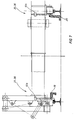
- a rail head 26 subject to wear is first machined on its running surface 27 and a corrugated surface 28 results in the region of the running surface 27. If the rail head 26 is used as an outer rail, then the left-hand running edge 33 is deformed, as shown in FIG. 1, causing deformation a removal profile 30 results, which is shown with dash-dotted lines. This means that the entire profile in the area of line 39 is traversed and a concave removal profile 30 results.
- the deformed actual width between mutually opposite rail heads 26 is measured in that in the area of the undeformed running edge 33, namely at the level of the reference plane 34, a contact or non-contact measurement is carried out between the mutually opposite running edges 33. This ensures that the deformed driving edge is measured at the level of the reference plane and the distance between deformed driving edges at the level of the reference level is set as a measure for the setting of the wheel of the chassis on the roller side.
- the undercarriage according to the invention essentially consists of a main frame 1, which consists of a longitudinal beam 40 to which the crossbeams are fastened parallel to one another at a mutual distance.
- These cross bars 41 form between them a receptacle for a pull-out trolley 3, which essentially consists of a slide which is designed to be displaceable in the transverse direction with corresponding guide rollers in the profile between the cross bars 41.
- a lifting cylinder 6 is arranged in the pull-out undercarriage 3 and is directed downward in the direction of the track bed.
- the entire undercarriage By acting on the lifting cylinder 6, the entire undercarriage can thus be lifted out of the rail bed; it is then rotated around the lifting cylinder 6 and inserted back into the rail bed in the rotated position.
- the longitudinal beam 40 is connected on both sides to an upper and a lower pivot bearing 4, these pivot bearings 4 being part of a main bogie 2.
- This main bogie 2 is formed from two subframes 35, 36 which are at a mutual distance from one another, the upper pivot bearing being designated 4a and the lower pivot bearing 4b.
- a telescopic tube is held, which is part of the main bogie and in which an extension trolley 3 is telescopically guided.
- brackets 42 are firmly welded to the larger tube of the main bogie 2 and carry on their underside main support rollers 8 which, according to FIGS. 5 and 6, roll on the running surface 27 of the rail head 26.
- These main support rollers 8 thus have essentially horizontal axes of rotation.
- lateral guide rollers 7 Perpendicular to these main support rollers 8 are lateral guide rollers 7 with vertical axes of rotation on the underside of the main bogie 2, the guide rollers 7 in a bearing 7a on the Bottom of the main bogie 2 are held. It is important that these guide rollers 7 have a trapezoidal profile on the outer circumference, which is relatively narrow, so that only the deformed driving edges 33 are touched at the level of the reference plane 34. A precisely defined, lateral contact of the entire main bogie 2 on the subframe side 35, 36 for this chassis is thus achieved.
- track sensors 12b act on the same running edge 33 at the level of the reference plane 34 and are pressed by spring force against the deformed driving edge 33 at the level of the reference plane 34 of the rail head 26.
- the precisely defined contact of the guide rollers 7 on the deformed driving edges 33 at the level of the reference plane 34 thus ensures a precisely defined contact of the track sensors 12b on this surface.
- the two subframe arrangements 35, 36 are formed exactly on one side of the undercarriage, so that it is sufficient to describe only one subframe.
- the opposite side of the subframe is also symmetrical and consists of two identically constructed roller assemblies 37, 38, with each roller assembly 37, 38 being assigned two rollers 9 in the exemplary embodiment shown.
- two rollers are through a roller lever 13 connected to each other and rotatably supported on this roller lever.
- a pivot bearing 43 for attacking a lifting device, which essentially consists of a pivot frame 44, which consists of triangular converging beams, which are combined in the lower pivot bearing 43.
- the upper part of the swivel frame 44 is held in a swivel bearing 45 on which one end of a rocker arm 46 engages, the other end of which is held in a rocker bearing 47 fixed to the chassis.
- a first bearing eye 48 is provided for engaging one end of a height compensation cylinder 17, which engages with the other end in the region of the pivot bearing 45 on the pivot frame 44.
- rollers 9 are rotatably mounted on the roller lever 13.
- a steering pin 49 is fixedly connected to the roller lever 13 and engages in a slot-shaped recess 50 of a fork 51 which is pivotally received in a pivot bearing 52.
- the steering pin 49 is fixed in the region of a handlebar 14 arranged, which in turn is firmly connected to the roller lever 13.
- This pivot bearing 52 is fixed to the chassis on the side of the chassis.
- the fork 51 is connected in a rotationally fixed manner to a track control lever 14, on the free, pivotable end of which one side of a track adjustment cylinder 16 engages, the other side of which is received in a bearing eye 53 fixed to the chassis.
- the impeller 9 is thus pivoted in the arrow directions 54 to the rail head of the rail 18, so that the actual width between the two opposite rails 18 in the region of the deformed running edge 33 is set precisely at the level of the reference plane 34.
- track sensors 12 are also pressed onto this rail 18 (left side in FIG. 6) under spring force in order to carry out the desired measurement.
- the track sensors 12 are in turn - as described above - pivotally held on the underside of the chassis and are pressed under spring force against the driving edge 33 at the level of the reference plane of the rail 18.
- the measured dimension is entered into a controller and this controller controls the tracking cylinder 16 so that the rollers 9 of the roller assembly 37, 38 of the main frame 1 are set exactly to this dimension.
- wheel links 19, 20 are anchored in the rail bed in a known manner. It is therefore not possible to measure the distance between the track sensors 12.
- Wheel control sensors 10 are provided (see FIGS. 2 and 3), which, according to FIG. 7, rest on the respective inner sides of the wheel control arms 19, 20. If such a presence of a wheel control arm is detected by the wheel control arm sensors 10a, 10b, then the previously made settings of the track width and the height of the roller arrangement are frozen and locked.
- the rail processing machines are arranged in different locations on the running gear. It was mentioned only by way of example beforehand that the corresponding driver's cab and the supply units are arranged on the unit frame 5.
- the grinding machines 21 for processing the driving edges 33 are fastened to the front of the main bogie 2 and the corresponding grinding wheel processes the vertical driving edges 33.
- a further grinding machine arrangement 22 is preferably arranged in the center area on the longitudinal beam 40 for de-stripping the corrugated surface 28, while in the rear area of the undercarriage a processing machine, e.g. a grinding machine 23 is provided for profile regeneration of the driving edges and the treads. All grinding machines 21-23 are equipped with corresponding grinding wheels 24, only a few of which are shown as examples.
- grinding wheel should also not be understood as limiting. Any machining tools that do not necessarily have the shape of a grinding wheel can be present. Likewise, different milling cutters can be used, and instead of the grinding machines 21-33 shown here, other tools for rail machining can also be carried, such as welding machines or measuring devices, which only the actual state of the deformed and / or undeformed track profile without having to edit it yourself.
Abstract
Description
Die Erfindung betrifft ein Verfahren nach dem Oberbegriff des Patentanspruchs 1, sowie ein Fahrwerk, welches dieses Verfahren verwendet.The invention relates to a method according to the preamble of
Anwendungsgebiet der Erfindung sind Fahrwerke zur Schienenbearbeitung von Schienen allgemeiner Art, insbesondere jedoch von Eisenbahnschienen. Unter den Anwendungsbereich der vorliegenden Erfindung fallen also sowohl Vignolschienen als auch Rillenschienen, z.B. für Strassenbahnen und dergleichen.Field of application of the invention are trolleys for machining rails of rails of a general nature, but in particular of railroad tracks. Both Vignol rails and grooved rails, e.g. for trams and the like.
Mit zunehmender Beanspruchung derartiger Schienen unterliegen diese Schienen einem gewissen Verschleiss, der aus Sicherheits- und Komfortgründen beseitigt werden muß. Hierzu ist es bekannt, Gleisbearbeitungsmaschinen zu verwenden, die im wesentlichen Schleifmaschinen beinhalten, die bestimmte Flächen des durch Verschleiß verformten Schienenkopfes bearbeiten. So ist es z.B. bekannt, die mit Riffelungen versehenen Laufflächen des Schienenkopfes durch entsprechend horizontal arbeitende Schleifmaschinen zu bearbeiten, währenddessen die an den vertikal liegenden Fahrkanten entstehenden Verschleißerscheinungen durch entsprechend vertikal arbeitende Schleifmaschinen bearbeitet werden.With increasing use of such rails, these rails are subject to a certain amount of wear and tear, which must be eliminated for safety and comfort reasons. For this purpose it is known to use track processing machines which essentially contain grinding machines which process certain surfaces of the rail head deformed by wear. So it is e.g. Known to process the treads of the rail head with corrugations by correspondingly horizontally working grinding machines, during which the wear on the vertically lying edges is processed by correspondingly vertically working grinding machines.
Bei den bisher bekannten Gleisbearbeitungsmaschinen besteht jedoch der Nachteil, daß zwar eine Messung des aktuellen Schienenprofils möglich ist, welches die verschiedenen Verschleißkanten aufweist und welches demzufolge verformt ist, daß es aber bisher nicht möglich war, das verformte und dem Verschleiß unterworfene Schienenprofil festzustellen und für die spätere Schienenbearbeitung als Ausgangsbasis heranzuziehen, um das Schienenprofil neu zu definieren, wobei offenbleiben kann, ob möglichst der ursprüngliche, unverformte Zustand angenähert werden soll oder ob ein neues Schienenprofil definiert werden soll. Beide Möglichkeiten werden von der Erfindung umfasst.In the previously known track processing machines, however, there is the disadvantage that it is possible to measure the current rail profile which has the different wear edges and which is consequently deformed, but that it has not previously been possible to determine the deformed and subject to wear rail profile and to use it as a starting point for later rail processing in order to redefine the rail profile, whereby it can remain open whether the original, undeformed state should be approximated if possible or whether a new rail profile should be defined. Both possibilities are covered by the invention.
Daher litten die bekannten Schienenbearbeitungsmaschinen unter dem Nachteil, daß sie nur den verformten Zustand der Schiene als Ausgangsbasis für die weitere Bearbeitung der Schiene namen, ohne die durch Abtrag veränderte Spurweite zu berücksichtigen, was mit schwerwiegenden Nachteilen verbunden ist. Damit fehlt die Bezugsbasis, um das neue, von den Schleifmaschinen hergestellte Profil in den Schienenkopf zu schleifen. Die Schleifbearbeitungen des Schienenkopfes waren daher mehr oder minder zufällig von der gerade aktuellen Spurweite der abgefahrenen Schienenprofile des Doppelstranges abhängig.Therefore, the known rail processing machines suffered from the disadvantage that they only name the deformed condition of the rail as the starting point for further machining of the rail, without taking into account the track gauge changed by abrasion, which is associated with serious disadvantages. This means that there is no reference base for grinding the new profile manufactured by the grinding machines into the rail head. The grinding operations on the rail head were therefore more or less randomly dependent on the current track width of the worn rail profiles of the double strand.
Bei entsprechend abgefahrenen Schienenprofilen konnte es dazu führen, daß das Fahrwerk zur Schienenbearbeitung dann seitlich versetzt wurde, und daß dadurch die Schleifmaschinen ebenfalls eine seitliche Versetzung gegenüber der zu bearbeitenden Schiene erfuhren, was mit einem vermehrten oder verminderten - jedoch immer unerwünschten - Abtrag an dem zu bearbeitenden Schienenkopf führte.With appropriately worn rail profiles, it could lead to the fact that the running gear for rail processing was then laterally displaced and that the grinding machines were also displaced laterally relative to the rail to be machined, which with an increased or reduced - but always undesirable - removal of the machining rail head led.
Der Erfindung liegt deshalb die Aufgabe zugrunde, ein Verfahren zur Schienenbearbeitung und ein dazugehörendes Fahrwerk zu schaffen, welches eine hochpräzise Bearbeitung des Schienenkopfes ermöglicht.The invention is therefore based on the object of providing a method for machining rails and an associated undercarriage which enables high-precision machining of the rail head.
Zur Lösung der gestellten Aufgabe ist das Verfahren durch die technische Lehre des Anspruchs 1 gekennzeichnet.To achieve the object, the method is characterized by the technical teaching of
Wesentliches Merkmal des Verfahrens ist, daß eine Messung der verformten Ist-Weite des Gleisprofils dadurch stattfindet, daß die beiden einander gegenüberliegenden und verformten Fahrkanten auf der Höhe der Bezugsebene des Schienenprofils in ihrem gegenseitigen Abstand erfasst werden. "Bezugsebene" ist eine horizontale Ebene, die in einem bestimmten vertikalen Abstand unterhalb der Lauffläche des Schienenkopfs definiert ist. Der vertikale Abstand von der Lauffläche beträgt z.B. 14 mm. Die dadurch definierte Bezugsebene kann demzufolge in Abhängigkeit von der Höhe des Schienenkopfes im Bereich der verformten oder unverformten Fahrkante liegen.An essential feature of the method is that a measurement of the deformed actual width of the track profile takes place in that the two mutually opposite and deformed moving edges at the height of the reference plane of the rail profile detect their mutual distance will. "Reference plane" is a horizontal plane that is defined at a certain vertical distance below the tread of the rail head. The vertical distance from the tread is 14 mm, for example. The reference plane defined in this way can therefore lie in the region of the deformed or undeformed running edge depending on the height of the rail head.
Wichtig ist also, daß man zunächst das verformte Gleisprofil (das ist die veränderte Spurweite) dadurch feststellt, daß man eine Messung zwischen den einander gegenüberliegenden, verformten Fahrkanten auf Höhe der Bezugsebene vornimmt. Bekannterweise wird der Schienenkopf nur in einem bestimmten Bereich abgefahren, wobei die Abtragung im Bereich der seitlichen Fahrkanten in der oberen Hälfte dieses Schienenkopfes stattfindet.It is therefore important that you first determine the deformed track profile (this is the changed track width) by taking a measurement between the opposing, deformed running edges at the level of the reference plane. As is known, the rail head is traversed only in a certain area, the removal taking place in the area of the lateral running edges in the upper half of this rail head.
Wenn man nun auf diese Weise den Abstand zwischen den verformten Fahrkanten auf Höhe der Bezugsebene der beiden gegenüberliegenden Schienen feststellt, dann hat man die IST-Spurweite des Gleisprofils im verformten Zustand festgestellt. Diese Ist-Spurweite des verformten Gleisprofils ist nun die Ausgangsbasis für das Fahrwerk zur Schienenbearbeitung. Damit wird eine absolut gleichbleibende Ausgangsbasis geschaffen und die Schleifbearbeitungswerkzeuge können ausgehend von diesem "Idealzustand" des verformten Schienenprofils ein neues Profil am Schienenkopf schleifen. Damit wird die durch Abtrag veränderte Spurweite des Gleises an dieser Stelle, wo der Schienenkopf der einen Schiene bearbeitet wird, nicht mehr berücksichtigt. Nachdem erfindungsgemäß die Laufrollen-Anordnung auf der einen Seite der Vorrichtung die Ist-Spurweite des verformten Gleisprofils ausgleicht, erreicht man dadurch bei veränderlicher Ist-Spurweite eine genaue Bezugsbasis zur Bearbeitung des Schienenprofils an der gegenüberliegenden Seite. Alle bekannten Verfahren berücksichtigen die Ist-Spurweite nicht und haben deshalb keine Bezugsbasis für die Bearbeitung des Schienenkopfes.If you determine in this way the distance between the deformed running edges at the level of the reference plane of the two opposite rails, then you have determined the actual track width of the track profile in the deformed state. This actual track gauge of the deformed track profile is now the starting point for the running gear for machining the rails. This creates an absolutely constant starting point and the grinding machining tools can grind a new profile on the rail head based on this "ideal state" of the deformed rail profile. This means that the track gauge of the track, which has changed due to the removal, is no longer taken into account at this point, where the rail head of one rail is being machined. After the roller arrangement on one side of the device compensates for the actual track width of the deformed track profile according to the invention, a precise reference basis for machining the rail profile on the opposite side is thereby achieved with a variable actual track width. All known methods do not take the actual track gauge into account and therefore have no reference base for machining the rail head.
Bei einem weiteren Merkmal des Verfahrensanspruches wird es hierbei bevorzugt, wenn die Abtastung der verformten Fahrkanten auf der vorgeschriebenen Höhe der beiden einander gegenüberliegenden Schienenprofile durch berührende Messgeräte erfolgt.In a further feature of the method claim, it is preferred in this case if the deformed travel edges are scanned at the prescribed height of the two mutually opposite rail profiles by touching measuring devices.
In einer anderen Ausführungsform der Erfindung kann vorgesehen sein, daß die Abtastung und somit die Messung der Ist-Weite durch berührungslose Meßgeräte stattfindet.In another embodiment of the invention it can be provided that the scanning and thus the measurement of the actual width takes place by means of non-contact measuring devices.
Derartige berührungslose Meßgeräte sind z.B. Lasermeßgeräte, Infrarot-Meßgeräte oder dergleichen. Vom Erfindungsgedanken der vorliegenden Erfindung werden also sowohl die Fahrkanten berührende Meßgeräte als auch berührungslose Meßgeräte erfasst.Such non-contact measuring devices are e.g. Laser measuring devices, infrared measuring devices or the like. The inventive idea of the present invention thus covers both measuring devices that touch the driving edges and non-contact measuring devices.
In einer bevorzugten Ausgestaltung des Vorrichtungsanspruchs wird ein Fahrwerk geschaffen, welches im wesentlichen aus einem Führungsfahrwerk und aus einer Laufrollenseite besteht. Das Führungsfahrwerk dieses Fahrwerkes besteht aus zwei einen gegenseitigen Abstand zueinander einnehmenden Fahrschemeln, die auf der einen Schienenseite abrollen, während diesen Fahrschemeln des Führungsfahrwerkes die Laufrollenanordnungen zugeordnet sind, die auf der gegenüberliegenden Schiene abrollen.In a preferred embodiment of the device claim, a chassis is created which essentially consists of a guide chassis and a roller side. The guide carriage of this carriage consists of two mutually spaced subframes that roll on one rail side, while these subframes of the guide carriage are assigned the roller assemblies that roll on the opposite rail.
Jedem Fahrschemel des Führungsfahrwerkes ist also eine Laufrollenanordnung auf der gegenüberliegenden Seite (Laufrollenseite) des Fahrwerkes zugeordnet. Die genannten Fahrschemel auf der einen Seite und die Laufrollen-Anordnungen auf der anderen Seite sind durch ein Fahrwerk miteinander verbunden, welches in einer bevorzugten Ausgestaltung als Auszugfahrwerk ausgebildet ist, um das gesamte Fahrwerk verschiedenen Spurweiten anzupassen. In den meisten Ländern Europas werden bei Staatsbahnen beispielsweise Spurweiten von 1.435 mm verwendet und das Auszugfahrwerk ist dann starr auf diese Spurweite eingestellt. In anderen Staaten und bei Privatbahnen werden andere Spurweiten verwendet und dementsprechend wird die Spurweite des Auszugfahrwerkes darauf eingestellt.Each subframe of the guide undercarriage is therefore assigned a roller arrangement on the opposite side (roller side) of the undercarriage. The above-mentioned subframes on one side and the roller arrangement on the other side are connected to one another by a chassis, which in a preferred embodiment is designed as a pull-out chassis in order to adapt the entire chassis to different track gauges. In most European countries, gauges of 1,435 mm are used for state railways, for example, and the pull-out undercarriage is then rigidly set to this gauge. In other states and with private railways, other track gauges are used and accordingly the track width of the pull-out undercarriage is on it set.
Erfindungswesentlich ist nun, daß auf der Fahrschemelseite des Fahrwerkes seitliche Führungsrollen vorhanden sind, die auf Höhe der Bezugsebene der verformten Fahrkanten anliegen und somit eine genau definierte Position des Fahrwerkes an diesem Schienenprofil gewährleisten.It is essential to the invention that lateral guide rollers are present on the subframe side of the undercarriage, which rest at the level of the reference plane of the deformed traveling edges and thus ensure a precisely defined position of the undercarriage on this rail profile.
Wie vorhin ausgeführt, liegen an den verformten Fahrkanten auch berührende Entfernungsmeßgeräte an, welche die Entfernung zu der gegenüberliegenden, verformten Fahrkante messen. Entsprechend diesem Meßergebnis wird nun die Spurweite des Fahrwerkes hochpräzise eingestellt, indem auf der Laufrollenseite die dort angeordneten Laufrollen in ihrer Spurweite einstellbar und feststellbar ausgebildet sind. Das bedeutet, entsprechend der aktuell gemessenen, verformten Ist-Weite wird nun entsprechen dieser Ist-Weite die Spurweite der Laufrollen auf der Laufrollenseite des Fahrwerkes eingestellt, so daß das Fahrwerk insgesamt nun eine Spurweite aufweist, die genau der verformten Ist-Weite entspricht.
Die Verstellung der Laufrollen an der Laufrollenseite kann über verschiedene Verstellmechanismen erfolgen. Alle Verstellvorrichtungen werden vom Erfindungsgedanken der vorliegenden Erfindung umfasst.As stated above, there are also touching distance measuring devices on the deformed driving edges, which measure the distance to the opposite, deformed driving edge. According to this measurement result, the track width of the undercarriage is now set with high precision by the track widths of the track rollers arranged there being adjustable and lockable. This means that, according to the currently measured, deformed actual width, this actual width is now adjusted to the track width of the rollers on the roller side of the undercarriage, so that the undercarriage now has an overall track width that corresponds exactly to the deformed actual width.
The rollers on the roller side can be adjusted using various adjustment mechanisms. All adjustment devices are encompassed by the inventive concept of the present invention.
In einer ersten Ausführungsform ist vorgesehen, daß die Laufrollenseite des Fahrwerkes jeweils aus einer oder mehreren im Abstand zueinander angeordneten Laufrollen ausgebildet ist, wobei im Falle des Vorhandenseins von mehr als zwei Laufrollen diese Laufrollen durch einen gemeinsamen Balken miteinander verbunden sind, auf dem diese Laufrollen drehbar gelagert sind. Am Balken greift das freie, schwenkbare Ende eines Spurlenkhebels an, der über einen Spureinstellzylinder verschwenkbar ausgebildet ist. Es handelt sich also bei der ersten bevorzugten Ausführungsform um eine pendelnde Aufhängung von bevorzugt Laufrollenpaaren, die an einem die Laufrollen verbindenden Balken angeordnet sind, wobei der Balken - wie dargestellt - pendelnd am unteren freien Ende des Spurlenkhebels angeordnet ist.In a first embodiment it is provided that the roller side of the undercarriage is formed in each case from one or more rollers arranged at a distance from one another, wherein in the presence of more than two rollers these rollers are connected to one another by a common bar on which these rollers are rotatable are stored. The free, pivotable end of a track control lever, which is designed to be pivotable via a track adjustment cylinder, engages on the beam. The first preferred embodiment is therefore an oscillating suspension of preferably pairs of rollers, which are arranged on a beam connecting the rollers, the beam - as shown - oscillating on lower free end of the track control lever is arranged.
In einer weiteren Ausführungsform der vorliegenden Erfindung ist vorgesehen, daß die Laufrollen bzw. Laufrollenpaare verschiebbar in Art einer Längsführung im Fahrgestell gehalten sind, und diese Längsführung durch entsprechende Linearantriebs-Einheiten verschiebbar ausgebildet ist. Hierbei sind dann die ein oder mehreren Laufrollen in einem Schlitten gelagert, der verschiebbar im Fahrgestell des Fahrwerkes aufgenommen ist.In a further embodiment of the present invention it is provided that the rollers or pairs of rollers are slidably held in the manner of a longitudinal guide in the chassis, and this longitudinal guide is designed to be displaceable by corresponding linear drive units. In this case, the one or more rollers are then mounted in a carriage which is slidably received in the chassis of the chassis.
In einer Weiterbildung der vorliegenden Erfindung ist vorgesehen, daß das Fahrwerk eine stabile Dreipunktauflage dadurch bildet, daß die Laufrollen-Anordnungen höheneinstellbar am Fahrwerk gehalten sind. Diese Höheneinstellung gewährleistet, daß eine Dreipunktauflage erreicht wird, weil die Fahrschemel auf der einen Schienenseite starr miteinander verbunden sind, während die Laufrollenanordnungen auf der gegenüberliegenden Schienenseite höheneinstellbar ausgebildet sind, um zu gewährleisten, daß jeweils nur drei "Punkte" auf den beiden Schienen belastet werden. Dadurch wird gesorgt, daß eine kraftresultierende in der Mitte des Fahrwerkes zwischen den beiden Laufrollenanordnungen erzeugt wird, was die vorher erwähnte, stabile Dreipunktauflage gewährleistet. Auf der Seite der Laufrollen-Anordnungen wird also ein virtueller Auflagepunkt auf der Schiene im Bereich zwischen den beiden - einen gegenseitigen Abstand voneinander einnehmenden - Laufrollen-Anordnungen erzeugt und diesem virtuellen Auflagepunkt stehen die beiden gegenüberliegenden, stabilen und feststehenden Auflagepunkte im Bereich der Fahrschemel gegenüber.In a further development of the present invention it is provided that the undercarriage forms a stable three-point support in that the track roller arrangements are held on the undercarriage in a height-adjustable manner. This height adjustment ensures that a three-point support is achieved because the subframes are rigidly connected to one another on one side of the rail, while the roller assemblies on the opposite side of the rail are designed to be height-adjustable in order to ensure that only three "points" are loaded on each of the two rails . This ensures that a resultant force is generated in the middle of the chassis between the two roller assemblies, which ensures the aforementioned stable three-point support. On the side of the caster arrangements, a virtual support point on the rail is thus created in the area between the two caster arrangements, which take a mutual distance from one another, and this virtual support point is opposed by the two stable, fixed support points opposite each other in the area of the subframe.
Die Spurweitensensoren liegen dann demzufolge sowohl auf der Fahrschemelseite auf Höhe der Bezugsebene an den verformten Fahrkanten als auch auf der Laufrollenseite ebenfalls auf Höhe der Bezugsebene an den verformten Fahrkanten an, und messen den Ist-Zustand des Gleisprofils im verformten Zustand.The track width sensors are then in contact with the deformed running edges on the subframe side at the level of the reference level and also on the deformed driving edges at the level of the reference level and measure the actual state of the track profile in the deformed state.
Ein weiteres wesentliches Merkmal der Erfindung ist, daß nun erfindungsgemäss mit dem Verfahren und dem Fahrwerk, welches obenstehend beschrieben wurde, es nun erstmals möglich ist, auch Schienenbereiche im Bereich von einfachen Kreuzungen und Weichen sowie im Bereich von doppelten Kreuzungsweichen zu bearbeiten. (Dies war vorher nicht möglich, weil alle bisher bekannten Fahrwerke nur den verformten Ist-Zustand der Fahrbahnkanten erfassten und demzufolge mehr oder minder undefiniert ein neues Schienenprofil anbrachten). Mit der vorliegenden Erfindung ist nun vorgesehen, daß sobald das Fahrwerk in den Bereich von Radlenkern fährt, die nur im Bereich von Weichen gegenüber dem Herzstück angeordnet sind, dann diese Anfahrbewegung auf die dort angeordneten Radlenker von einem Radlenkersensor festgestellt wird, der das Vorhandensein derartiger Radlenkerschienen erfasst und der Steuerung des Fahrwerkes mitteilt, daß nun alle vorher gemessenene Einstellungen festgefroren werden und das Fahrwerk in dieser Stellung verriegelt wird. Nachdem es keine genau definierten Spurweiten im Bereich des Herzstückes von Weichen und Kreuzungen gibt, ist es nun erstmals möglich, auch diesen Bereich - bei "festgefrorenem" Fahrwerk - zu bearbeiten.Another essential feature of the invention is that, according to the invention, with the method and the chassis which have been described above, it is now possible for the first time to machine rail areas in the area of simple crossings and points as well as in the area of double crossing points. (This was not possible before, because all previously known undercarriages only recorded the deformed actual condition of the roadway edges and therefore attached a new rail profile more or less undefined). With the present invention it is now provided that as soon as the undercarriage moves into the area of wheel control arms which are only arranged in the area of switches opposite the centerpiece, this approach movement to the wheel control arms arranged there is determined by a wheel control arm sensor which detects the presence of such wheel control arm rails detected and notifies the control of the undercarriage that all previously measured settings are now frozen and the undercarriage is locked in this position. Since there are no precisely defined track gauges in the area of the heart of switches and crossings, it is now possible for the first time to work on this area too - with a "frozen" undercarriage.
Der Erfindungsgegenstand der vorliegenden Erfindung ergibt sich nicht nur aus dem Gegenstand der einzelnen Patentansprüche, sondern auch aus der Kombination der einzelnen Patentansprüche untereinander. Alle in den Unterlagen - einschließlich der Zusammenfassung - offenbarten Angaben und Merkmale, insbesondere die in den Zeichnungen dargestellte räumliche Ausbildung werden als erfindungswesentlich beansprucht, soweit sie einzeln oder in Kombination gegenüber dem Stand der Technik neu sind.The subject matter of the present invention results not only from the subject matter of the individual patent claims, but also from the combination of the individual patent claims with one another. All information and features disclosed in the documents - including the summary -, in particular the spatial design shown in the drawings, are claimed to be essential to the invention insofar as they are new to the prior art, individually or in combination.
Im folgenden wird die Erfindung anhand von lediglich einen Ausführungsweg darstellende Zeichnungen näher erläutert. Hierbei gehen aus den Zeichnungen und ihrer Beschreibung weitere erfindungswesentliche Merkmale und Vorteile der Erfindung hervor.The invention is explained in more detail below with the aid of drawings which illustrate only one embodiment. Further features and advantages of the invention which are essential to the invention emerge from the drawings and their description.
Es zeigen:
- Figur 1:
- schematisiert in Stirnansicht einen Schienenkopf in verformtem und nicht verformtem Zustand,
- Figur 2:
- Seitenansicht des Fahrwerkes von der Seite des Führungsfahrwerkes her (Pfeilrichtung II in Figur 4).
- Figur 3:
- Seitenansicht des Fahrwerkes von der Laufrollenseite her (Pfeilrichtung III in Figur 4),
- Figur 4:
- Draufsicht auf das Fahrwerk,
- Figur 5:
- Schnitt durch das Fahrwerk in Höhe des Pfeiles V-V in
Figur 4, - Figur 6:
- Schnitt durch das Fahrwerk in Höhe des Pfeiles VI-VI in
Figur 4, - Figur 7:
- Stirnansicht des Fahrwerkes in Richtung des Pfeiles VII in
Figur 4.
- Figure 1:
- schematically in front view a rail head in the deformed and not deformed state,
- Figure 2:
- Side view of the undercarriage from the side of the guide undercarriage (arrow direction II in FIG. 4).
- Figure 3:
- Side view of the undercarriage from the roller side (arrow direction III in FIG. 4),
- Figure 4:
- Top view of the chassis,
- Figure 5:
- Section through the chassis at the height of arrow VV in Figure 4,
- Figure 6:
- Section through the chassis at the height of arrow VI-VI in Figure 4,
- Figure 7:
- Front view of the undercarriage in the direction of arrow VII in FIG. 4.
Anhand der Figur 1 sollen die wesentlichen Merkmale eines Schienenkopfes 26 erläutert werden.The essential features of a
Ein dem Verschleiß unterworfener Schienenkopf 26 wird zunächst an seiner Lauffläche 27 abgearbeitet und es ergibt sich eine Riffelfläche 28 im Bereich der Lauffläche 27. Ist der Schienenkopf 26 als Außenschiene eingesetzt, dann wird gemäss der Darstellung in Figur 1 die linke Fahrkante 33 verformt, wodurch sich ein Abtragprofil 30 ergibt, welches mit strichpunktierten Linien dargestellt ist. D.h. das gesamte Profil im Bereich der Linie 39 wird abgefahren und es ergibt sich ein konkaves Abtragprofil 30.A
Wichtig ist nun, daß das Laufrad 25 eines Eisenbahnwagens oder eines anderen Gleisfahrzeuges sich nun mit seinem Spurkranz 31 in dieses Abtragprofil 30 hineinbewegt und eine seitliche Versetzung erfährt, wie dies mit strichpunktierten Linien in der Figur 1 dargestellt ist.It is now important that the
Ebenso ist es möglich, daß ein Laufrad 25' eine entgegengesetzte, seitliche Versetzung erfährt, wobei deren Spurkranz 31 dann außerhalbdes Bereichs des Abtragprofils 30 gelangt.It is also possible for an impeller 25 'to experience an opposite, lateral displacement, the
Die Rollfläche 32 beider Laufräder 25,25' wälzt sich dann auf der Riffelfläche 28 ab.The rolling
Ebenso ist es möglich, daß der Schienenkopf 26 noch seitliche Auswalzungen 29 erfährt, die durch gestrichelte Linien in Figur 1 dargestellt sind.It is also possible that the
Wichtig ist nun, daß die verformte Istweite zwischen einander gegenüberliegenden Schienenköpfen 26 dadurch gemessen wird, daß im Bereich der unverformten Fahrkante 33, nämlich auf Höhe der Bezugsebene 34, eine berührende oder berühungslose Messung zwischen den einander gegenüberliegenden Fahrkanten 33 vorgenommen wird. Damit wird gewährleistet, daß die verformte Fahrkante auf Höhe der Bezugsebene gemessen wird und der Abstand zwischen verformten Fahrkanten auf Höhe der Bezugsebene als Maß für die Einstellung des Laufrades des Fahrwerks an der Laufrollenseite eingestellt wird.It is now important that the deformed actual width between mutually opposite rail heads 26 is measured in that in the area of the undeformed running
Das Fahrwerk nach der Erfindung besteht im wesentlichen aus einem Hauptrahmen 1, der aus einem Längsbalken 40 besteht, an dem die Querbalken in gegenseitigem Abstand parallel zueinander befestigt sind. Diese Querbalken 41 bilden zwischen sich eine Aufnahme für ein Auszugfahrwerk 3, welches im wesentlichen aus einem Schlitten besteht, der mit entsprechenden Führungsrollen im Profil zwischen den Querbalken 41 in Querrichtung verschiebbar ausgebildet ist.The undercarriage according to the invention essentially consists of a
Im Auszugfahrwerk 3 ist ein Hubzylinder 6 angeordnet, der nach unten in Richtung auf das Gleisbett gerichtet ist.A
Durch Beaufschlagung des Hubzylinders 6 kann somit das gesamte Fahrwerk aus dem Schienenbett herausgehoben werden; es wird dann um den Hubzylinder 6 herum gedreht und in gedrehter Stellung wieder in das Schienenbett eingesetzt.By acting on the
Der Längsbalken 40 ist an seinen beiden Seiten mit einem oberen und einem unteren Drehlager 4 verbunden, wobei diese Drehlager 4 Teil jeweils eines Hauptdrehgestells 2 sind.The
Dieses Hauptdrehgestell 2 wird gebildet aus zwei einen gegenseitigen Abstand zueinander einnehmenden Fahrschemeln 35,36, wobei das obere Drehlager mit 4a und das untere Drehlager mit 4b bezeichnet ist.This
In diesem Drehlager ist ein Teleskoprohr gehalten, welches Teil des Hauptdrehgestells ist und in welchem ein Auszugfahrwerk 3 teleskopierbar geführt ist.In this pivot bearing, a telescopic tube is held, which is part of the main bogie and in which an
Mit dieser Anordnung ist es möglich, die Spurweite zwischen der einen Schienenseite und der anderen Schienenseite einzustellen.With this arrangement, it is possible to set the track width between one side of the rail and the other side of the rail.
An der Seite der Fahrschemel 35,36 sind Konsolen 42 fest mit dem größeren Rohr des Hauptdrehgestells 2 verschweisst und tragen an ihrer Unterseite Hauptstützrollen 8, welche gemäss den Figuren 5 und 6 auf der Lauffläche 27 des Schienenkopfes 26 abrollen.On the side of the
Diese Hauptstützrollen 8 haben also im wesentlichen horizontale Drehachsen.These
Senkrecht zu diesen Hauptstützrollen 8 sind seitliche Führungsrollen 7 mit vertikalen Drehachsen an der Unterseite des Hauptdrehgestells 2 angeordnet, wobei die Führungsrollen 7 in einem Lager 7a an der Unterseite des Hauptdrehgestells 2 gehalten sind. Wichtig ist, daß diese Führungsrollen 7 ein Trapezprofil am Außenumfang aufweisen, welches relativ schmal ist, so daß nur die verformten Fahrkanten 33 auf Höhe der Bezugsebene 34 berührt werden. Damit wird eine genau definierte, seitliche Anlage des gesamten Hauptdrehgestells 2 auf der Fahrschemelseite 35,36 für dieses Fahrgestell erreicht.Perpendicular to these
Es wird noch hinzugefügt, daß auf dem vorher erwähnten Aggregatrahmen 5, der zwischen den Querbalken 41 verschiebbar geführt ist, sämtliche Maschinen zur Energieversorgung sowie der Führerstand des Fahrzeugs angebracht sind.It is also added that on the
Ferner ist wesentlich, daß gemäss Figur 6 an der gleichen Fahrkante 33 auf Höhe der Bezugsebene 34 Spursensoren 12b angreifen, welche durch Federkraft an die verformte Fahrkante 33 auf Höhe der Bezugsebene 34 des Schienenkopfes 26 angepresst werden.It is also essential that, according to FIG. 6,
Durch die genau definierte Anlage der Führungsrollen 7 an den verformten Fahrkanten 33 auf Höhe der Bezugsebene 34 wird somit eine genau definierte Anlage der Spursensoren 12b an dieser Fläche gewährleistet.The precisely defined contact of the
Die beiden Fahrschemelanordnungen 35,36 sind genau identsich auf der einen Seite des Fahrwerks ausgebildet, so daß es ausreicht, lediglich einen einzigen Fahrschemel zu beschreiben.The two
Die gegenüberliegende Seite des Fahrschemels ist ebenso symmetrisch ausgebildet und besteht aus zwei gleichartig aufgebauten Laufrollenanordnungen 37,38, wobei im gezeigten Ausführungsbeispiel jeder Laufrollenanordnung 37,38 jeweils zwei Laufrollen 9 zugeordnet sind.The opposite side of the subframe is also symmetrical and consists of two identically constructed
Es wurde vorstehend schon darauf hingewiesen, daß auch mehr als zwei Laufrollen verwendet werden können.It has already been pointed out above that more than two rollers can also be used.
Im gezeigten Ausführungsbeispiel sind jeweils zwei Laufrollen durch einen Laufrollenhebel 13 miteinander verbunden und jeweils auf diesem Laufrollenhebel drehbar gelagert. In der Mitte des Laufrollenhebels 13 ist ein Schwenklager 43 für den Angriff einer Hubeinrichtung, die im wesentlichen aus einem Schwenkrahmen 44 besteht, der aus dreiecksförmig zusammenlaufenden Balken besteht, die im unteren Schwenklager 43 vereinigt sind. Der obere Teil des Schwenkrahmens 44 ist in einem Schwenklager 45 gehalten, an dem das eine Ende eines Wippenhebels 46 angreift, der mit seinem anderen Ende in einem fahrwerkfesten Wippenlager 47 gehalten ist.
An der Fahrwerkseite ist ein erstes Lagerauge 48 für den Angriff des einen Endes eines Höhenausgleichszylinders 17 vorgesehen, der mit seinem anderen Ende im Bereich des Schwenklagers 45 an dem Schwenkrahmen 44 angreift.In the embodiment shown, two rollers are through a
On the chassis side, a
Durch die Betätigung des Höhenausgleichszylinders 17 wird somit die Höhe der Laufrollenanordnung in Bezug zu dem gesamten Hauptrahmen 1 eingestellt.By actuating the
Nachdem diese Höheneinstelleinrichtung an beiden Laufrollenanordnungen 37,38 vorhanden ist, wird somit durch entsprechende Betätigung der beiden Höhenausgleichszylinder ein virtueller Abstützpunkt zwischen den beiden Laufrollenanordnungen 37,38 geschaffen, der etwa in Höhe des Aggregatrahmens 5 liegt, d.h. also im Mittenbereich des Fahrwerks.After this height adjustment device is present on both
Nachstehend wird die Veränderung der Spurweite durch entsprechende Ansteuerung der Laufrollen 8 erläutert.The change in the track width by appropriate control of the
Die Laufrollen 9 sind - wie vorher erwähnt - drehbar auf dem Laufrollenhebel 13 gelagert.As previously mentioned, the
Mit dem Laufrollenhebel 13 ist fest ein Lenkzapfen 49 verbunden, der in eine langlochförmige Ausnehmung 50 einer Gabel 51 eingreift, die schwenkbar in einem Schwenklager 52 aufgenommen ist.
Der Lenkzapfen 49 ist hierbei fest im Bereich eines Lenkers 14 angeordnet, der seinerseits fest mit dem Laufrollenhebel 13 verbunden ist.A
The
Dieses Schwenklager 52 ist fahrwerkfest an der Seite des Fahrwerks angebracht. Die Gabel 51 ist drehfest mit einem Spurlenkhebel 14 verbunden, an dessen freiem, schwenkbaren Ende die eine Seite eines Spureinstellzylinders 16 angreift, der mit seiner anderen Seite in einem fahrwerkfesten Lagerauge 53 aufgenommen ist.This pivot bearing 52 is fixed to the chassis on the side of the chassis. The
Durch die Betätigung des Spureinstellzylinders 16 wird somit das Laufrad 9 in den Pfeilrichtungen 54 zum Schienenkopf der Schiene 18 verschwenkt, so daß damit die Istweite zwischen den beiden gegenüberliegenden Schienen 18 im Bereich der verformten Fahrkante 33 auf Höhe der Bezugsebene 34 präzise eingestellt wird.By actuating the
Wichtig ist, daß auch an dieser Schiene 18 (linke Seite in Figur 6) Spursensoren 12 unter Federkraft angepresst werden, um somit die gewünschte Messung durchzuführen. Die Spursensoren 12 sind an dieser Seite wiederum - wie vorhin beschrieben - schwenkbar an der Unterseite des Fahrgestells gehalten und werden unter Federkraft an die Fahrkante 33 auf Höhe der Bezugsebene der Schiene 18 angepresst.It is important that
Entsprechend dem tatsächlich gemessenen Abstand zwischen den beiden Spursensoren 12 wird das gemessene Maß in eine Steuerung eingegeben und diese Steuerung steuert den Spureinstellzylinder 16 an, so daß die Laufrollen 9 der Laufrollenanordnung 37,38 des Hauptrahmens 1 genau auf dieses Maß eingestellt werden.According to the actually measured distance between the two
Im folgenden wird noch beschrieben, daß Anordnungen vorhanden sind, die das Einfahren des gesamten Fahrwerks in einen Gleisbereich feststellen. Im Gleisbereich sind gegenüberliegend zum Herzstück in bekannter Weise Radlenker 19,20 im Schienenbett verankert. Es kann daher keine Abstandsmessung zwischen den Spursensoren 12 vorgenommen werden. Um das Einfahren in einen derartigen Weichenbereich zu erfassen, sind Radlenkersensoren 10 vorgesehen (vergl. Figur 2 und 3), die sich gemäss Figur 7 an die jeweiligen Innenseiten der Radlenker 19,20 anlegen. Wird ein derartiges Vorhandensein eines Radlenkers durch die Radlenkersensoren 10a, 10b erfasst, dann werden sofort die vorher getroffenen Einstellungen der Spurweite und der Höhenlage der Laufrollenanordnungen eingefroren und arretiert.In the following it will be described that there are arrangements that determine the retraction of the entire undercarriage in a track area. In the track area opposite to the centerpiece, wheel links 19, 20 are anchored in the rail bed in a known manner. It is therefore not possible to measure the distance between the
Damit ist es nun erstmals möglich, auch in diesen Schienenbereichen, in denen keine Abstandsmessung zur Feststellung der Spurweite stattfinden kann, eine Bearbeitung der Schienen durchzuführen.It is now possible for the first time to carry out machining of the rails even in those rail areas in which no distance measurement can be carried out to determine the track gauge.
Allgemein wird darauf hingewiesen, daß die Schienenbearbeitungsmaschinen an verschiedenen Stellen verteilt auf dem Fahrwerk angeordnet sind. Nur beispielhaft wurde vorher erwähnt, daß der entsprechende Führerstand und die Versorgungsaggregate auf dem Aggregatrahmen 5 angeordnet sind. Die Schleifmaschinen 21 zur Bearbeitung der Fahrkanten 33 sind hingegen an der Vorderseite des Hauptdrehgestells 2 befestigt und die entsprechende Schleifscheibe bearbeitet die vertikalen Fahrkanten 33.It is generally pointed out that the rail processing machines are arranged in different locations on the running gear. It was mentioned only by way of example beforehand that the corresponding driver's cab and the supply units are arranged on the
Zur Entriffelung der Riffelfläche 28 ist bevorzugt eine weitere Schleifmaschinenanordnung 22 im Mittenbereich am Längsbalken 40 angeordnet, während im hinteren Bereich des Fahrwerks eine Bearbeitungsmaschine, z.B. eine Schleifmaschine 23 zur Profil-Regenerierung der Fahrkanten und der Laufflächen vorgesehen ist. Alle Schleifmaschinen 21-23 sind mit entsprechenden Schleifscheiben 24 ausgerüstet, von denen nur einige beispielhaft dargestellt sind.A further grinding
Der Begriff "Schleifscheibe" soll auch nicht beschränkend verstanden werden. Es können beliebige spanabhebende Bearbeitungswerkzeuge vorhanden sein, die nicht notwendigerweise die Formgebung einer Schleifscheibe aufweisen. Ebenso können verschiedene Fräser verwendet werden, und statt der hier gezeigten Schleifmaschinen 21-33 können auch andere Werkzeuge zur Schienenbearbeitung mitgeführt werden, wie z.B. Schweißmaschinen oder Meßgeräte, die nur den Ist-Zustand des verformten und/oder unverformten Gleisprofils vermessen, ohne selbst eine Bearbeitung daran vorzunehmen.
Claims (9)
Applications Claiming Priority (2)
| Application Number | Priority Date | Filing Date | Title |
|---|---|---|---|
| DE4200945 | 1992-01-16 | ||
| DE19924200945 DE4200945A1 (en) | 1992-01-16 | 1992-01-16 | METHOD FOR MEASURING A RAIL AND TRACK PROFILE AND CHASSIS FOR MACHINING |
Publications (1)
| Publication Number | Publication Date |
|---|---|
| EP0552473A1 true EP0552473A1 (en) | 1993-07-28 |
Family
ID=6449600
Family Applications (1)
| Application Number | Title | Priority Date | Filing Date |
|---|---|---|---|
| EP92121532A Withdrawn EP0552473A1 (en) | 1992-01-16 | 1992-12-18 | Method of measuring the profile of a rail and track and moving gear for the processing of rails |
Country Status (2)
| Country | Link |
|---|---|
| EP (1) | EP0552473A1 (en) |
| DE (1) | DE4200945A1 (en) |
Cited By (7)
| Publication number | Priority date | Publication date | Assignee | Title |
|---|---|---|---|---|
| AT5911U3 (en) * | 2002-10-29 | 2003-11-25 | Plasser Bahnbaumasch Franz | METHOD FOR CONTACT-FREE MEASUREMENT OF A CROSS-PROFILE OR DISTANCE FROM RAILS OF A TRACK |
| WO2005098352A1 (en) * | 2004-04-06 | 2005-10-20 | Witt Industrie Elektronik Gmbh | Method and device for detecting the condition of and machining switches in track systems |
| WO2012061864A1 (en) * | 2010-11-11 | 2012-05-18 | Linsinger Maschinenbau Gesellschaft M.B.H. | Method for profiling a laid rail and processing vehicle |
| WO2014040094A1 (en) * | 2012-09-12 | 2014-03-20 | Vossloh Mfl Rail Milling Gmbh | Method and device for lateral copying at a rail |
| WO2014040095A3 (en) * | 2012-09-13 | 2014-05-08 | Vossloh Mfl Rail Milling Gmbh | Method and device for force-dependent controlling in the machining of rails |
| EP2808446A1 (en) * | 2013-05-27 | 2014-12-03 | System7-Railsupport GmbH | Device for machining a railway track |
| CN115626195A (en) * | 2022-09-09 | 2023-01-20 | 深圳市埃伯瑞科技有限公司 | Wave mill measuring instrument |
Families Citing this family (4)
| Publication number | Priority date | Publication date | Assignee | Title |
|---|---|---|---|---|
| DE202017106689U1 (en) | 2017-11-06 | 2017-12-06 | Geiger + Schüle Beteiligungs-Gmbh & Co. Kg | Track construction device for machining rails |
| DE102017125839A1 (en) | 2017-11-06 | 2019-05-09 | Geiger + Schüle Beteiligungs-Gmbh & Co. Kg | Track construction device for machining rails |
| CN109353371B (en) * | 2018-12-12 | 2023-11-10 | 湖南高创海捷工程技术有限公司 | Full-automatic steel rail non-contact profile detection device |
| CN111809463B (en) * | 2019-04-11 | 2023-06-16 | 中国铁建高新装备股份有限公司 | Intelligent steel rail polishing system based on AI method and corresponding polishing method |
Citations (6)
| Publication number | Priority date | Publication date | Assignee | Title |
|---|---|---|---|---|
| FR2044326A5 (en) * | 1969-05-16 | 1971-02-19 | Miferma | |
| AT321346B (en) * | 1971-09-14 | 1975-03-25 | British Railways Board | Device on a rail vehicle for detecting parameters, in particular the gauge, of railway tracks by means of non-contact scanners |
| GB2070671A (en) * | 1980-02-27 | 1981-09-09 | Plasser Bahnbaumasch Franz | Device for examining the surface of rail heads |
| EP0044885A1 (en) * | 1980-07-24 | 1982-02-03 | Speno International S.A. | Method and apparatus for determining at least one geometrical characteristic of the rail heads of a railway track |
| EP0114284A2 (en) * | 1982-12-27 | 1984-08-01 | Speno International S.A. | Device for continuously measuring the shape of the transversal profile of the useful part of the head of at least one rail of a railway track |
| DE3444723A1 (en) * | 1984-12-07 | 1986-06-12 | Richard Gehrcke | Device for detecting the track geometry by means of a laser |
Family Cites Families (6)
| Publication number | Priority date | Publication date | Assignee | Title |
|---|---|---|---|---|
| AT368220B (en) * | 1979-08-14 | 1982-09-27 | Plasser Bahnbaumasch Franz | MACHINE FOR MACHINING THE RAIL HEAD SURFACE OF AN INSTALLED TRACK |
| US4785589A (en) * | 1986-02-28 | 1988-11-22 | Les Fils D'auguste Scheuchzer S.A. | Process for measuring and grinding the profile of a rail head |
| DD251730A1 (en) * | 1986-08-01 | 1987-11-25 | Verkehrswesen Hochschule | METHOD AND ARRANGEMENT FOR MEASURING THE ROLLING LINE |
| DE3772057D1 (en) * | 1987-11-07 | 1991-09-12 | Scheuchzer Fils Auguste | GRINDING MACHINE FOR REPROFILING RAIL HEADS. |
| DE3913159A1 (en) * | 1989-04-21 | 1990-10-25 | Linsinger Maschinenbau Gmbh | Measuring wave-shaped rail deformation - using vehicle with two sensors measuring height difference of two rail top points |
| CH680598A5 (en) * | 1989-08-28 | 1992-09-30 | Speno International |
-
1992
- 1992-01-16 DE DE19924200945 patent/DE4200945A1/en not_active Withdrawn
- 1992-12-18 EP EP92121532A patent/EP0552473A1/en not_active Withdrawn
Patent Citations (6)
| Publication number | Priority date | Publication date | Assignee | Title |
|---|---|---|---|---|
| FR2044326A5 (en) * | 1969-05-16 | 1971-02-19 | Miferma | |
| AT321346B (en) * | 1971-09-14 | 1975-03-25 | British Railways Board | Device on a rail vehicle for detecting parameters, in particular the gauge, of railway tracks by means of non-contact scanners |
| GB2070671A (en) * | 1980-02-27 | 1981-09-09 | Plasser Bahnbaumasch Franz | Device for examining the surface of rail heads |
| EP0044885A1 (en) * | 1980-07-24 | 1982-02-03 | Speno International S.A. | Method and apparatus for determining at least one geometrical characteristic of the rail heads of a railway track |
| EP0114284A2 (en) * | 1982-12-27 | 1984-08-01 | Speno International S.A. | Device for continuously measuring the shape of the transversal profile of the useful part of the head of at least one rail of a railway track |
| DE3444723A1 (en) * | 1984-12-07 | 1986-06-12 | Richard Gehrcke | Device for detecting the track geometry by means of a laser |
Cited By (11)
| Publication number | Priority date | Publication date | Assignee | Title |
|---|---|---|---|---|
| AT5911U3 (en) * | 2002-10-29 | 2003-11-25 | Plasser Bahnbaumasch Franz | METHOD FOR CONTACT-FREE MEASUREMENT OF A CROSS-PROFILE OR DISTANCE FROM RAILS OF A TRACK |
| WO2005098352A1 (en) * | 2004-04-06 | 2005-10-20 | Witt Industrie Elektronik Gmbh | Method and device for detecting the condition of and machining switches in track systems |
| WO2012061864A1 (en) * | 2010-11-11 | 2012-05-18 | Linsinger Maschinenbau Gesellschaft M.B.H. | Method for profiling a laid rail and processing vehicle |
| US9416498B2 (en) | 2010-11-11 | 2016-08-16 | Linsinger Maschinenbau Gesellschaft M.B.H. | Method for profiling a laid rail and processing vehicle |
| WO2014040094A1 (en) * | 2012-09-12 | 2014-03-20 | Vossloh Mfl Rail Milling Gmbh | Method and device for lateral copying at a rail |
| CN104603361A (en) * | 2012-09-12 | 2015-05-06 | 福斯罗Mfl钢轨轧机有限责任公司 | Method and device for lateral copying at a rail |
| US20150233064A1 (en) * | 2012-09-12 | 2015-08-20 | Vossloh Mfl Rail Milling Gmbh | Method and device for lateral copying of a rail |
| US9822492B2 (en) | 2012-09-12 | 2017-11-21 | Vossloh Mfl Rail Milling Gmbh | Method and device for lateral copying of a rail |
| WO2014040095A3 (en) * | 2012-09-13 | 2014-05-08 | Vossloh Mfl Rail Milling Gmbh | Method and device for force-dependent controlling in the machining of rails |
| EP2808446A1 (en) * | 2013-05-27 | 2014-12-03 | System7-Railsupport GmbH | Device for machining a railway track |
| CN115626195A (en) * | 2022-09-09 | 2023-01-20 | 深圳市埃伯瑞科技有限公司 | Wave mill measuring instrument |
Also Published As
| Publication number | Publication date |
|---|---|
| DE4200945A1 (en) | 1993-07-22 |
Similar Documents
| Publication | Publication Date | Title |
|---|---|---|
| EP0360950B1 (en) | Continuous-motion (non-stop) track-tamping, levelling and lining machine | |
| DE2612174A1 (en) | RAIL GRINDING MACHINE | |
| DE3222208A1 (en) | DEVICE FOR MILLING RAIL HEADS | |
| EP0752499A1 (en) | Rail loading wagon | |
| EP0682148A1 (en) | Installation for transporting lengths of assembled track | |
| EP2412871A1 (en) | Device for abrasive processing of rails laid in a platform | |
| CH661952A5 (en) | DRIVABLE TRACK CONSTRUCTION MACHINE WITH A TOOL ARRANGEMENT FOR PUTTING, LEVELING AND SIDE-ALIGNING A TRACK. | |
| DD152594A5 (en) | MACHINE FOR MACHINING THE RAILING COPY SURFACE OF A LAYERED TRACK | |
| CH661757A5 (en) | DRIVABLE TRACK CONSTRUCTION MACHINE WITH TWO CONNECTED CHASSIS FRAMES. | |
| EP0552473A1 (en) | Method of measuring the profile of a rail and track and moving gear for the processing of rails | |
| DE3106754A1 (en) | TRACK CONSTRUCTION MACHINE WITH TOOL BRACKET FOR LIFTING AND LEVELING TOOLS | |
| EP0455179B1 (en) | Track tamping machine with in transverse direction of the track displaceable tamping units | |
| CH635151A5 (en) | TRACKABLE MACHINE FOR MACHINING THE RAIL HEAD SURFACES. | |
| DE102007060215A1 (en) | Device for processing a running edge | |
| CH622302A5 (en) | Track-tamping machine, in particular for tamping down track points, crossings and the like | |
| DE1956916C3 (en) | Track pot leveling machine | |
| EP1443149B1 (en) | Track treatment machine | |
| EP0811721A2 (en) | Device for laying railway track | |
| DE202006015507U1 (en) | Machine for grinding railway track has a frame supported on four flanged wheels and with a tilt controlled grinding system | |
| EP0699802B1 (en) | Platelayer wagon for loading and unloading long railway rails | |
| DE2257255A1 (en) | MILLING MACHINE | |
| DD209864A5 (en) | RUNNING MACHINE WITH STOPPING AND STABILIZATION UNIT | |
| DE20319063U1 (en) | Device for supporting bogies on wheelset processing machines | |
| DE3601837C2 (en) | ||
| DE3914830C3 (en) | Track measuring device |
Legal Events
| Date | Code | Title | Description |
|---|---|---|---|
| PUAI | Public reference made under article 153(3) epc to a published international application that has entered the european phase |
Free format text: ORIGINAL CODE: 0009012 |
|
| AK | Designated contracting states |
Kind code of ref document: A1 Designated state(s): AT BE CH DE ES FR GB IT LI LU NL SE |
|
| 17P | Request for examination filed |
Effective date: 19930930 |
|
| STAA | Information on the status of an ep patent application or granted ep patent |
Free format text: STATUS: THE APPLICATION HAS BEEN WITHDRAWN |
|
| 17Q | First examination report despatched |
Effective date: 19941202 |
|
| 18W | Application withdrawn |
Withdrawal date: 19950103 |