EP0444019B1 - Broyeur à mâchoires - Google Patents
Broyeur à mâchoires Download PDFInfo
- Publication number
- EP0444019B1 EP0444019B1 EP91890034A EP91890034A EP0444019B1 EP 0444019 B1 EP0444019 B1 EP 0444019B1 EP 91890034 A EP91890034 A EP 91890034A EP 91890034 A EP91890034 A EP 91890034A EP 0444019 B1 EP0444019 B1 EP 0444019B1
- Authority
- EP
- European Patent Office
- Prior art keywords
- jaw
- rolling
- toggle levers
- radius
- curvature
- Prior art date
- Legal status (The legal status is an assumption and is not a legal conclusion. Google has not performed a legal analysis and makes no representation as to the accuracy of the status listed.)
- Revoked
Links
- 238000005096 rolling process Methods 0.000 claims abstract description 47
- 230000005540 biological transmission Effects 0.000 claims description 6
- 230000003247 decreasing effect Effects 0.000 claims 1
- 238000010276 construction Methods 0.000 description 4
- 230000015572 biosynthetic process Effects 0.000 description 2
- 210000000629 knee joint Anatomy 0.000 description 2
- 238000010521 absorption reaction Methods 0.000 description 1
- 238000005452 bending Methods 0.000 description 1
- 230000002349 favourable effect Effects 0.000 description 1
- 238000010438 heat treatment Methods 0.000 description 1
- 210000003127 knee Anatomy 0.000 description 1
- 238000003754 machining Methods 0.000 description 1
- 230000000750 progressive effect Effects 0.000 description 1
- 230000009467 reduction Effects 0.000 description 1
- 230000000717 retained effect Effects 0.000 description 1
Images
Classifications
-
- B—PERFORMING OPERATIONS; TRANSPORTING
- B02—CRUSHING, PULVERISING, OR DISINTEGRATING; PREPARATORY TREATMENT OF GRAIN FOR MILLING
- B02C—CRUSHING, PULVERISING, OR DISINTEGRATING IN GENERAL; MILLING GRAIN
- B02C1/00—Crushing or disintegrating by reciprocating members
- B02C1/02—Jaw crushers or pulverisers
- B02C1/04—Jaw crushers or pulverisers with single-acting jaws
Definitions
- the innovation relates to a jaw crusher with a fixedly supported jaw and a counter jaw that can be driven to and fro relative to this jaw about a pivot axis, in which the drivable jaw is moved by an eccentric shaft via toggle levers and the power transmission of the toggle lever takes place via rolling joints .
- sliding joints are also provided on the support of the sliding joints on the frame of the jaw crusher and on the point of application of the knee joint on the connecting rod connected to the eccentric shaft.
- sliding joints as are also provided in the construction according to DE-OS 33 28 253, it is known to carry out the power transmission via rolling joints.
- rolling joints A known construction of such rolling joints can also be found in DE-OS 33 28 253. While sliding joints, for example, also as a correspondingly concave-cylindrical and convex-cylindrical parts can be formed, a rolling joint arises when an equally convex-cylindrical end face of a toggle lever engages a convex-cylindrical surface.
- the innovation now aims to ensure the permissible roll angle for a jaw crusher of the type mentioned at the outset, even when using rolling joints, and at the same time to produce less wear with small component dimensions.
- the design according to the invention is made such that at least one rolling joint has at least one rolling surface which deviates from a circular cylindrical shape and whose radius is different for different angular positions of the toggle levers.
- the rolling surface of the joints is formed by a curve, the radii of which are adapted to the forces to be expected depending on the angular positions of the toggle lever system that occur, the dimensions of the rolling surfaces can be significantly reduced while at the same time absorbing large amounts of force and heating due to the design and it is particularly possible with such a design, as corresponds to a preferred design, that the radius of the curvature of the rolling surface is chosen to be larger when the toggle lever is in an angular position closer to the extended position than when the toggle lever is more distant from the extended position.
- the usable angular path and stroke are increased without the maximum permissible pressures being exceeded.
- the variation of the radii of curvature of the rolling surfaces or the end surfaces of the toggle levers correspondingly interacting with the rolling surfaces can be used to achieve the required breaking stroke while minimizing the toggle lever deflection, which in turn can reduce the required area to a minimum and smaller components Can be used.
- the design is such that the end faces of the ends of the toggle lever interacting with the rolling surfaces are designed as flat surfaces or with progressive or degressive curvature of the surfaces, with such a design in addition to the reductions in heat development and wear typical for rolling joints also characterized in that the machining of the end faces of the toggle levers does not require compliance with certain tolerances. Conversely, at Sliding joints a violation of narrow tolerance lead to a significantly increased wear.
- a particularly favorable design of the force absorption with a small dimension of the rolling surfaces can be achieved if the design is such that the ratio of the smallest radius of curvature of a rolling surface to the largest radius of curvature of the same rolling surface is at least 1: 1.5, preferably approximately 1: 1, 8 to 1: 2.5.
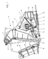
- FIG. 1 shows a schematic illustration of a jaw crusher according to the prior art with conventional sliding joints
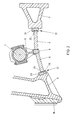
- 2 shows an enlarged representation of the toggle lever system in accordance with the innovation
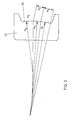
- FIG. 3 shows, on a further enlarged scale, a view of a rolling surface according to the innovation of a rolling joint of FIG. 2.
- a double toggle jaw crusher 1 is shown according to the prior art, on the housing 2, a bearing 3 for a bearing axis 4 is fixed.
- a movable crusher rocker 5 is swingingly mounted on the bearing axis 4 and is driven by toggle lever 6 via an eccentric shaft 7.
- the toggle levers 6 are acted upon in the region of a joint piece 8 via a connecting rod 9 and held in contact with the eccentric shaft 7 via a spring 10.
- By rotating the eccentric shaft 7, the toggle levers 6 are moved alternately into a more extended and an angled position, which results in a stroke of the breaker arm 5 in the direction of the double arrow 11.
- the crusher gap 12 can optionally be adjusted by appropriate adjustment of the stationary counter jaw 13.
- the support of the forces or the power transmission to the movable crusher rocker 5 via the toggle levers 6 takes place via spherical bearings 14 and 15.
- the spherical bearing 15 is supported on the crusher rear wall 16.
- a spring 17 is shown in FIG. 1, which acts on the breaker rocker 5 against the application of force by the toggle levers 6.
- Both the stationary counter jaw 13 and the crusher rocker 5 are each equipped with crushing jaws 18 and 19 designed as wearing parts.
- the wearing parts 18 and 19 can be fixed in a simple manner, as is indicated for the breaker arm by the pull rod 20.
- the toggle lever system is shown enlarged in FIG. 2, the reference numerals of FIG. 1 being retained for the same components.
- the toggle levers 6 are in turn acted upon by an eccentric shaft 7 via a connecting rod 9, a central joint piece 8 being provided.
- rolling joints 21 and 22 are provided, at least one of the rolling surfaces having a surface deviating from a circular cylindrical shape, the radius of which is different for different angular positions of the toggle levers, as shown in FIG Fig. 3 is shown in an enlarged scale.
- FIG. 2 the reference numerals of FIG. 1 being retained for the same components.
- the toggle levers 6 are in turn acted upon by an eccentric shaft 7 via a connecting rod 9, a central joint piece 8 being provided.
- rolling joints 21 and 22 are provided, at least one of the rolling surfaces having a surface deviating from a circular cylindrical shape, the radius of which is different for different angular positions of the toggle levers, as shown in FIG Fig. 3 is shown in an enlarged scale.
- FIG. 3 In the embodiment shown
- the rolling surface of the abutment component 23 on the movable crusher rocker 5 and the abutment component - 24, which in turn is fixed on the crusher rear wall 7, is designed with such a rolling surface deviating from a circular shape.
- the toggle levers 6 have essentially flat end surfaces 25 in the area of the rolling joints 21 and 22.
- a similar design of the end surfaces 25 of the toggle levers can be provided.
- it can also be in the area of the central joint piece 8 an appropriate design of the rolling surfaces can be selected.
- FIG. 2 For the sake of clarity, the components which are further required for the proper functioning and which do not relate to essential features of the innovation are not shown again in FIG. 2 and can be provided essentially analogously to the known design according to FIG. 1.
- the abutment component 23 is shown with its rolling surface 26 on a further enlarged scale, three chord areas s 1, s 2 and s 3 can be distinguished from one another, each corresponding to areas with different radius of curvature R 1, R 2 and R 3.
- the radii of curvature of the rolling surface 26 are chosen such that the smallest radius of curvature R3 was selected at the start of the stroke and in such a way with a relatively small amount of force, while a position of the angle lever, not shown, in a position closer to the extended position, a larger radius of curvature R1 due to the larger forces occurring is chosen.
Landscapes
- Engineering & Computer Science (AREA)
- Mechanical Engineering (AREA)
- Food Science & Technology (AREA)
- Crushing And Grinding (AREA)
- Pharmaceuticals Containing Other Organic And Inorganic Compounds (AREA)
- Saccharide Compounds (AREA)
Claims (4)
- Concasseur à mâchoires (1) comprenant une mâchoire (5) prenant appui sur un point fixe et une contre-mâchoire (5) pouvant être entraînée en un mouvement relatif alternatif (11) par rapport à cette mâchoire (5), en tournant autour d'un axe d'oscillation (4), dans lequel la mâchoire mobile est mise en mouvement par un arbre à excentrique (7) par l'intermédiaire de biellettes de genouillère (6), et où la transmission de la force des biellettes (6) de la genouillère s'effectue par l'intermédiaire d'articulations (21, 22) à mouvement de roulement, caractérisé en ce qu'au moins une articulation (21 à 22) à mouvement de roulement présente au moins une surface de roulement (26) dont la configuration s'écarte de la forme cylindrique à base circulaire et dont le rayon (R₁, R₂, R₃) est différent pour les différentes positions angulaires des biellettes de genouillère (6).
- Concasseur à mâchoires selon la revendication 1, caractérisé en ce que le rayon (R₁) de la courbure de la surface de roulement (26) est choisi plus grand dans une position angulaire des biellettes de genouillère (6) qui est plus proche de la position d'extension que dans les positions angulaires des biellettes de genouillère (6) qui sont plus éloignées de la position d'extension.
- Concasseur à mâchoires selon la revendication 1 ou 2, caractérisé en ce que les surfaces frontales (25) des extrémités des biellettes de genouillère (6) qui coopèrent avec les surfaces de roulement (26) sont constituées par des surfaces planes ou par des surfaces possédant une courbure progressive ou dégressive.
- Concasseur à mâcnoires selon la revendication 1, 2 ou 3, caractérisé en ce que le rapport entre le plus petit rayon de courbure (R₃) d'une surface de roulement (26) et le plus grand rayon de courbure (R₁) de la même surface de roulement (26) est d'au moins 1:1,5, de préférence d'environ 1:1,8 à 1:2,5.
Applications Claiming Priority (2)
| Application Number | Priority Date | Filing Date | Title |
|---|---|---|---|
| AT0038590A AT401477B (de) | 1990-02-20 | 1990-02-20 | Backenbrecher |
| AT385/90 | 1990-02-20 |
Publications (2)
| Publication Number | Publication Date |
|---|---|
| EP0444019A1 EP0444019A1 (fr) | 1991-08-28 |
| EP0444019B1 true EP0444019B1 (fr) | 1993-10-13 |
Family
ID=3489191
Family Applications (1)
| Application Number | Title | Priority Date | Filing Date |
|---|---|---|---|
| EP91890034A Revoked EP0444019B1 (fr) | 1990-02-20 | 1991-02-20 | Broyeur à mâchoires |
Country Status (3)
| Country | Link |
|---|---|
| EP (1) | EP0444019B1 (fr) |
| AT (2) | AT401477B (fr) |
| DE (2) | DE9006168U1 (fr) |
Families Citing this family (5)
| Publication number | Priority date | Publication date | Assignee | Title |
|---|---|---|---|---|
| NL9400521A (nl) * | 1994-03-30 | 1995-11-01 | Gerardus Cornelis Petrus Maria | Continu werkende (hydraulische-) breker voor het vergruizen van onder anderen steen-, beton-, asfaltdelen en dergelijke, monteerbaar aan een hydraulische graafmachine. |
| US8322643B2 (en) | 2010-07-23 | 2012-12-04 | Mining Technologies International Inc. | Rock crusher attachment |
| CN104069930B (zh) * | 2014-06-30 | 2016-01-06 | 山东莱钢建设有限公司 | 一种立轴拉杆护罩及其固定方法 |
| CN108144676A (zh) * | 2016-12-06 | 2018-06-12 | 郑州狮虎磨料磨具有限公司 | 一种新型颚式破碎机 |
| CN110404619B (zh) * | 2019-08-01 | 2021-05-11 | 山东耀华特耐科技有限公司 | 应用玄武岩的浇注料的生产设备 |
Family Cites Families (4)
| Publication number | Priority date | Publication date | Assignee | Title |
|---|---|---|---|---|
| GB773359A (en) * | 1954-10-14 | 1957-04-24 | Kloeckner Humboldt Deutz Ag | A jaw crusher |
| FR1269258A (fr) * | 1960-06-27 | 1961-08-11 | Ateliers Et Fonderies De Tamar | Perfectionnements aux concasseurs à mâchoires |
| DE1243954B (de) * | 1964-03-17 | 1967-07-06 | Weserhuette Ag Eisenwerk | Backenbrecher |
| SU967554A1 (ru) * | 1980-06-16 | 1982-10-23 | Томский инженерно-строительный институт | Распорна плита щековой дробилки |
-
1990
- 1990-02-20 AT AT0038590A patent/AT401477B/de not_active IP Right Cessation
- 1990-05-31 DE DE9006168U patent/DE9006168U1/de not_active Expired - Lifetime
-
1991
- 1991-02-20 DE DE91890034T patent/DE59100470D1/de not_active Revoked
- 1991-02-20 EP EP91890034A patent/EP0444019B1/fr not_active Revoked
- 1991-02-20 AT AT91890034T patent/ATE95729T1/de not_active IP Right Cessation
Also Published As
| Publication number | Publication date |
|---|---|
| ATE95729T1 (de) | 1993-10-15 |
| AT401477B (de) | 1996-09-25 |
| DE59100470D1 (de) | 1993-11-18 |
| EP0444019A1 (fr) | 1991-08-28 |
| ATA38590A (de) | 1996-02-15 |
| DE9006168U1 (de) | 1990-08-09 |
Similar Documents
| Publication | Publication Date | Title |
|---|---|---|
| DE3038865C1 (de) | Walzgeruest mit axial verschiebbaren Walzen | |
| EP0249801B1 (fr) | Laminoir pour la fabrication d'un feuillard de laminage | |
| DE2206912C3 (de) | Walzgerüst | |
| DE2919105A1 (de) | Walzwerk | |
| DE69303726T2 (de) | Kolbenbetätigungstangen in einer Dekompressionsvorrichtung zum Motorbremsen | |
| DE3624241A1 (de) | Walzwerk zur herstellung eines walzgutes, insbesondere eines walzbandes | |
| EP0444019B1 (fr) | Broyeur à mâchoires | |
| EP1811194A1 (fr) | Frein à disque | |
| DD145501A5 (de) | Vorrichtung zum axialen verschieben von konischen zwischenwalzen in einem mehrrollen-walzgeruest | |
| DE3107693A1 (de) | Walzgeruest | |
| EP0665067A1 (fr) | Cage de laminoir à cylindres multiples du type à montants de préférence avec serrage hydraulique direct | |
| AT407966B (de) | Schmiedemaschine | |
| DE3104263A1 (de) | "hebelwerkzeug mit progressiver uebersetzung" | |
| DE4034822C2 (de) | Walzenlagerung einer Zweiwalzen-Maschine | |
| DE3610889A1 (de) | Walzenbiegevorrichtung fuer ein walzwerk | |
| EP0256408A2 (fr) | Dispositif pour plier et balancer des cylindres de travail décalables axialement d'une cage quarto | |
| DE19512929C1 (de) | Walzgerüst mit Stütz-und Arbeitszwalzen zum Walzen von Blechen und Bändern | |
| DE2722625C2 (de) | Backenbrecher | |
| DD294521A5 (de) | Haupthebel fuer eine rotationsschaftmaschine, die mit hoher geschwindigkeit arbeitet | |
| DE3049080A1 (de) | Presswalze, deren durchbiegung einstellbar ist | |
| DE2825896A1 (de) | Walzwerk mit gestuetztem walzenaggregat | |
| DE2911424C2 (de) | Ein-Zahn-Ge triebe | |
| DE10027865C1 (de) | Vielwalzen-Walzwerk für Bandmaterial | |
| DE4106056C2 (de) | Walzbiegeeinrichtung für ein Walzgerüst | |
| DE69805149T2 (de) | Druckeinheit für oszillierende Walze |
Legal Events
| Date | Code | Title | Description |
|---|---|---|---|
| PUAI | Public reference made under article 153(3) epc to a published international application that has entered the european phase |
Free format text: ORIGINAL CODE: 0009012 |
|
| AK | Designated contracting states |
Kind code of ref document: A1 Designated state(s): AT DE FR GB IT |
|
| 17P | Request for examination filed |
Effective date: 19920108 |
|
| 17Q | First examination report despatched |
Effective date: 19930202 |
|
| GRAA | (expected) grant |
Free format text: ORIGINAL CODE: 0009210 |
|
| AK | Designated contracting states |
Kind code of ref document: B1 Designated state(s): AT DE FR GB IT |
|
| REF | Corresponds to: |
Ref document number: 95729 Country of ref document: AT Date of ref document: 19931015 Kind code of ref document: T |
|
| ITF | It: translation for a ep patent filed | ||
| REF | Corresponds to: |
Ref document number: 59100470 Country of ref document: DE Date of ref document: 19931118 |
|
| GBT | Gb: translation of ep patent filed (gb section 77(6)(a)/1977) |
Effective date: 19940117 |
|
| ET | Fr: translation filed | ||
| PLBI | Opposition filed |
Free format text: ORIGINAL CODE: 0009260 |
|
| 26 | Opposition filed |
Opponent name: FIRMA FERDINAND MOHR GMBH&CO. KG MAHL- UND VERSCHL Effective date: 19940528 |
|
| PGFP | Annual fee paid to national office [announced via postgrant information from national office to epo] |
Ref country code: GB Payment date: 19950116 Year of fee payment: 5 Ref country code: DE Payment date: 19950116 Year of fee payment: 5 |
|
| PGFP | Annual fee paid to national office [announced via postgrant information from national office to epo] |
Ref country code: FR Payment date: 19950120 Year of fee payment: 5 |
|
| PGFP | Annual fee paid to national office [announced via postgrant information from national office to epo] |
Ref country code: AT Payment date: 19950130 Year of fee payment: 5 |
|
| RDAG | Patent revoked |
Free format text: ORIGINAL CODE: 0009271 |
|
| STAA | Information on the status of an ep patent application or granted ep patent |
Free format text: STATUS: PATENT REVOKED |
|
| 27W | Patent revoked |
Effective date: 19950309 |
|
| GBPR | Gb: patent revoked under art. 102 of the ep convention designating the uk as contracting state |
Free format text: 950309 |