EP0443895B1 - Dispositif de verrouillage de deux tubes coaxiaux - Google Patents
Dispositif de verrouillage de deux tubes coaxiaux Download PDFInfo
- Publication number
- EP0443895B1 EP0443895B1 EP91400242A EP91400242A EP0443895B1 EP 0443895 B1 EP0443895 B1 EP 0443895B1 EP 91400242 A EP91400242 A EP 91400242A EP 91400242 A EP91400242 A EP 91400242A EP 0443895 B1 EP0443895 B1 EP 0443895B1
- Authority
- EP
- European Patent Office
- Prior art keywords
- tube
- tab
- groove
- tubes
- outer tube
- Prior art date
- Legal status (The legal status is an assumption and is not a legal conclusion. Google has not performed a legal analysis and makes no representation as to the accuracy of the status listed.)
- Expired - Lifetime
Links
Images


Classifications
-
- F—MECHANICAL ENGINEERING; LIGHTING; HEATING; WEAPONS; BLASTING
- F16—ENGINEERING ELEMENTS AND UNITS; GENERAL MEASURES FOR PRODUCING AND MAINTAINING EFFECTIVE FUNCTIONING OF MACHINES OR INSTALLATIONS; THERMAL INSULATION IN GENERAL
- F16L—PIPES; JOINTS OR FITTINGS FOR PIPES; SUPPORTS FOR PIPES, CABLES OR PROTECTIVE TUBING; MEANS FOR THERMAL INSULATION IN GENERAL
- F16L37/00—Couplings of the quick-acting type
- F16L37/08—Couplings of the quick-acting type in which the connection between abutting or axially overlapping ends is maintained by locking members
- F16L37/084—Couplings of the quick-acting type in which the connection between abutting or axially overlapping ends is maintained by locking members combined with automatic locking
- F16L37/098—Couplings of the quick-acting type in which the connection between abutting or axially overlapping ends is maintained by locking members combined with automatic locking by means of flexible hooks
- F16L37/0985—Couplings of the quick-acting type in which the connection between abutting or axially overlapping ends is maintained by locking members combined with automatic locking by means of flexible hooks the flexible hook extending radially inwardly from an outer part and engaging a bead, recess or the like on an inner part
-
- Y—GENERAL TAGGING OF NEW TECHNOLOGICAL DEVELOPMENTS; GENERAL TAGGING OF CROSS-SECTIONAL TECHNOLOGIES SPANNING OVER SEVERAL SECTIONS OF THE IPC; TECHNICAL SUBJECTS COVERED BY FORMER USPC CROSS-REFERENCE ART COLLECTIONS [XRACs] AND DIGESTS
- Y10—TECHNICAL SUBJECTS COVERED BY FORMER USPC
- Y10S—TECHNICAL SUBJECTS COVERED BY FORMER USPC CROSS-REFERENCE ART COLLECTIONS [XRACs] AND DIGESTS
- Y10S285/00—Pipe joints or couplings
- Y10S285/921—Snap-fit
Definitions
- the immobilization of two coaxial tubes can be sought, both with respect to a relative rotation than a translation, whenever it is desired to obtain an effective mechanical connection between the two tubes.
- US-A-3,933,378 has already sought to remedy the drawbacks of certain designed devices and has described a rapid connection of tubes, generally metallic, but the device proposed by this prior document, apart from being difficult to dismantle. 'it is used in congested areas, for example on a vehicle engine, does not allow an easy and visual control of the locking of the connection since the locking members risk being hidden by a cage fixed to the internal tube.
- the present invention therefore relates to a quick connection, of the aforementioned kind, ensuring by simple means the immobilization of two coaxial tubes, both vis-à-vis an axial translation as a relative rotation, and prohibiting any possibility incorrect mounting due to certain "angular indexing".
- a connection will be called “locking device” and it will be noted now that it will be advantageously used on devices for connecting two conduits, such as those described in application EP-A-0440564 (published 07.08. 91)
- Such a locking device comprises, in known manner, a longitudinal tab, elastically flexible in the radial direction, and connected to the external tube.
- This tab has at least one zone capable of coming into axial abutment, after fitting of the tubes, with a shoulder provided in correspondence on the external face of the internal tube and projecting radially from the latter.
- the locking device is constituted by the combination of simple arrangements of the ends of the inner and outer tubes, intended to be fitted into one another.
- the wall of the outer tube has a groove, open to the end of the tube, the lateral edges of which are parallel to the axis of the tube.
- the outer face of the inner tube has two radially projecting guide surfaces, said surfaces being parallel to the axis of the tube and spaced from each other by a distance substantially equal to that separating the edges. lateral of the groove of the outer tube.
- the free end of the flexible longitudinal tab, or locking tab is located substantially in the transverse plane of the end of the outer tube.
- the locking device may comprise two or more flexible tabs, as well as two or more grooves and pairs of guide surfaces, in sufficient number.
- the multiplication of tube end fittings will not be essential.
- FIG. 1 If we refer first to Figures 1 to 4 we see a internal tube 1 intended to be fitted into an external tube 2 to constitute a set of two coaxial tubes.
- the inside diameter of the tube 2 is substantially equal to the outside diameter of the tube 1 .
- the walls of these two tubes have been shown with a relatively large thickness to facilitate the explanations of the arrangements provided at their opposite ends, but it is obvious, as will be emphasized later, that the invention does not impose any particular requirement on this regard.
- the boss 3 has a generally elongated shape in the axial direction of the tube 1 and its lateral faces 3 a and 3 b are parallel to the axis of the tube and project from a height h relative to the external surface 1 a .
- the protrusion 4 generally of smaller dimensions than the boss 3 , may have a substantially square shape, at least one of its axial ends 4 a and 4 b , and in particular the end 4 a which is the most distant from the end 1b of the tube, being located in a transverse plane of the tube 1 , so as to constitute a transverse shoulder.
- zone 4 b of the protuberance 4 the axially closest to the end 1 a of the tube, is however more distant from this end than the corresponding zone 3 c of the boss 3 . The reasons for this arrangement will appear later.
- a groove 5 On the inner face of the outer tube 2 is formed a groove 5 whose lateral edges 5 a and 5 b are parallel to the axis of the tube and are spaced from each other by a distance e substantially equal to that separating the opposite lateral faces 3 a and 3 b of the boss 3 .
- the depth of the groove is at least equal to the radial projection h of the side faces 3 a and 3 b .
- the groove 5 opens at the end 2a of the tube 2 and its axial length is preferably at least equal to that of the boss 3. It is determined by an end face 5 c , the position of which will be specified below.
- the tab 7 is fixed, in the vicinity of its internal end 7 a , to the wall of the tube 2 and its external end 7 b is situated substantially in the transverse plane of the end 2 a of the tube 2 , preferably inside of the tube.
- the shape of the tab 7 and / or its means of attachment to the wall of the tube make it elastically flexible or mobile, around a transverse axis located near its internal end 7 a , inside the recess 6 .
- the tab 7 has a housing 8 , for example of shape substantially identical to that of the protuberance 4 .
- the housing 8 can be constituted by a hole passing through the thickness of the tab.
- the depth of the housing 8 is substantially equal to the radial projection of the protrusion 4 with respect to the outer surface 1a of the tube 1.
- At least one of the longitudinal ends 8 a and 8 b of the housing 8 in particular the end 8 a close to the end 7 b of the tab 7 , is located in a transverse plane of the tube 1 , perpendicular to its internal surface .
- the axial distance between the two ends 8 a and 8 b is preferably substantially equal to that which separates the two axial ends 4 a and 4 b from the protuberance 4 .
- the axial ends 4a and 4b of the protrusion 8 and 8b of the housing are perpendicular to the outer surfaces or inner tubes, they constitute complementary areas of axial support, ensuring the axial immobilization of the two tubes with respect to each other, both in the direction of the fitting and in that of the disengagement.
- the axial ends 4 a and 8 a are shaped so as to constitute complementary zones of axial support, ensuring immobilization in the direction of disengagement.
- other means could be used.
- the length of the groove 5 could be determined so that its end 5 a constitutes an axial support zone for the anterior longitudinal end 3 c of the boss 3 , after the shoulder 4 a has reached or even slightly exceeded the end 8a of the housing 8.
- the outer tube 12 is an appendage made of thin sheet metal, fixed to the end of a flexible pipe under the conditions set out in the aforementioned patent application. It is intended to be fitted onto a rigid end piece or internal tube 11 , generally made of plastic.
- a rigid end piece or internal tube 11 On the outer surface 11 a there is the protrusion 14 which is however associated with two bosses 13 - 13 ′ arranged symmetrically to one another with respect to the diametral plane passing through the protrusion 14 . Note, however, that all of the two bosses 13 - 13 ′ correspond a distance e 1 between their opposite lateral faces 13 b - 13 ′ a .
- the zone 14b of the protuberance 14 closest to the end 11b of the tube 11 , is more distant from this end than the corresponding zones 13c bosses 13 .
- the transverse shoulder 14 a is substantially perpendicular to the outer surface 11 a of the tube, while the opposite end 14 b of the protuberance is preferably constituted by an inclined ramp.
- the outer tube 12 has a longitudinal groove 15 , the two lateral edges 15 a - 15 b of which are spaced by a distance e 1 substantially equal to that separating the opposite lateral faces 13 b - 13 ′ has bosses 13 - 13 ′ .
- a longitudinal tab 17 whose free end 17 b is slightly curved towards the outside.
- the tab 17 is obtained by a suitable cutting of the wall of the external tube 12 to which it remains fixed by its end 17 has , preferably of smaller width, which constitutes an elastic zone of folding. In the free state, and as can be seen in FIG. 5 b , the tab 17 is located on the periphery of the tube 12 .
- the longitudinal edges 17 c of the tab 17 are parallel to the edges 15 a - 15 b of the groove and define with them two secondary grooves 15 d whose width is close to that of each of the bosses 13 - 13 ′ .
- the tab 17 has a hole 18 in its central part, the shape of which preferably corresponds to that of the protuberance 14 . More precisely, the transverse edge 18 a is perpendicular to the edges 15 a - 15 b of the groove.
- the positioning of the locking device is similar to that which has been described above.
- the complete fitting of the tube 12 on the tube 11 will obviously require the correct presentation of the edges 15 a - 15 b of the groove 15 in alignment with the opposite lateral faces 13 b - 13 ′ has bosses 13 - 13 ′ (position shown in dotted line in Figure 6 b ).
- an appropriate indexing member designated by the reference A.
- the immobilization in rotation of the two tubes 11 and 12 is ensured by the cooperation of the edges 15 a - 15 b of the groove 15 and the lateral faces 13 b - 13 ′ has bosses 13 - 13 ′ , while the axial immobilization the disengagement is obtained by mutual support of the edge 18 a of the hole 18 and the shoulder 14 a of the protrusion 14 .
- Axial immobilization in the fitting direction can be obtained by pressing the bosses 13 - 13 ′ on the bottom 15 c of the groove 15 or by any other suitable support of the tube 11 on a stopper linked to the tube 12 , such as that indicated in B in FIG. 7.
- FIGS. 9 to 12 we see a second variant embodiment, similar to that which has just been described with reference to FIGS. 5 to 8. Like the previous one, it will advantageously be associated with a device for connecting a flexible pipe to a rigid end piece such as that which is the subject of the aforementioned patent application.
- the elements already described have the same references, again increased by 10.
- the outer tube consists of a thin metal sheet, which can be easily cut and stamped.
- the rigid end piece 21 On the outer surface 21 a of the rigid end piece 21 , which constitutes the internal tube, there are two elongated bosses 23 and 23 ′ whose opposite lateral faces 23 b - 23 ′ a radially protrude and are parallel to the axis of the tube, being spaced from each other by a transverse distance e ′ 1 .
- the longitudinal ends of these bosses are located in two transverse planes of the tube, preferably, as shown in the drawing, in the same transverse plane for each pair of corresponding ends.
- the ends 23 c and 23 ′ c the closest to the end 21 b of the tube, advantageously have the shape of a ramp, while the ends 24 a and 24 ′ a constitute shoulders radially projecting from the external surface.
- bosses 23 and 23 ′ may constitute only one of them, they will preferably be distinct from each other, their lateral faces 23 a and 23 ′ b being separated by a small distance so as to spare a longitudinal notch 21 d whose utility will appear later.
- the outer tube 22 has a longitudinal groove 25 , the longitudinal edges 25 a - 25 b are parallel to the axis of the tube and are spaced a distance substantially equal to that separating the opposite lateral faces 23 b - 23 ′ has bosses 23 - 23 ′ .
- the edges 25 a and 25 b of the groove are provided with small tabs 25 c and 25 d perpendicular to the plane of the groove and improving, as well as it will be specified later, the role of guiding the edges of the groove.
- a bridge 29 supporting the flexible longitudinal tab 27 is fixed to the external tube 22 above the groove 25 .
- This trigger guard preferably made of spring steel, has on each of its lateral edges a fold 29 a whose left end, slightly bent, is supported (fig. 9 b ) on a protuberance 22 a linked to the tube 22 while its right end is simply crimped on the end edge 22 b , folded back, of the tube 22 (fig. 10 b ).
- the tab 27 is constituted by a fold back of the upper face of the trigger guard 29 connecting to it by a loop 27 a , clearly visible in section in FIG. 9 b . It has a width substantially greater than that of the groove 25 as seen in Figure 10b . At its free end, located substantially in the transverse plane of the end edge 22 b of the tube, the tab 27 has a hook 27 c folded over the upper face of the trigger guard 29 .
- the tab 27 has two openings 28 and 28 ′ whose outline corresponds to that of the bosses 23 and 23 ′ .
- the transverse edges 28 and 28 ′ a those closest to the terminal edge 22 b of the outer tube, are preferably in the same transverse plane, while the opposite longitudinal edges 28 b and 28 ′ b are advantageously offset laterally relative to the edges 25 a - 25 b of the groove, thus allowing the passage of the legs 25 c and 25 d in the openings 28 and 28 ′ .
- the tab 27 rests on the longitudinal edges of the groove 25 and is elastically held there by the spring which constitutes the loop 27 a .
- the positioning of the locking device is similar to that which has been described above.
- the fitting of the tube 21 into the tube 22 first causes the lifting of tab 27 by ramps 23 c - 23 ′ c of the bosses.
- the lateral faces 23 b - 23 ′ a of these are guided longitudinally by the edges 25 a - 25 b of the groove and especially by their small tabs 25 c - 25 d .
- the transverse edges 28 a - 28 ′ has openings in the tab 27 come to bear axially behind the shoulders 24 a - 24 ′ has bosses 23 - 23 ′ , while the tab 27 resumes the position it occupied in the free state under the effect of its spring 27 a (fig. 11).
- the two tubes are then immobilized axially and in rotation, both with respect to the disengagement and in the direction of fitting.
- the arrangements described above will again be usable.
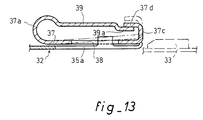
- the bridge 39 is disposed above the longitudinal groove formed in the outer tube 32 and the tab 37 is constituted by a fold connected to the bridge by the loop 37 a .
- the tab 37 ends with a hook 37 c folded over the upper face of the trigger guard.
- the latter has a recess 39 a whose depth corresponds substantially to the thickness of the sheet and whose width (in the direction perpendicular to the figure) is advantageously close to that of the hook 37 c .
- This has a fold 37 d whose plane is parallel to that of the tab 37 .
- the boss 33 raises the tab 37 and its fold 37 d protrudes above the face upper of trigger guard 39 (position in dotted line). After having been guided by the longitudinal edge 35 a of the groove, the boss 33 comes opposite the opening 38 of the tab 37 . Under the effect of its spring 37 a , the tab 37 returns to the position shown in solid lines in the figure, which ensures locking.
- the trigger guard 49 disposed above the groove of the external tube 42 supports the tab 47 by means of the loop 47 a forming a spring.
- the tab 47 has a recess 47 b , the usefulness of which will appear further on, while its terminal hook 47 c is located below the terminal edge 49 b of the trigger guard 49 .
- a jumper 51 made of elastic material, preferably made of spring steel, consists of a sheet folded in a U shape surrounding the trigger guard 49 and its tab 47 .
- the bottom of the U is located in the area of the loop 47 a and has a recess 51 a , clearly visible in FIG. 15, allowing the passage of the loop 47 a .
- the lower branch 51b of the rider is situated below the tab 47 and extends below the recess 47 b of the tab.
- the upper branch 51c of the jumper extends above the upper face of the trigger guard 49 . In its central part, this upper branch 51 c is capable of being engaged (FIGS. 14 and 15) with the end fold 47 e of the hook 47 c of the tab 47 , however, on either side of this central part , it is extended by hooks 51 d directed towards the lower branch 51 b .
- the jumper 51 which has just been described constitutes a member mounted to slide axially with respect to the trigger guard 49 and to its tab 47 and likely to be engaged with an element of the latter.
- the branches 51 b - 51 c of the jumper 51 are slightly divergent, so that they undergo a elastic deformation when they are arranged parallel to each other ( Figure 14).
- the rider 51 is also a spring which tends to separate from one another the ends of its legs 51 b and 51 c.
- the lower branch 51 b of the rider has a terminal edge 51 e comprising, below the openings 48 - 48 ′ of the tab 47 , two longitudinal projections 51 f and 51 g , closer to the end of the outer tube 42 than is the rest of the edge 51 e .
- the jumper 51 Before the fitting of the tubes 41 and 42 , the jumper 51 is in the position shown in FIG. 14, and the central central part of its upper branch 51 c is supported under the terminal fold 47 e of the tab 47 . The latter is therefore raised, against the spring constituted by its loop 47 a , above the groove 45 , while the upper branch 51 c of the jumper is applied to the upper face of the trigger guard 49 and that the spring constituted by the jumper itself is compressed.
- the upper branch 51 c of the rider relaxes elastically by taking a divergent position relative to the lower branch 51 b .
- This movement is nevertheless limited thanks to the presence of the lateral hooks 51 d which come to take support under the trigger guard 49 .
- This position of the jumper 51 allows visual and easy control of the locking by the operator.
- the jumper 51 will pivot instead of sliding, again preventing the release of the elements 51 c and 47 e and attracting thus the operator's attention.
Priority Applications (1)
| Application Number | Priority Date | Filing Date | Title |
|---|---|---|---|
| AT91400242T ATE81900T1 (de) | 1990-02-02 | 1991-02-01 | Vorrichtung zum kuppeln von zwei koaxialen rohren. |
Applications Claiming Priority (2)
| Application Number | Priority Date | Filing Date | Title |
|---|---|---|---|
| FR9001260 | 1990-02-02 | ||
| FR9001260 | 1990-02-02 |
Publications (2)
| Publication Number | Publication Date |
|---|---|
| EP0443895A1 EP0443895A1 (fr) | 1991-08-28 |
| EP0443895B1 true EP0443895B1 (fr) | 1992-10-28 |
Family
ID=9393361
Family Applications (1)
| Application Number | Title | Priority Date | Filing Date |
|---|---|---|---|
| EP91400242A Expired - Lifetime EP0443895B1 (fr) | 1990-02-02 | 1991-02-01 | Dispositif de verrouillage de deux tubes coaxiaux |
Country Status (12)
| Country | Link |
|---|---|
| US (1) | US5249830A (ja) |
| EP (1) | EP0443895B1 (ja) |
| JP (1) | JPH04504752A (ja) |
| AT (1) | ATE81900T1 (ja) |
| BR (1) | BR9105811A (ja) |
| CA (1) | CA2065236A1 (ja) |
| DE (1) | DE69100007T2 (ja) |
| DK (1) | DK0443895T3 (ja) |
| ES (1) | ES2036116T3 (ja) |
| GR (1) | GR3006603T3 (ja) |
| HU (1) | HU211404B (ja) |
| WO (1) | WO1991011650A1 (ja) |
Families Citing this family (11)
| Publication number | Priority date | Publication date | Assignee | Title |
|---|---|---|---|---|
| DE4416311A1 (de) * | 1994-05-09 | 1995-11-16 | Itw Oberflaechentechnik Gmbh | Sprühgerät-Befestigungsvorrichtung |
| US5465647A (en) * | 1994-11-14 | 1995-11-14 | Polygon Company | Fluid cylinder end cap assembly |
| US5651303A (en) * | 1994-11-14 | 1997-07-29 | Polygon Company | Fluid cylinder end cap assembly |
| US5716081A (en) * | 1996-03-11 | 1998-02-10 | Automotive Products (Usa), Inc. | Spring clip for quick connect coupling |
| US6032328A (en) * | 1998-02-10 | 2000-03-07 | Rexair, Inc. | Crevice cleaning tool for a vacuum cleaner apparatus |
| US6367974B1 (en) * | 1999-04-19 | 2002-04-09 | Peter Lin | Thermocouple apparatus and well for containers having a flanged access opening |
| US7490620B2 (en) * | 2004-02-23 | 2009-02-17 | Tyco Healthcare Group Lp | Fluid conduit connector apparatus |
| US7871387B2 (en) | 2004-02-23 | 2011-01-18 | Tyco Healthcare Group Lp | Compression sleeve convertible in length |
| US7967342B2 (en) * | 2005-03-01 | 2011-06-28 | Ti Group Automotive Systems, Llc | Anti-rotation quick connector |
| US8257286B2 (en) | 2006-09-21 | 2012-09-04 | Tyco Healthcare Group Lp | Safety connector apparatus |
| US8257287B2 (en) * | 2008-03-20 | 2012-09-04 | Tyco Healthcare Group Lp | Safety connector assembly |
Family Cites Families (16)
| Publication number | Priority date | Publication date | Assignee | Title |
|---|---|---|---|---|
| US753096A (en) * | 1904-02-23 | Peters xx | ||
| GB190609899A (en) * | 1905-06-27 | 1906-10-25 | Earl Judson Wheler De Foreest | Improvements in and relating to Hose Couplings. |
| US2184881A (en) * | 1937-03-19 | 1939-12-26 | P A Geier Co | Tubular coupling for suction cleaners and the like |
| US2789839A (en) * | 1952-08-27 | 1957-04-23 | Bissell Carpet Sweeper Co | Spring detent engaging means for carpet sweeper sectional handle |
| BE635043A (ja) * | 1962-07-16 | |||
| US3245698A (en) * | 1963-11-04 | 1966-04-12 | Westinghouse Electric Corp | Latching means |
| US3244437A (en) * | 1964-01-28 | 1966-04-05 | Electrolux Corp | Adjustable length vacuum cleaner wand |
| SE7416373L (ja) * | 1974-01-10 | 1975-07-11 | Eric G Doubleday | |
| US3933378A (en) * | 1974-11-29 | 1976-01-20 | Ford Motor Company | Quick-connect tubing coupling |
| DE2921607C2 (de) * | 1979-05-28 | 1981-10-08 | Ford-Werke AG, 5000 Köln | Steckverbindung für Schlauchleitungen, insbesondere in Kraftfahrzeuen |
| US4448470A (en) * | 1981-12-28 | 1984-05-15 | The Bendix Corporation | Coupling member and an electrical connector |
| US4618195A (en) * | 1985-06-03 | 1986-10-21 | Whirlpool Corporation | Vacuum cleaner hose coupling |
| US4915421A (en) * | 1988-03-30 | 1990-04-10 | Itt Corporation | Quick connector assembly |
| DE3815172C1 (ja) * | 1988-05-04 | 1990-03-22 | Rasmussen Gmbh, 6457 Maintal, De | |
| US5112084A (en) * | 1989-02-07 | 1992-05-12 | Usui Kokusai Sangyo Kaisha, Ltd. | Connector for small-diameter piping |
| US5104253A (en) * | 1990-06-06 | 1992-04-14 | Chrysler Corporation | Cable assembly, lock therefor |
-
1991
- 1991-02-01 JP JP3503780A patent/JPH04504752A/ja active Pending
- 1991-02-01 EP EP91400242A patent/EP0443895B1/fr not_active Expired - Lifetime
- 1991-02-01 HU HU9200817A patent/HU211404B/hu not_active IP Right Cessation
- 1991-02-01 CA CA002065236A patent/CA2065236A1/en not_active Abandoned
- 1991-02-01 AT AT91400242T patent/ATE81900T1/de not_active IP Right Cessation
- 1991-02-01 DK DK91400242.3T patent/DK0443895T3/da active
- 1991-02-01 US US07/768,430 patent/US5249830A/en not_active Expired - Fee Related
- 1991-02-01 DE DE9191400242T patent/DE69100007T2/de not_active Expired - Fee Related
- 1991-02-01 WO PCT/FR1991/000066 patent/WO1991011650A1/fr active Application Filing
- 1991-02-01 ES ES199191400242T patent/ES2036116T3/es not_active Expired - Lifetime
- 1991-02-01 BR BR919105811A patent/BR9105811A/pt not_active Application Discontinuation
-
1992
- 1992-12-21 GR GR920403011T patent/GR3006603T3/el unknown
Also Published As
| Publication number | Publication date |
|---|---|
| JPH04504752A (ja) | 1992-08-20 |
| GR3006603T3 (ja) | 1993-06-30 |
| ATE81900T1 (de) | 1992-11-15 |
| HUT67481A (en) | 1995-04-28 |
| HU211404B (en) | 1995-11-28 |
| CA2065236A1 (en) | 1991-08-03 |
| DK0443895T3 (da) | 1993-02-22 |
| EP0443895A1 (fr) | 1991-08-28 |
| DE69100007T2 (de) | 1993-05-13 |
| WO1991011650A1 (fr) | 1991-08-08 |
| HU9200817D0 (en) | 1992-08-28 |
| BR9105811A (pt) | 1992-08-04 |
| ES2036116T3 (es) | 1993-05-01 |
| US5249830A (en) | 1993-10-05 |
| DE69100007D1 (de) | 1992-12-03 |
Similar Documents
| Publication | Publication Date | Title |
|---|---|---|
| EP0911565B1 (fr) | Connexion rapide pour emmanchement d'un tube rigide dans un embout | |
| EP0511891B1 (fr) | Elément de connexion pour le raccordement rapide d'un tube | |
| EP0443895B1 (fr) | Dispositif de verrouillage de deux tubes coaxiaux | |
| BE898358A (fr) | Structure de serrage sans oreille. | |
| FR2569337A1 (fr) | Construction d'une fixation liberable utilisable notamment dans le domaine des bijoux personnels | |
| FR2751722A1 (fr) | Dispositif de fixation destine a assujettir un organe de jonction de tubes a une plaquette qu'il traverse par une ouverture associee | |
| FR2473151A1 (fr) | Dispositif de raccordement de tuyaux | |
| EP0493182A1 (fr) | Collier de fixation | |
| FR2857709A1 (fr) | Mousqueton a deux doigts opposes | |
| EP0296919A1 (fr) | Collier de serrage | |
| FR2685614A1 (fr) | Bracelet a maillons notamment pour montre. | |
| EP0060748B1 (fr) | Dispositif d'arrêt, notamment pour porte de véhicule automobile | |
| FR2658899A1 (fr) | Dispositif d'accouplement et de verrouillage automatique de deux tubes coaxiaux. | |
| EP3795878B1 (fr) | Collier de serrage | |
| CH689417A5 (fr) | Anneau ouvrable muni d'un fermoir. | |
| WO2003014618A1 (fr) | Ensemble d'eclairage pour phare de vehicule | |
| FR2540198A1 (fr) | Agrafe de fixation a poussee axiale pour boulon traversant un element structurel | |
| FR2662488A1 (fr) | Collier de serrage a reserve de capacite. | |
| EP0437639B1 (fr) | Joint d'étanchéité de la jonction de deux tronçons d'un tapis transporteur et dispositif de jonction comportant un tel joint | |
| EP0410842B1 (fr) | Raccord rapide | |
| EP0603063B1 (fr) | Perfectionnements aux pièces de fixation monobloc destinées à être fixées sur la tête crantée d'une tige | |
| EP0208582B1 (fr) | Mandrin d'enroulement notamment pour sangle de sécurité | |
| WO1998000665A1 (fr) | Collier de serrage filaire | |
| FR2630174A1 (fr) | Ensemble d'accostage pour butee de debrayage, notamment pour vehicule automobile | |
| FR2630070A1 (fr) | Balai d'essuie-glace comportant un dispositif de connexion perfectionne d'un etrier principal sur un etrier secondaire |
Legal Events
| Date | Code | Title | Description |
|---|---|---|---|
| PUAI | Public reference made under article 153(3) epc to a published international application that has entered the european phase |
Free format text: ORIGINAL CODE: 0009012 |
|
| AK | Designated contracting states |
Kind code of ref document: A1 Designated state(s): AT BE CH DE DK ES FR GB GR IT LI LU NL SE |
|
| 17P | Request for examination filed |
Effective date: 19910726 |
|
| 17Q | First examination report despatched |
Effective date: 19920212 |
|
| GRAA | (expected) grant |
Free format text: ORIGINAL CODE: 0009210 |
|
| AK | Designated contracting states |
Kind code of ref document: B1 Designated state(s): AT BE CH DE DK ES FR GB GR IT LI LU NL SE |
|
| REF | Corresponds to: |
Ref document number: 81900 Country of ref document: AT Date of ref document: 19921115 Kind code of ref document: T |
|
| ITF | It: translation for a ep patent filed |
Owner name: JACOBACCI & PERANI S.P.A. |
|
| REF | Corresponds to: |
Ref document number: 69100007 Country of ref document: DE Date of ref document: 19921203 |
|
| GBT | Gb: translation of ep patent filed (gb section 77(6)(a)/1977) |
Effective date: 19930114 |
|
| REG | Reference to a national code |
Ref country code: DK Ref legal event code: T3 |
|
| REG | Reference to a national code |
Ref country code: ES Ref legal event code: FG2A Ref document number: 2036116 Country of ref document: ES Kind code of ref document: T3 |
|
| REG | Reference to a national code |
Ref country code: GR Ref legal event code: FG4A Free format text: 3006603 |
|
| PLBE | No opposition filed within time limit |
Free format text: ORIGINAL CODE: 0009261 |
|
| STAA | Information on the status of an ep patent application or granted ep patent |
Free format text: STATUS: NO OPPOSITION FILED WITHIN TIME LIMIT |
|
| 26N | No opposition filed | ||
| PGFP | Annual fee paid to national office [announced via postgrant information from national office to epo] |
Ref country code: AT Payment date: 19940124 Year of fee payment: 4 |
|
| PGFP | Annual fee paid to national office [announced via postgrant information from national office to epo] |
Ref country code: GR Payment date: 19940127 Year of fee payment: 4 |
|
| PGFP | Annual fee paid to national office [announced via postgrant information from national office to epo] |
Ref country code: ES Payment date: 19940216 Year of fee payment: 4 Ref country code: CH Payment date: 19940216 Year of fee payment: 4 |
|
| PGFP | Annual fee paid to national office [announced via postgrant information from national office to epo] |
Ref country code: SE Payment date: 19940217 Year of fee payment: 4 |
|
| PGFP | Annual fee paid to national office [announced via postgrant information from national office to epo] |
Ref country code: DE Payment date: 19940224 Year of fee payment: 4 |
|
| PGFP | Annual fee paid to national office [announced via postgrant information from national office to epo] |
Ref country code: FR Payment date: 19940225 Year of fee payment: 4 |
|
| PGFP | Annual fee paid to national office [announced via postgrant information from national office to epo] |
Ref country code: NL Payment date: 19940228 Year of fee payment: 4 Ref country code: LU Payment date: 19940228 Year of fee payment: 4 |
|
| PGFP | Annual fee paid to national office [announced via postgrant information from national office to epo] |
Ref country code: BE Payment date: 19940309 Year of fee payment: 4 |
|
| EPTA | Lu: last paid annual fee | ||
| PGFP | Annual fee paid to national office [announced via postgrant information from national office to epo] |
Ref country code: DK Payment date: 19940331 Year of fee payment: 4 |
|
| EAL | Se: european patent in force in sweden |
Ref document number: 91400242.3 |
|
| PG25 | Lapsed in a contracting state [announced via postgrant information from national office to epo] |
Ref country code: LU Free format text: LAPSE BECAUSE OF NON-PAYMENT OF DUE FEES Effective date: 19950201 Ref country code: GB Effective date: 19950201 Ref country code: DK Effective date: 19950201 Ref country code: AT Effective date: 19950201 |
|
| REG | Reference to a national code |
Ref country code: DK Ref legal event code: EBP |
|
| PG25 | Lapsed in a contracting state [announced via postgrant information from national office to epo] |
Ref country code: SE Effective date: 19950202 Ref country code: ES Free format text: LAPSE BECAUSE OF NON-PAYMENT OF DUE FEES Effective date: 19950202 |
|
| PG25 | Lapsed in a contracting state [announced via postgrant information from national office to epo] |
Ref country code: LI Effective date: 19950228 Ref country code: CH Effective date: 19950228 Ref country code: BE Effective date: 19950228 |
|
| BERE | Be: lapsed |
Owner name: ETS CAILLAU Effective date: 19950228 |
|
| PG25 | Lapsed in a contracting state [announced via postgrant information from national office to epo] |
Ref country code: GR Free format text: THE PATENT HAS BEEN ANNULLED BY A DECISION OF A NATIONAL AUTHORITY Effective date: 19950831 |
|
| PG25 | Lapsed in a contracting state [announced via postgrant information from national office to epo] |
Ref country code: NL Effective date: 19950901 |
|
| GBPC | Gb: european patent ceased through non-payment of renewal fee |
Effective date: 19950201 |
|
| PG25 | Lapsed in a contracting state [announced via postgrant information from national office to epo] |
Ref country code: FR Effective date: 19951031 |
|
| REG | Reference to a national code |
Ref country code: GR Ref legal event code: MM2A Free format text: 3006603 |
|
| NLV4 | Nl: lapsed or anulled due to non-payment of the annual fee |
Effective date: 19950901 |
|
| PG25 | Lapsed in a contracting state [announced via postgrant information from national office to epo] |
Ref country code: DE Effective date: 19951101 |
|
| EUG | Se: european patent has lapsed |
Ref document number: 91400242.3 |
|
| REG | Reference to a national code |
Ref country code: FR Ref legal event code: ST |
|
| REG | Reference to a national code |
Ref country code: ES Ref legal event code: FD2A Effective date: 19990503 |
|
| PG25 | Lapsed in a contracting state [announced via postgrant information from national office to epo] |
Ref country code: IT Free format text: LAPSE BECAUSE OF NON-PAYMENT OF DUE FEES;WARNING: LAPSES OF ITALIAN PATENTS WITH EFFECTIVE DATE BEFORE 2007 MAY HAVE OCCURRED AT ANY TIME BEFORE 2007. THE CORRECT EFFECTIVE DATE MAY BE DIFFERENT FROM THE ONE RECORDED. Effective date: 20050201 |