EP0443895B1 - Coupling device for two coaxial tubes - Google Patents
Coupling device for two coaxial tubes Download PDFInfo
- Publication number
- EP0443895B1 EP0443895B1 EP91400242A EP91400242A EP0443895B1 EP 0443895 B1 EP0443895 B1 EP 0443895B1 EP 91400242 A EP91400242 A EP 91400242A EP 91400242 A EP91400242 A EP 91400242A EP 0443895 B1 EP0443895 B1 EP 0443895B1
- Authority
- EP
- European Patent Office
- Prior art keywords
- tube
- tab
- groove
- tubes
- outer tube
- Prior art date
- Legal status (The legal status is an assumption and is not a legal conclusion. Google has not performed a legal analysis and makes no representation as to the accuracy of the status listed.)
- Expired - Lifetime
Links
Images


Classifications
-
- F—MECHANICAL ENGINEERING; LIGHTING; HEATING; WEAPONS; BLASTING
- F16—ENGINEERING ELEMENTS AND UNITS; GENERAL MEASURES FOR PRODUCING AND MAINTAINING EFFECTIVE FUNCTIONING OF MACHINES OR INSTALLATIONS; THERMAL INSULATION IN GENERAL
- F16L—PIPES; JOINTS OR FITTINGS FOR PIPES; SUPPORTS FOR PIPES, CABLES OR PROTECTIVE TUBING; MEANS FOR THERMAL INSULATION IN GENERAL
- F16L37/00—Couplings of the quick-acting type
- F16L37/08—Couplings of the quick-acting type in which the connection between abutting or axially overlapping ends is maintained by locking members
- F16L37/084—Couplings of the quick-acting type in which the connection between abutting or axially overlapping ends is maintained by locking members combined with automatic locking
- F16L37/098—Couplings of the quick-acting type in which the connection between abutting or axially overlapping ends is maintained by locking members combined with automatic locking by means of flexible hooks
- F16L37/0985—Couplings of the quick-acting type in which the connection between abutting or axially overlapping ends is maintained by locking members combined with automatic locking by means of flexible hooks the flexible hook extending radially inwardly from an outer part and engaging a bead, recess or the like on an inner part
-
- Y—GENERAL TAGGING OF NEW TECHNOLOGICAL DEVELOPMENTS; GENERAL TAGGING OF CROSS-SECTIONAL TECHNOLOGIES SPANNING OVER SEVERAL SECTIONS OF THE IPC; TECHNICAL SUBJECTS COVERED BY FORMER USPC CROSS-REFERENCE ART COLLECTIONS [XRACs] AND DIGESTS
- Y10—TECHNICAL SUBJECTS COVERED BY FORMER USPC
- Y10S—TECHNICAL SUBJECTS COVERED BY FORMER USPC CROSS-REFERENCE ART COLLECTIONS [XRACs] AND DIGESTS
- Y10S285/00—Pipe joints or couplings
- Y10S285/921—Snap-fit
Definitions
- the immobilization of two coaxial tubes can be sought, both with respect to a relative rotation than a translation, whenever it is desired to obtain an effective mechanical connection between the two tubes.
- US-A-3,933,378 has already sought to remedy the drawbacks of certain designed devices and has described a rapid connection of tubes, generally metallic, but the device proposed by this prior document, apart from being difficult to dismantle. 'it is used in congested areas, for example on a vehicle engine, does not allow an easy and visual control of the locking of the connection since the locking members risk being hidden by a cage fixed to the internal tube.
- the present invention therefore relates to a quick connection, of the aforementioned kind, ensuring by simple means the immobilization of two coaxial tubes, both vis-à-vis an axial translation as a relative rotation, and prohibiting any possibility incorrect mounting due to certain "angular indexing".
- a connection will be called “locking device” and it will be noted now that it will be advantageously used on devices for connecting two conduits, such as those described in application EP-A-0440564 (published 07.08. 91)
- Such a locking device comprises, in known manner, a longitudinal tab, elastically flexible in the radial direction, and connected to the external tube.
- This tab has at least one zone capable of coming into axial abutment, after fitting of the tubes, with a shoulder provided in correspondence on the external face of the internal tube and projecting radially from the latter.
- the locking device is constituted by the combination of simple arrangements of the ends of the inner and outer tubes, intended to be fitted into one another.
- the wall of the outer tube has a groove, open to the end of the tube, the lateral edges of which are parallel to the axis of the tube.
- the outer face of the inner tube has two radially projecting guide surfaces, said surfaces being parallel to the axis of the tube and spaced from each other by a distance substantially equal to that separating the edges. lateral of the groove of the outer tube.
- the free end of the flexible longitudinal tab, or locking tab is located substantially in the transverse plane of the end of the outer tube.
- the locking device may comprise two or more flexible tabs, as well as two or more grooves and pairs of guide surfaces, in sufficient number.
- the multiplication of tube end fittings will not be essential.
- FIG. 1 If we refer first to Figures 1 to 4 we see a internal tube 1 intended to be fitted into an external tube 2 to constitute a set of two coaxial tubes.
- the inside diameter of the tube 2 is substantially equal to the outside diameter of the tube 1 .
- the walls of these two tubes have been shown with a relatively large thickness to facilitate the explanations of the arrangements provided at their opposite ends, but it is obvious, as will be emphasized later, that the invention does not impose any particular requirement on this regard.
- the boss 3 has a generally elongated shape in the axial direction of the tube 1 and its lateral faces 3 a and 3 b are parallel to the axis of the tube and project from a height h relative to the external surface 1 a .
- the protrusion 4 generally of smaller dimensions than the boss 3 , may have a substantially square shape, at least one of its axial ends 4 a and 4 b , and in particular the end 4 a which is the most distant from the end 1b of the tube, being located in a transverse plane of the tube 1 , so as to constitute a transverse shoulder.
- zone 4 b of the protuberance 4 the axially closest to the end 1 a of the tube, is however more distant from this end than the corresponding zone 3 c of the boss 3 . The reasons for this arrangement will appear later.
- a groove 5 On the inner face of the outer tube 2 is formed a groove 5 whose lateral edges 5 a and 5 b are parallel to the axis of the tube and are spaced from each other by a distance e substantially equal to that separating the opposite lateral faces 3 a and 3 b of the boss 3 .
- the depth of the groove is at least equal to the radial projection h of the side faces 3 a and 3 b .
- the groove 5 opens at the end 2a of the tube 2 and its axial length is preferably at least equal to that of the boss 3. It is determined by an end face 5 c , the position of which will be specified below.
- the tab 7 is fixed, in the vicinity of its internal end 7 a , to the wall of the tube 2 and its external end 7 b is situated substantially in the transverse plane of the end 2 a of the tube 2 , preferably inside of the tube.
- the shape of the tab 7 and / or its means of attachment to the wall of the tube make it elastically flexible or mobile, around a transverse axis located near its internal end 7 a , inside the recess 6 .
- the tab 7 has a housing 8 , for example of shape substantially identical to that of the protuberance 4 .
- the housing 8 can be constituted by a hole passing through the thickness of the tab.
- the depth of the housing 8 is substantially equal to the radial projection of the protrusion 4 with respect to the outer surface 1a of the tube 1.
- At least one of the longitudinal ends 8 a and 8 b of the housing 8 in particular the end 8 a close to the end 7 b of the tab 7 , is located in a transverse plane of the tube 1 , perpendicular to its internal surface .
- the axial distance between the two ends 8 a and 8 b is preferably substantially equal to that which separates the two axial ends 4 a and 4 b from the protuberance 4 .
- the axial ends 4a and 4b of the protrusion 8 and 8b of the housing are perpendicular to the outer surfaces or inner tubes, they constitute complementary areas of axial support, ensuring the axial immobilization of the two tubes with respect to each other, both in the direction of the fitting and in that of the disengagement.
- the axial ends 4 a and 8 a are shaped so as to constitute complementary zones of axial support, ensuring immobilization in the direction of disengagement.
- other means could be used.
- the length of the groove 5 could be determined so that its end 5 a constitutes an axial support zone for the anterior longitudinal end 3 c of the boss 3 , after the shoulder 4 a has reached or even slightly exceeded the end 8a of the housing 8.
- the outer tube 12 is an appendage made of thin sheet metal, fixed to the end of a flexible pipe under the conditions set out in the aforementioned patent application. It is intended to be fitted onto a rigid end piece or internal tube 11 , generally made of plastic.
- a rigid end piece or internal tube 11 On the outer surface 11 a there is the protrusion 14 which is however associated with two bosses 13 - 13 ′ arranged symmetrically to one another with respect to the diametral plane passing through the protrusion 14 . Note, however, that all of the two bosses 13 - 13 ′ correspond a distance e 1 between their opposite lateral faces 13 b - 13 ′ a .
- the zone 14b of the protuberance 14 closest to the end 11b of the tube 11 , is more distant from this end than the corresponding zones 13c bosses 13 .
- the transverse shoulder 14 a is substantially perpendicular to the outer surface 11 a of the tube, while the opposite end 14 b of the protuberance is preferably constituted by an inclined ramp.
- the outer tube 12 has a longitudinal groove 15 , the two lateral edges 15 a - 15 b of which are spaced by a distance e 1 substantially equal to that separating the opposite lateral faces 13 b - 13 ′ has bosses 13 - 13 ′ .
- a longitudinal tab 17 whose free end 17 b is slightly curved towards the outside.
- the tab 17 is obtained by a suitable cutting of the wall of the external tube 12 to which it remains fixed by its end 17 has , preferably of smaller width, which constitutes an elastic zone of folding. In the free state, and as can be seen in FIG. 5 b , the tab 17 is located on the periphery of the tube 12 .
- the longitudinal edges 17 c of the tab 17 are parallel to the edges 15 a - 15 b of the groove and define with them two secondary grooves 15 d whose width is close to that of each of the bosses 13 - 13 ′ .
- the tab 17 has a hole 18 in its central part, the shape of which preferably corresponds to that of the protuberance 14 . More precisely, the transverse edge 18 a is perpendicular to the edges 15 a - 15 b of the groove.
- the positioning of the locking device is similar to that which has been described above.
- the complete fitting of the tube 12 on the tube 11 will obviously require the correct presentation of the edges 15 a - 15 b of the groove 15 in alignment with the opposite lateral faces 13 b - 13 ′ has bosses 13 - 13 ′ (position shown in dotted line in Figure 6 b ).
- an appropriate indexing member designated by the reference A.
- the immobilization in rotation of the two tubes 11 and 12 is ensured by the cooperation of the edges 15 a - 15 b of the groove 15 and the lateral faces 13 b - 13 ′ has bosses 13 - 13 ′ , while the axial immobilization the disengagement is obtained by mutual support of the edge 18 a of the hole 18 and the shoulder 14 a of the protrusion 14 .
- Axial immobilization in the fitting direction can be obtained by pressing the bosses 13 - 13 ′ on the bottom 15 c of the groove 15 or by any other suitable support of the tube 11 on a stopper linked to the tube 12 , such as that indicated in B in FIG. 7.
- FIGS. 9 to 12 we see a second variant embodiment, similar to that which has just been described with reference to FIGS. 5 to 8. Like the previous one, it will advantageously be associated with a device for connecting a flexible pipe to a rigid end piece such as that which is the subject of the aforementioned patent application.
- the elements already described have the same references, again increased by 10.
- the outer tube consists of a thin metal sheet, which can be easily cut and stamped.
- the rigid end piece 21 On the outer surface 21 a of the rigid end piece 21 , which constitutes the internal tube, there are two elongated bosses 23 and 23 ′ whose opposite lateral faces 23 b - 23 ′ a radially protrude and are parallel to the axis of the tube, being spaced from each other by a transverse distance e ′ 1 .
- the longitudinal ends of these bosses are located in two transverse planes of the tube, preferably, as shown in the drawing, in the same transverse plane for each pair of corresponding ends.
- the ends 23 c and 23 ′ c the closest to the end 21 b of the tube, advantageously have the shape of a ramp, while the ends 24 a and 24 ′ a constitute shoulders radially projecting from the external surface.
- bosses 23 and 23 ′ may constitute only one of them, they will preferably be distinct from each other, their lateral faces 23 a and 23 ′ b being separated by a small distance so as to spare a longitudinal notch 21 d whose utility will appear later.
- the outer tube 22 has a longitudinal groove 25 , the longitudinal edges 25 a - 25 b are parallel to the axis of the tube and are spaced a distance substantially equal to that separating the opposite lateral faces 23 b - 23 ′ has bosses 23 - 23 ′ .
- the edges 25 a and 25 b of the groove are provided with small tabs 25 c and 25 d perpendicular to the plane of the groove and improving, as well as it will be specified later, the role of guiding the edges of the groove.
- a bridge 29 supporting the flexible longitudinal tab 27 is fixed to the external tube 22 above the groove 25 .
- This trigger guard preferably made of spring steel, has on each of its lateral edges a fold 29 a whose left end, slightly bent, is supported (fig. 9 b ) on a protuberance 22 a linked to the tube 22 while its right end is simply crimped on the end edge 22 b , folded back, of the tube 22 (fig. 10 b ).
- the tab 27 is constituted by a fold back of the upper face of the trigger guard 29 connecting to it by a loop 27 a , clearly visible in section in FIG. 9 b . It has a width substantially greater than that of the groove 25 as seen in Figure 10b . At its free end, located substantially in the transverse plane of the end edge 22 b of the tube, the tab 27 has a hook 27 c folded over the upper face of the trigger guard 29 .
- the tab 27 has two openings 28 and 28 ′ whose outline corresponds to that of the bosses 23 and 23 ′ .
- the transverse edges 28 and 28 ′ a those closest to the terminal edge 22 b of the outer tube, are preferably in the same transverse plane, while the opposite longitudinal edges 28 b and 28 ′ b are advantageously offset laterally relative to the edges 25 a - 25 b of the groove, thus allowing the passage of the legs 25 c and 25 d in the openings 28 and 28 ′ .
- the tab 27 rests on the longitudinal edges of the groove 25 and is elastically held there by the spring which constitutes the loop 27 a .
- the positioning of the locking device is similar to that which has been described above.
- the fitting of the tube 21 into the tube 22 first causes the lifting of tab 27 by ramps 23 c - 23 ′ c of the bosses.
- the lateral faces 23 b - 23 ′ a of these are guided longitudinally by the edges 25 a - 25 b of the groove and especially by their small tabs 25 c - 25 d .
- the transverse edges 28 a - 28 ′ has openings in the tab 27 come to bear axially behind the shoulders 24 a - 24 ′ has bosses 23 - 23 ′ , while the tab 27 resumes the position it occupied in the free state under the effect of its spring 27 a (fig. 11).
- the two tubes are then immobilized axially and in rotation, both with respect to the disengagement and in the direction of fitting.
- the arrangements described above will again be usable.
- the bridge 39 is disposed above the longitudinal groove formed in the outer tube 32 and the tab 37 is constituted by a fold connected to the bridge by the loop 37 a .
- the tab 37 ends with a hook 37 c folded over the upper face of the trigger guard.
- the latter has a recess 39 a whose depth corresponds substantially to the thickness of the sheet and whose width (in the direction perpendicular to the figure) is advantageously close to that of the hook 37 c .
- This has a fold 37 d whose plane is parallel to that of the tab 37 .
- the boss 33 raises the tab 37 and its fold 37 d protrudes above the face upper of trigger guard 39 (position in dotted line). After having been guided by the longitudinal edge 35 a of the groove, the boss 33 comes opposite the opening 38 of the tab 37 . Under the effect of its spring 37 a , the tab 37 returns to the position shown in solid lines in the figure, which ensures locking.
- the trigger guard 49 disposed above the groove of the external tube 42 supports the tab 47 by means of the loop 47 a forming a spring.
- the tab 47 has a recess 47 b , the usefulness of which will appear further on, while its terminal hook 47 c is located below the terminal edge 49 b of the trigger guard 49 .
- a jumper 51 made of elastic material, preferably made of spring steel, consists of a sheet folded in a U shape surrounding the trigger guard 49 and its tab 47 .
- the bottom of the U is located in the area of the loop 47 a and has a recess 51 a , clearly visible in FIG. 15, allowing the passage of the loop 47 a .
- the lower branch 51b of the rider is situated below the tab 47 and extends below the recess 47 b of the tab.
- the upper branch 51c of the jumper extends above the upper face of the trigger guard 49 . In its central part, this upper branch 51 c is capable of being engaged (FIGS. 14 and 15) with the end fold 47 e of the hook 47 c of the tab 47 , however, on either side of this central part , it is extended by hooks 51 d directed towards the lower branch 51 b .
- the jumper 51 which has just been described constitutes a member mounted to slide axially with respect to the trigger guard 49 and to its tab 47 and likely to be engaged with an element of the latter.
- the branches 51 b - 51 c of the jumper 51 are slightly divergent, so that they undergo a elastic deformation when they are arranged parallel to each other ( Figure 14).
- the rider 51 is also a spring which tends to separate from one another the ends of its legs 51 b and 51 c.
- the lower branch 51 b of the rider has a terminal edge 51 e comprising, below the openings 48 - 48 ′ of the tab 47 , two longitudinal projections 51 f and 51 g , closer to the end of the outer tube 42 than is the rest of the edge 51 e .
- the jumper 51 Before the fitting of the tubes 41 and 42 , the jumper 51 is in the position shown in FIG. 14, and the central central part of its upper branch 51 c is supported under the terminal fold 47 e of the tab 47 . The latter is therefore raised, against the spring constituted by its loop 47 a , above the groove 45 , while the upper branch 51 c of the jumper is applied to the upper face of the trigger guard 49 and that the spring constituted by the jumper itself is compressed.
- the upper branch 51 c of the rider relaxes elastically by taking a divergent position relative to the lower branch 51 b .
- This movement is nevertheless limited thanks to the presence of the lateral hooks 51 d which come to take support under the trigger guard 49 .
- This position of the jumper 51 allows visual and easy control of the locking by the operator.
- the jumper 51 will pivot instead of sliding, again preventing the release of the elements 51 c and 47 e and attracting thus the operator's attention.
Abstract
Description
Dans de nombreux secteurs industriels, on a fréquemment besoin d'immobiliser deux tubes après leur emmanchement, généralement à frottement doux, qui les a rendus coaxiaux l'un à l'autre. C'est notamment le cas lorsque l'on désire procéder au raccordement de deux conduits, par exemple ceux constituant des éléments d'un circuit de refroidissement d'un moteur de véhicule. Dans ce cas, et notamment si le raccordement des deux conduits doit être réalisé automatiquement au moyen d'un appareil motorisé, tel qu'un robot, il est nécessaire que l'immobilisation des deux conduits soit obtenue par un seul mouvement, de préférence au cours de la translation conduisant à leur emmanchement.In many industrial sectors, it is frequently necessary to immobilize two tubes after their fitting, generally with gentle friction, which has made them coaxial with one another. This is particularly the case when it is desired to connect two conduits, for example those constituting elements of a cooling circuit of a vehicle engine. In this case, and in particular if the connection of the two conduits must be carried out automatically by means of a motorized device, such as a robot, it is necessary that the immobilization of the two conduits is obtained by a single movement, preferably at during translation leading to their fitting.
D'une façon plus générale, l'immobilisation de deux tubes coaxiaux peut être recherchée, aussi bien à l'égard d'une rotation relative que d'une translation, chaque fois que l'on désire obtenir une liaison mécanique efficace entre les deux tubes.More generally, the immobilization of two coaxial tubes can be sought, both with respect to a relative rotation than a translation, whenever it is desired to obtain an effective mechanical connection between the two tubes.
On a déjà proposé des dispositifs permettant de réaliser l'immobilisation recherchée mais, en général, lorsqu'ils sont efficaces vis-à-vis d'efforts quelque peu élevés visant à déboîter les tubes l'un de l'autre, ces dispositifs comportent des organes complémentaires de vissage ou bien présentent un encombrement important. Ces deux inconvénients ne sont plus admissibles dans certains secteurs techniques, soit pour des raisons esthétiques, soit aussi à cause du faible espace disponible pour la mise en place de la liaison des tubes. Des prix de revient relativement élevés sont enfin fréquemment la conséquence des divers inconvénients des dispositifs d'immobilisation connus de deux tubes.Devices have already been proposed making it possible to achieve the desired immobilization but, in general, when they are effective with respect to somewhat high forces aimed at dislodging the tubes from one another, these devices include complementary screwing bodies or else have a large bulk. These two drawbacks are no longer admissible in certain technical sectors, either for aesthetic reasons, or also because of the small space available for setting up the connection of the tubes. Relatively high cost prices are finally frequently the consequence of the various drawbacks of the known immobilization devices of two tubes.
Cependant le brevet US-A-3.933.378 a déjà cherché à remédier aux inconvénients de certains dispositifs conus et a décrit une connexion rapide de tubes, généralement métalliques, mais le dispositif proposé par ce document antérieur, outre qu'il est difficilement démontable s'il est utilisé dans des zones encombrées, par exemple sur un moteur de véhicule, ne permet pas un contrôle facile et visuel du verrouillage de la connexion puisque les organes de verrouillage risquent d'être cachés par une cage fixée au tube interne.However, US-A-3,933,378 has already sought to remedy the drawbacks of certain designed devices and has described a rapid connection of tubes, generally metallic, but the device proposed by this prior document, apart from being difficult to dismantle. 'it is used in congested areas, for example on a vehicle engine, does not allow an easy and visual control of the locking of the connection since the locking members risk being hidden by a cage fixed to the internal tube.
D'autre part les brevets DE-A-3.815.168, 3.815.170, 3.815.171, 3.815.172, 3.815,173 et 3.914.645 ont également proposé des solutions au problème de la connexion rapide de deux tubes, grâce en particulier à l'utilisation de pattes flexibles portées par le tube externe et coopérant avec un épaulement du tube interne. Mais ces dispositifs connus, outre qu'ils nécessitent une fabrication relativement onéreuse, ne semblent pas procurer dans la pratique une sécurité suffisante du verrouillage. Comme la plupart des autres dispositifs connus, ils autorisent des montages incorrects qu'il faut ensuite modifier. Cela est notamment dû au fait qu'ils possèdent plusieurs pattes flexibles angulairement décalées de façon régulière de sorte que "l'indexation angulaire" reste incertaine.On the other hand, the patents DE-A-3,815,168, 3,815,170, 3,815,171, 3,815,172, 3,815,173 and 3,914,645 have also proposed solutions to the problem of the rapid connection of two tubes, thanks to particular to the use of flexible tabs carried by the outer tube and cooperating with a shoulder of the inner tube. However, these known devices, apart from requiring relatively expensive manufacture, do not seem in practice to provide sufficient locking security. Like most other known devices, they allow incorrect assemblies which must then be modified. This is in particular due to the fact that they have several flexible legs angularly offset in a regular manner so that "angular indexing" remains uncertain.
La présente invention a donc pour objet une connexion rapide, du genre précité, assurant par des moyens simples l'immobilisation de deux tubes coaxiaux, tant vis-à-vis d'une translation axiale que d'une rotation relative, et interdisant toute possibilité d'un montage incorrect grâce à une "indexation angulaire" certaine. Dans ce qui suit une telle connexion sera dénommée "dispositif de verrouillage" et on notera dès maintenant qu'il sera avantageusement utilisé sur des dispositifs de raccordement de deux conduits, tels que ceux décrits dans la demande EP-A-0440564 (publiée 07.08.91)The present invention therefore relates to a quick connection, of the aforementioned kind, ensuring by simple means the immobilization of two coaxial tubes, both vis-à-vis an axial translation as a relative rotation, and prohibiting any possibility incorrect mounting due to certain "angular indexing". In what follows such a connection will be called "locking device" and it will be noted now that it will be advantageously used on devices for connecting two conduits, such as those described in application EP-A-0440564 (published 07.08. 91)
Un tel dispositif de verrouillage comporte, de façon connue, une patte longitudinale, élastiquement flexible dans le sens radial, et liée au tube externe. Cette patte présente au moins une zone susceptible de venir en appui axial, après emmanchement des tubes, avec un épaulement prévu en correspondance sur la face extérieure du tube interne et faisant radialement saillie par rapport à cette dernière.Such a locking device comprises, in known manner, a longitudinal tab, elastically flexible in the radial direction, and connected to the external tube. This tab has at least one zone capable of coming into axial abutment, after fitting of the tubes, with a shoulder provided in correspondence on the external face of the internal tube and projecting radially from the latter.
Selon l'invention le dispositif de verrouillage est constitué par la combinaison d'aménagements simples des extrémités des tubes interne et externe, destinées à être emmanchées l'une dans l'autre. La paroi du tube externe présente une rainure, ouverte à l'extrémité du tube, dont les bords latéraux sont parallèles à l'axe du tube. D'autre part, la face extérieure du tube interne présente deux surfaces de guidage faisant radialement saillie, lesdites surfaces étant parallèles à l'axe du tube et espacées l'une de l'autre d'une distance sensiblement égale à celle séparant les bords latéraux de la rainure du tube externe. Enfin, l'extrémité libre de la patte longitudinale flexible, ou patte de verrouillage, est située sensiblement dans le plan transversal de l'extrémité du tube externe.According to the invention the locking device is constituted by the combination of simple arrangements of the ends of the inner and outer tubes, intended to be fitted into one another. The wall of the outer tube has a groove, open to the end of the tube, the lateral edges of which are parallel to the axis of the tube. On the other hand, the outer face of the inner tube has two radially projecting guide surfaces, said surfaces being parallel to the axis of the tube and spaced from each other by a distance substantially equal to that separating the edges. lateral of the groove of the outer tube. Finally, the free end of the flexible longitudinal tab, or locking tab, is located substantially in the transverse plane of the end of the outer tube.
Bien évidemment le dispositif de verrouillage peut comporter deux ou plusieurs pattes flexibles, ainsi que deux ou plusieurs rainures et des couples de surfaces de guidage, en nombre suffisant. Il apparaît toutefois que dans de nombreuses applications la multiplication des aménagements d'extrémité des tubes ne sera pas indispensable.Obviously the locking device may comprise two or more flexible tabs, as well as two or more grooves and pairs of guide surfaces, in sufficient number. However, it appears that in many applications the multiplication of tube end fittings will not be essential.
De toutes façons, dans le cas d'une pluralité de pattes flexibles, de rainures et de couples de surfaces de guidage, il sera essentiel, pour bénéficier de tous les avantages de l'invention, que ces éléments soient irrégulièrement répartis sur la périphérie des tubes correspondants.In any case, in the case of a plurality of flexible tabs, grooves and pairs of guide surfaces, it will be essential, in order to benefit from all the advantages of the invention, that these elements are irregularly distributed over the periphery of the corresponding tubes.
Grâce aux dispositions prévues, le verrouillage axial et en rotation de deux tubes emmanchés l'un dans l'autre s'effectue simplement et de façon très sure au cours de l'emmanchement, sans aucune autre intervention. Cette opération peut donc être automatisée au moyen des machines actuellement disponibles.Thanks to the provisions provided, the axial and rotational locking of two tubes fitted into one another is carried out simply and very securely during fitting, without any other intervention. This operation can therefore be automated using currently available machines.
L'invention sera mieux comprise et diverses caractéristiques secondaires ainsi que ses avantages apparaîtront au cours de la description qui va suivre en référence aux dessins annexés dans lesquels :
- La figure 1a et la figure 1b sont des vues schématiques en coupe axiale des extrémités, aménagées selon l'invention, de deux tubes avant leur emmanchement.
- La figure 2 est une vue analogue aux précédentes après emmanchement des tubes.
- La figure 3 est une coupe transversale suivant III-III de la figure 1a.
- La figure 4 est une coupe transversale suivant IV-IV de la figure 1b.
- La figure 5a et la figure 5b sont des vues, partiellement en coupe axiale, des extrémités aménagées selon l'invention, de deux tubes avant leur emmanchement, dans le cas d'une première variante avantageuse de réalisation.
- La figure 6a et la figure 6b sont des vues partielles, suivant les flèches F des aménagements représentés sur les figures 5a et 5b.
- La figure 7 est une vue analogue aux figures 5a et 5b après emmanchement des tubes.
- La figure 8 est une vue partielle du dispositif de verrouillage, suivant la flèche F₁ de la figure 7.
- La figure 9a et la figure 9b sont des vues partielles en coupe axiale, des extrémités aménagées selon l'invention, de deux tubes avant leur emmanchement, dans le cas de la deuxième variante avantageuse de réalisation.
- La figure 10a et la figure 10b sont des vues partielles, suivant les flèches F′, des aménagements représentés sur les figures 9a et 9b.
- La figure 11 est une vue analogue aux figures 9a et 9b après emmanchement des tubes.
- La figure 12 est une vue partielle du dispositif de verrouillage, suivant la flèche F₁′ de la figure 11.
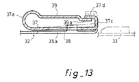
- La figure 13 est une vue de détail du pontet supportant la patte flexible, dans le cas d'une première variante de réalisation par rapport à la figure 9b.
- La figure 14 est une vue de détail du pontet supportant la patte flexible, dans le cas d'une deuxième variante de réalisation par rapport à la figure 9b.
- La figure 15 est une vue suivant la flèche F₂ de la figure 14.
- La figure 16 est une vue du pontet représenté sur la figure 14, après emmanchement des deux tubes.
- Figure 1a and 1b are schematic axial sectional views of the ends, arranged according to the invention, two pipes prior to fitting.
- Figure 2 is a view similar to the previous after fitting the tubes.
- Figure 3 is a cross section along III - III of Figure 1 a .
- Figure 4 is a cross section along IV - IV of Figure 1 b .
- FIG. 5 a and FIG. 5 b are views, partially in axial section, of the ends fitted according to the invention, of two tubes before their fitting, in the case of a first advantageous alternative embodiment.
- Figure 6a and Figure 6b are partial views, according to the arrows F of arrangements shown in Figures 5 a and 5 b.
- Figure 7 is a view similar to Figures 5 and 5b after assembly of the tubes.
- FIG. 8 is a partial view of the locking device, along the arrow F₁ in FIG. 7.
- FIG. 9 a and FIG. 9 b are partial views in axial section, of the ends arranged according to the invention, of two tubes before their fitting, in the case of the second advantageous variant of embodiment.
- FIG. 10 a and FIG. 10 b are partial views, along the arrows F ′ , of the arrangements shown in FIGS. 9 a and 9 b .
- Figure 11 is a view similar to Figures 9 a and 9 b after fitting the tubes.
- FIG. 12 is a partial view of the locking device, along the arrow F₁ ′ in FIG. 11.
- FIG. 13 is a detailed view of the trigger guard supporting the flexible tab, in the case of a first alternative embodiment with respect to FIG. 9 b .
- FIG. 14 is a detailed view of the trigger guard supporting the flexible tab, in the case of a second alternative form of embodiment relative to FIG. 9 b .
- FIG. 15 is a view along the arrow F₂ in FIG. 14.
- Figure 16 is a view of the trigger guard shown in Figure 14, after fitting of the two tubes.
Si l'on se reporte tout d'abord aux figures 1 à 4 on voit un tube interne 1 destiné à être emmanché dans un tube externe 2 pour constituer un ensemble de deux tubes coaxiaux. Le diamètre intérieur du tube 2 est sensiblement égal au diamètre extérieur du tube 1. Les parois de ces deux tubes ont été représentées avec une épaisseur relativement importante pour faciliter les explications des aménagements prévus à leurs extrémités en regard, mais il est évident, ainsi que cela sera souligné ultérieurement, que l'invention n'impose aucune exigence particulière à cet égard.If we refer first to Figures 1 to 4 we see a
Sur la face extérieure 1a du tube 1 sont disposés un bossage 3 et une protubérance 4, par exemple diamétralement opposée au bossage 3.On the
Le bossage 3 présente une forme généralement allongée dans le sens axial du tube 1 et ses faces latérales 3a et 3b sont parallèles à l'axe du tube et font saillie d'une hauteur h par rapport à la surface extérieure 1a . La protubérance 4, généralement de dimensions moins importante que le bossage 3, peut présenter une forme sensiblement carrée, l'une au moins de ses extrémités axiales 4a et 4b , et notamment l'extrémité 4a la plus éloignée de l'extrémité 1b du tube, étant située dans un plan transversal du tube 1, de façon à constituer un épaulement transversal.The
On notera que la zone 4b de la protubérance 4, la plus proche axialement de l'extrémité 1a du tube, est cependant plus éloignée de cette extrémité que la zone correspondante 3c du bossage 3. Les raisons de cette disposition apparaîtront plus loin.It will be noted that the zone 4 b of the
Sur la face intérieure du tube externe 2 est ménagée une rainure 5 dont les bords latéraux 5a et 5b sont parallèles à l'axe du tube et sont espacés l'un de l'autre d'une distance e sensiblement égale à celle séparant les faces latérales opposées 3a et 3b du bossage 3. La profondeur de la rainure est au moins égale à la saillie radiale h des faces latérales 3a et 3b .On the inner face of the
La rainure 5 débouche à l'extrémité 2a du tube 2 et sa longueur axiale est, de préférence, au moins égale à celle du bossage 3. Elle est déterminée par une face terminale 5c dont la position sera précisée plus loin.The
Diamétralement opposée à la rainure 5 et logée dans un évidemment 6 de la paroi du tube 2, se trouve une patte longitudinale 7. A l'état libre et comme représenté sur la figure 1b, la face interne de la patte 7 coïncide sensiblement avec la surface cylindrique interne de la paroi du tube 2.Diametrically opposite to groove 5 and housed in a obviously 6 of the wall of the
La patte 7 est fixée, au voisinage de son extrémité interne 7a , à la paroi du tube 2 et son extrémité externe 7b est située sensiblement dans le plan transversal de l'extrémité 2a du tube 2, de préférence à l'intérieur du tube. La forme de la patte 7 et/ou ses moyens de fixation à la paroi du tube la rendent élastiquement flexible ou mobile, autour d'un axe transversal situé au voisinage de son extrémité interne 7a , à l'intérieur de l'évidement 6.The
Au voisinage de son extrémité externe 7b , la patte 7 présente un logement 8, par exemple de forme sensiblement identique à celle de la protubérance 4. On soulignera ici que le logement 8 peut être constitué par un trou traversant l'épaisseur de la patte. Dans l'exemple représenté, la profondeur du logement 8 est sensiblement égale à la saillie radiale de la protubérance 4 par rapport à la surface extérieure 1a du tube 1. L'une au moins des extrémités longitudinales 8a et 8b du logement 8, notamment l'extrémité 8a voisine de l'extrémité 7b de la patte 7, est située dans un plan transversal du tube 1, perpendiculaire à sa surface intérieure. La distance axiale entre les deux extrémités 8a et 8b est, de préférence, sensiblement égale à celle qui sépare les deux extrémités axiales 4a et 4b de la protubérance 4.In the vicinity of its
L'homme de métier a déjà compris le fonctionnement du dispositif de verrouillage qui vient d'être décrit. L'extrémité libre 1b est tout d'abord emmanchée dans l'extrémité libre 2a , quelle que soit l'orientation relative du bossage 3 et de la protubérance 4, de la rainure 5 et de la patte 7.Those skilled in the art have already understood the operation of the locking device which has just been described. The
Lorsque le bossage 3 vient en appui sur l'extrémité du tube 2, le mouvement d'emmanchement ne peut être poursuivi qu'après mise en coïncidence du bossage 3 et de l'ouverture terminale de la rainure 5. L'orientation relative du tube externe et du tube interne est alors fixée et la protubérance 4 se trouve nécessairement dans l'alignement de la patte 7.When the
Le mouvement d'emmanchement se poursuit, les faces latérales 3a et 3b du bossage étant guidées par les bords latéraux 5a et 5b de la rainure. L'extrémité 7b de la patte 7 est soulevée par la protubérance 4 et la patte 7, dans son ensemble, est repoussée élastiquement dans l'évidement 6. Lorsque la protubérance 4 se trouve en regard du logement 8, la patte 7 revient à sa position initiale, le logement 8 coiffant et emprisonnant cette protubérance. Si, comme on l'a indiqué plus haut, les extrémités axiales 4a et 4b de la protubérance 8a et 8b du logement sont perpendiculaires aux surfaces extérieures ou intérieures des tubes, elles constituent des zones complémentaires d'appui axial, assurant l'immobilisation axiale des deux tubes l'un par rapport à l'autre, aussi bien dans le sens de l'emmanchement que dans celui du déboîtement.The fitting movement continues, the lateral faces 3 a and 3 b of the boss being guided by the
On pourrait toutefois concevoir que seules les extrémités axiales 4a et 8a soient conformées de façon à constituer des zones complémentaires d'appui axial, assurant l'immobilisation dans le sens du déboîtement. Dans ce cas pour limiter l'emmanchement des deux tubes l'un dans l'autre, on pourrait utiliser d'autres moyens. En particulier, la longueur de la rainure 5 pourrait être déterminée de façon que son extrémité 5a constitue une zone d'appui axial pour l'extrémité longitudinale antérieure 3c du bossage 3, après que l'épaulement 4a a atteint ou même légèrement dépassé l'extrémité 8a du logement 8.It could however be conceived that only the axial ends 4 a and 8 a are shaped so as to constitute complementary zones of axial support, ensuring immobilization in the direction of disengagement. In this case, to limit the fitting of the two tubes into one another, other means could be used. In particular, the length of the
Une telle disposition permet de réaliser la protubérance 4 sous forme d'une simple rampe pour l'extrémité 7b de la patte 7.Such an arrangement allows the
Si l'on se reporte maintenant aux figures 5 à 8 on voit une variante avantageuse de réalisation qui peut être associée à un dispositif de raccordement d'un tuyau souple sur un embout tubulaire rigide tel que celui qui fait l'objet de la demande de brevet précitée. Les éléments déjà décrits portent les mêmes références augmentées de 10. L'une des principales différences entre les deux réalisations est que le tube externe est constitué par une tôle métallique mince qui, par conséquent, peut être facilement découpée et éventuellement formée par emboutissage.If we now refer to Figures 5 to 8 we see an advantageous alternative embodiment which can be associated with a device for connecting a flexible pipe to a rigid tubular end piece such as that which is the subject of the request for aforementioned patent. The elements already described have the same references increased by 10. One of the main differences between the two embodiments is that the outer tube is constituted by a thin metal sheet which, therefore, can be easily cut out. and possibly formed by stamping.
Ainsi qu'on le voit sur les figures, le tube externe 12 est un appendice en tôle mince, fixé à l'extrémité d'un tuyau souple dans les conditions exposées dans la demande de brevet précitée. Il est destiné à être emmanché sur un embout rigide ou tube interne 11, généralement en matière plastique. Sur la surface extérieure 11a on retrouve la protubérance 14 qui est toutefois associée à deux bossages 13-13′ disposés symétriquement l'un de l'autre par rapport au plan diamétral passant par la protubérance 14. On notera cependant qu'à l'ensemble des deux bossages 13-13′ correspond une distance e₁ entre leurs faces latérales opposées 13b -13′a . D'autre part, on retrouve la particularité, signalée plus haut, selon laquelle la zone 14b de la protubérance 14, la plus proche de l'extrémité 11b du tube 11, est plus éloignée de cette extrémité que les zones correspondantes 13c des bossages 13. L'épaulement transversal 14a est sensiblement perpendiculaire à la surface extérieure 11a du tube, cependant que l'extrémité opposée 14b de la protubérance est de préférence constituée par une rampe inclinée.As can be seen in the figures, the
Le tube externe 12 présente une rainure longitudinale 15 dont les deux bords latéraux 15a -15b sont espacés d'une distance e₁ sensiblement égale à celle séparant les faces latérales opposées 13b -13′a des bossages 13-13′.The
Entre les bords 15a -15b de la rainure s'étend une patte longitudinale 17 dont l'extrémité libre 17b est légèrement courbée vers l'extérieur. La patte 17 est obtenue par un découpage convenable de la paroi du tube externe 12 à laquelle elle reste fixée par son extrémité 17a , de préférence de plus faible largeur, qui constitue une zone élastique de pliage. A l'état libre, et comme on le voit sur la figure 5b , la patte 17 est située sur la périphérie du tube 12.Between the
Les bords longitudinaux 17c de la patte 17 sont parallèles aux bords 15a -15b de la rainure et définissent avec eux deux rainures secondaires 15d dont la largeur est voisine de celle de chacun des bossages 13-13′.The longitudinal edges 17 c of the
Enfin la patte 17 présente dans sa partie centrale un trou 18 dont la forme correspond de préférence à celle de la protubérance 14. Plus précisément le bord transversal 18a est perpendiculaire aux bords 15a -15b de la rainure.Finally, the
La mise en place du dispositif de verrouillage est analogue à celle qui a été décrite plus haut. L'emmanchement complet du tube 12 sur le tube 11 nécessitera évidemment la présentation correcte des bords 15a -15b de la rainure 15 dans l'alignement des faces latérales opposées 13b -13′a des bossages 13-13′ (position représentée en trait ponctué sur la figure 6b). A cet effet, et notamment dans le cas d'un emmanchement automatisé au moyen d'un robot, il sera avantageusement prévu, sur un élément lié au tube 12, un organe d'indexage approprié désigné par la référence A. La poursuite de l'emmanchement provoquera d'abord la coopération des surfaces de guidage 13b -13′a avec les bords latéraux 15a -15b de la rainure, puis le soulèvement de la patte 17, par la coopération de son extrémité 17b avec la rampe 14b de la protubérance 14. Le verrouillage est terminé lorsque le bord transversal 18a du trou 18 est venu prendre appui derrière l'épaulement transversal 14a de la protubérance 14, la patte 17 étant alors ramenée élastiquement à son état libre (figures 7 et 8).The positioning of the locking device is similar to that which has been described above. The complete fitting of the
L'immobilisation en rotation des deux tubes 11 et 12 est assurée par la coopération des bords 15a -15b de la rainure 15 et des faces latérales 13b -13′a des bossages 13-13′, cependant que l'immobilisation axiale au déboîtement est obtenue par l'appui mutuel du bord 18a du trou 18 et de l'épaulement 14a de la protubérance 14.The immobilization in rotation of the two
L'immobilisation axiale dans le sens de l'emmanchement peut être obtenue par l'appui des bossages 13-13′ sur le fond 15c de la rainure 15 ou par tout autre appui convenable du tube 11 sur une butée liée au tube 12, telle que celle indiquée en B sur la figure 7.Axial immobilization in the fitting direction can be obtained by pressing the bosses 13 - 13 ′ on the bottom 15 c of the
Si l'on se reporte maintenant aux figures 9 à 12, on voit une deuxième variante de réalisation, analogue à celle qui vient d'être décrite en référence aux figures 5 à 8. Comme la précédente, elle sera avantageusement associée à un dispositif de raccordement d'un tuyau souple sur un embout rigide tel que celui qui fait l'objet de la demande de brevet précitée. Les éléments déjà décrits portent les mêmes références, à nouveau augmentées de 10. De même que dans la variante précédente, le tube externe est constitué par une tôle métallique mince, qui peut être facilement découpée et emboutie.If we now refer to FIGS. 9 to 12, we see a second variant embodiment, similar to that which has just been described with reference to FIGS. 5 to 8. Like the previous one, it will advantageously be associated with a device for connecting a flexible pipe to a rigid end piece such as that which is the subject of the aforementioned patent application. The elements already described have the same references, again increased by 10. As in the previous variant, the outer tube consists of a thin metal sheet, which can be easily cut and stamped.
Sur la surface extérieure 21a de l'embout rigide 21, qui constitue le tube interne, on retrouve deux bossages allongés 23 et 23′ dont les faces latérales opposées 23b -23′a font radialement saillie et sont parallèles à l'axe du tube, étant espacées l'une de l'autre d'une distance transversale e′₁. Les extrémités longitudinales de ces bossages sont situées dans deux plans transversaux du tube, de préférence, comme représenté au dessin, dans le même plan transversal pour chaque couple d'extrémités correspondantes. Les extrémités 23c et 23′c , les plus proches de l'extrémité 21b du tube, présentent avantageusement une forme de rampe, tandis que les extrémités 24a et 24′a constituent des épaulements faisant radialement saillie par rapport à la surface extérieure 21a du tube. Bien que les bossages 23 et 23′ puissent n'en constituer qu'un seul, ils seront de préférence distincts l'un de l'autre, leurs faces latérales 23a et 23′b étant séparées par une petite distance de façon à ménager une encoche longitudinale 21d dont l'utilité apparaîtra plus loin.On the outer surface 21 a of the
Le tube externe 22 présente une rainure longitudinale 25 dont les bords longitudinaux 25a -25b sont parallèles à l'axe du tube et sont espacés d'une distance sensiblement égale à celle séparant les faces latérales opposées 23b -23′a des bossages 23-23′. De préférence, et comme on le voit bien sur les figures 9b et 10b, les bords 25a et 25b de la rainure sont munis de petites pattes 25c et 25d perpendiculaires au plan de la rainure et améliorant, ainsi qu'on le précisera plus loin, le rôle de guidage des bords de la rainure.The
Un pontet 29 supportant la patte longitudinale flexible 27 est fixé au tube externe 22 au dessus de la rainure 25. Ce pontet, de préférence en acier à ressort, comporte sur chacun de ses bords latéraux un repli 29a dont l'extrémité gauche, légèrement coudée, prend appui (fig. 9b) sur une protubérance 22a liée au tube 22 tandis que son extrémité droite est simplement sertie sur le bord terminal 22b , replié vers l'arrière, du tube 22 (fig. 10b).A
La patte 27 est constituée par un repli de la face supérieure du pontet 29 se raccordant à elle par une boucle 27a , bien visible en coupe sur la figure 9b. Elle présente une largeur sensiblement plus grande que celle de la rainure 25 ainsi qu'on le voit sur la figure 10b. A son extrémité libre, située sensiblement dans le plan transversal du bord terminal 22b du tube, la patte 27 comporte un crochet 27c replié sur la face supérieure du pontet 29.The
La patte 27 présente deux ouvertures 28 et 28′ dont le contour correspond à celui des bossages 23 et 23′. En particulier les bords transversaux 28 et 28′a , les plus proches du bord terminal 22b du tube externe, sont, de préférence, dans le même plan transversal, cependant que les bords longitudinaux opposés 28b et 28′b sont avantageusement décalés latéralement par rapport aux bords 25a -25b de la rainure, permettant ainsi le passage des pattes 25c et 25d dans les ouvertures 28 et 28′.The
Dans l'exemple représenté, il subsiste une languette métallique 27d dont la largeur correspond à celle de l'encoche 21d entre les bossages 23-23′ et qui participe à la résistance mécanique du bord transversal terminal de la patte 27. Il est toutefois évident que si les bossages 23-23′ n'en constituent qu'un seul, il en sera de même des ouvertures 28-28′.In the example shown, there remains a metal tongue 27 d whose width corresponds to that of the notch 21 d between the bosses 23 - 23 ′ and which contributes to the mechanical strength of the terminal transverse edge of the
A l'état libre, la patte 27 repose sur les bords longitudinaux de la rainure 25 et y est élastiquement maintenue par le ressort que constitue la boucle 27a .In the free state, the
La mise en place du dispositif de verrouillage est analogue à celle qui a été décrite plus haut. Après une présentation correcte des bossages 23-23′ en regard de l'ouverture de la rainure 25 (position représentée en trait ponctué sur la figure 10b), l'emmanchement du tube 21 dans le tube 22 provoque d'abord le soulèvement de la patte 27 par les rampes 23c -23′c des bossages. Les faces latérales 23b -23′a de ces derniers sont guidées longitudinalement par les bords 25a -25b de la rainure et surtout par leurs petites pattes 25c -25d . A la fin de l'emmanchement, les bords transversaux 28a -28′a des ouvertures de la patte 27 viennent en appui axial derrière les épaulements 24a -24′a des bossages 23-23′, cependant que la patte 27 reprend la position qu'elle occupait à l'état libre sous l'effet de son ressort 27a (fig. 11).The positioning of the locking device is similar to that which has been described above. After a correct presentation of the bosses 23 - 23 ′ opposite the opening of the groove 25 (position shown in dotted line in FIG. 10 b ), the fitting of the
Les deux tubes sont alors immobilisés axialement et en rotation, tant vis-à-vis du déboîtement que dans le sens de l'emmanchement. A cet égard les dispositions décrites plus haut, seront, ici encore, utilisables.The two tubes are then immobilized axially and in rotation, both with respect to the disengagement and in the direction of fitting. In this regard, the arrangements described above will again be usable.
Quel que soit le mode de réalisation envisagé, il sera généralement intéressant de prévoir des moyens permettant le contrôle visuel et facile du bon verrouillage des deux tubes, c'est-à-dire du retour de la patte de verrouillage à sa position à l'état libre, après coopération des ouvertures de la patte et de l'épaulement prévu en correspondance sur la surface extérieure du tube interne.Whatever the embodiment envisaged, it will generally be advantageous to provide means allowing visual and easy control of the correct locking of the two tubes, that is to say of the return of the locking tab to its position at the free state, after cooperation of the openings of the tab and the shoulder provided in correspondence on the external surface of the internal tube.
A cet effet et si l'on se reporte maintenant à la figure 13 on voit une variante avantageuse du pontet recouvrant la rainure du tube externe et représenté aux figures 9b et 10b. Les éléments déjà décrits portent les mêmes numéros de référence augmentés à nouveau de 10.To this end and if we now refer to Figure 13 we see an advantageous variant of the trigger guard covering the groove of the outer tube and shown in Figures 9b and 10b . The elements already described bear the same reference numbers increased again by 10.
Comme on l'a déjà indiqué, le pontet 39 est disposé au dessus de la rainure longitudinale ménagée dans le tube externe 32 et la patte 37 est constituée par un repli raccordé au pontet par la boucle 37a . Du côté de l'entrée de la rainure, située à droite de la figure 13, la patte 37 se termine par un crochet 37c replié au dessus de la face supérieure du pontet.As already indicated, the
Cette dernière présente un embrèvement 39a dont la profondeur correspond sensiblement à l'épaisseur de la tôle et dont la largeur (dans le sens perpendiculaire à la figure) est avantageusement voisine de celle du crochet 37c . Celui-ci possède un repli 37d dont le plan est parallèle à celui de la patte 37.The latter has a recess 39 a whose depth corresponds substantially to the thickness of the sheet and whose width (in the direction perpendicular to the figure) is advantageously close to that of the
Au cours de l'emmanchement des tubes le bossage 33 soulève la patte 37 et son repli 37d fait saillie au dessus de la face supérieure du pontet 39 (position en trait ponctué). Après avoir été guidé par le bord longitudinal 35a de la rainure, le bossage 33 vient en regard de l'ouverture 38 de la patte 37. Sous l'effet de son ressort 37a , la patte 37 reprend la position représentée en trait plein sur la figure, ce qui assure le verrouillage.During the fitting of the tubes, the
Si pour une raison quelconque l'emmanchement des tubes n'est pas suffisant pour provoquer leur verrouillage, la patte 37 et son repli 37d sont maintenus dans la position représentée en trait ponctué, ce qui sera facilement décelé par l'opérateur, au moyen d'un simple contrôle visuel.If for some reason the fitting of the tubes is not sufficient to cause their locking, the
Si l'on se reporte enfin aux figures 14 à 16 on voit une autre variante des moyens permettant le contrôle visuel du verrouillage. Les éléments déjà décrits et représentés sur les figures 9b et 10b portent les mêmes références augmentées de 20.If we finally refer to Figures 14 to 16 we see another variant of the means for visual inspection of the locking. The elements already described and represented in FIGS. 9 b and 10 b bear the same references increased by 20.
Le pontet 49 disposé au dessus de la rainure du tube externe 42 supporte la patte 47 par l'intermédiaire de la boucle 47a formant ressort. On notera cependant que la patte 47 présente un décrochement 47b dont l'utilité apparaîtra plus loin, cependant que son crochet terminal 47c est situé en deçà du bord terminal 49b du pontet 49.The
Un cavalier 51 en matériau élastique, de préférence en acier à ressort, est constitué par une feuille pliée en forme de U entourant le pontet 49 et sa patte 47. Le fond du U est situé dans la zone de la boucle 47a et présente un évidement 51a , bien visible sur la figure 15, permettant le passage de la boucle 47a .A
La branche inférieure 51b du cavalier est située au dessous de la patte 47 et s'étend en deçà du décrochement 47b de la patte. La branche supérieure 51c du cavalier s'étend au dessus de la face supérieure du pontet 49. Dans sa partie centrale cette branche supérieure 51c est susceptible d'être en prise (figures 14 et 15) avec le repli terminal 47e du crochet 47c de la patte 47, cependant que, de part et d'autre de cette partie centrale, elle se prolonge par des crochets 51d dirigés vers la branche inférieure 51b .The
Ainsi le cavalier 51 qui vient d'être décrit constitue un organe monté coulissant axialement par rapport au pontet 49 et à sa patte 47 et susceptible d'être en prise avec un élément de cette dernière. De plus, pour des raisons que l'on précisera plus loin, il faut ici noter qu'à l'état libre (non représenté) les branches 51b -51c du cavalier 51 sont légèrement divergentes, de sorte qu'elles subissent une déformation élastique lorsqu'elles sont disposées parallèles l'une à l'autre (figure 14). Le cavalier 51 constitue aussi un ressort qui tend à écarter l'une de l'autre les extrémités de ses branches 51b et 51c .Thus the
La branche inférieure 51b du cavalier présente cependant, ainsi qu'on le voit sur la figure 15, un bord terminal 51e comportant, au dessous des ouvertures 48-48′ de la patte 47, deux saillies longitudinales 51f et 51g , plus proches de l'extrémité du tube externe 42 que ne l'est le reste du bord 51e .However, as can be seen in FIG. 15, the
Avant l'emmanchement des tubes 41 et 42, le cavalier 51 est dans la position représentée sur la figure 14, et la partie centrale terminale de sa branche supérieure 51c s'appuie sous le repli terminal 47e de la patte 47. Celle-ci est donc soulevée, contre le ressort constitué par sa boucle 47a , au dessus de la rainure 45, cependant que la branche supérieure 51c du cavalier est appliquée sur la face supérieure du pontet 49 et que le ressort constitué par le cavalier lui-même est comprimé.Before the fitting of the
Lorsque les bossages 43-43′ sont engagés dans la rainure 45 ils soulèvent encore, si nécessaire, la patte 47 et leur face frontale 43c -43′c vient en contact avec les saillies 51f -51g de la branche inférieure 51b du cavalier 51. L'emmanchement des tubes se poursuivant, les bossages font coulisser la branche inférieure 51b dans le sens de la flèche f jusqu'à la position représentée sur la figure 16. La partie centrale terminale de la branche supérieure 51c quitte alors son appui sous le repli 47e , ce qui libère la patte 47 qui vient donc occuper sa position de verrouillage du tube 41 dans les conditions déjà décrites.When the bosses 43 - 43 ′ are engaged in the
Simultanément la branche supérieure 51c du cavalier se détend élastiquement en prenant une position divergente par rapport à la branche inférieure 51b . Ce mouvement reste néanmoins limité grâce à la présence des crochets latéraux 51d qui viennent prendre appui sous le pontet 49. Cette position du cavalier 51 permet un contrôle visuel et facile du verrouillage par l'opérateur.Simultaneously the
En outre on peut, dans le même but, prévoir un repère coloré sur la partie centrale terminale de la branche supérieure 51c du cavalier, dans la zone susceptible d'être recouverte par le repli terminal 47e de la patte 47. Ce repère ne devient donc visible qu'après que la patte 47 est arrivée dans sa position de verrouillage.In addition, it is possible, for the same purpose, to provide a colored mark on the central central part of the
La variante qui vient d'être décrite présente un avantage supplémentaire important par rapport à celle représentée sur la figure 13.The variant which has just been described has an important additional advantage compared to that shown in FIG. 13.
Il peut en effet se produire des défauts de fabrication des bossages prévus sur le tube interne 41, notamment si ce dernier est réalisé par moulage en matière plastique. Il importe alors que l'emmanchement des tubes ne puisse être poursuivi jusqu'à sa phase terminale et que l'attention de l'opérateur soit rapidement attirée par ce défaut.It can indeed occur manufacturing defects of the bosses provided on the
Si l'on suppose, par exemple, que le(s) bossage(s) 43-43′ n'existe(nt) pas, l'appui simultané des faces frontales 43c -43′c sur les saillies 51f -51g ne se produira pas. Dans ce cas, le cavalier 51 ne coulissera pas normalement, de la façon décrite plus haut, ce qui empêchera la partie centrale terminale de la branche 51c de se dégager du repli terminal 47e . L'opérateur sera donc immédiatement averti de l'anomalie par un simple contrôle visuel.If it is assumed, for example, that the boss (s) 43 - 43 ′ does not exist, the simultaneous pressing of the front faces 43 c - 43 ′ c on the
De plus, si seulement l'une des saillie 51f -51g est atteinte par le(s) bossage(s), le cavalier 51 pivotera au lieu de coulisser, interdisant là encore le dégagement des éléments 51c et 47e et attirant de ce fait l'attention de l'opérateur.In addition, if only one of the
Ainsi que l'homme de métier s'en est rendu compte, les dispositions proposées par l'invention peuvent être réalisées de façon très économique, malgré le grand nombre d'avantages qu'elles procurent. En particulier la sécurité de montage et de fonctionnement sera spécialement utile et appréciée dans le cas où l'emmanchement des tubes interne et externe est obtenu par des appareils automatisés.As those skilled in the art have realized, the arrangements proposed by the invention can be carried out very economically, despite the large number of advantages which they provide. In particular, the mounting and operating safety will be especially useful and appreciated in the case where the fitting of the internal and external tubes is obtained by automated devices.
Claims (15)
- Device for locking two coaxial tubes designed to be fitted into each other, comprising a longitudinal tab which is elastically flexible in the radial direction, connected to the outer tube and presenting at least one area capable of coming into axial abutment, once the two tubes have been fitted together, with a shoulder provided in register on the outer face of the inner tube and projecting radially with respect therefrom, characterized in that the wall of the outer tube (2, 12, 22) presents a groove (5, 15, 25) open at the end of the tube, whose lateral edges are parallel to the axis of the tube, and in that the outer face of the inner tube (1, 11, 21) presents two radially projecting guide surfaces (3a-3b, 13′a, 23b-23′a), said surfaces being parallel to the axis of the tube and spaced apart from each other by a distance substantially equal to the one separating the lateral edges of the groove of the outer tube, while the free end of the locking tab (7, 17, 27) is located substantially in the transverse plane of the end of the outer tube.
- Device according to claim 1, characterized in that the flexible tab (17, 27) is made of metal and is located substantially opposite the longitudinal groove (15, 25) of the outer tube, and in that its longitudinal diametral plane of symmetry is the same as that of said groove.
- Device according to claim 1, characterized in that the guide surfaces (3a-3b, 13b-13′a, 23b-23′a) provided on the inner tube are constituted by the lateral faces, opposite one another, of at least one elongated boss (3, 13-13′, 23-23′) projecting radially on the outer face of the inner tube.
- Device according to claim 3, characterized in that there exist two bosses (13-13′, 23-23′) symmetrical to each other with respect to a longitudinal diametral plane of the inner tube.
- Device according to claim 4, characterized in that the area (13c, 13′c) of the bosses (13, 13′) closest to the fitted end (11b) of the inner tube, is closer to said end than the corresponding area (14b) of the axial locking shoulder.
- Device according to claims 2 and 5, characterized in that, over at least a part of its length, each lateral edge (17c) of the flexible tab (17) is spaced from the adjacent lateral edge (15a-15b) of the groove (15) by a distance substantially equal to the transverse thickness of each boss (13-13′).
- Device according to claim 6, characterized in that the tab (17) presents an opening (18) whose contour is substantially identical to that of the shoulder (14).
- Device according to any one of the preceding claims, characterized in that the outer tube (12) being made of thin sheet metal, its longitudinal groove (15) as well as its tab (17) are obtained by a cut-out of its wall, so that said tab constitutes an elastically flexible element of the wall itself of the outer tube.
- Device according to claim 3, characterized in that the area (24a) of the boss (23) most remote from the fitted end (22b) of the inner tube constitutes the axial locking shoulder.
- Device according to claim 3, characterized in that the flexible tab (27) is made of metal and presents at least one opening (28) whose contour is substantially identical to that of boss (23).
- Device according to claim 4 and claim 10, characterized in that the two openings (28-28′) of the flexible tab (27) are separated by a tongue (21d) whose width corresponds substantially to the distance between the two opposite longitudinal faces (23a-23′b) of the two bosses (23-23′).
- Device according to any one of claims 9, 10, and 11, characterized in that the flexible tab (27) is constituted by the fold of a metal bridge (29) fixed, preferably by crimping, to the end of the outer tube.
- Device according to claim 12, characterized in that, in the position of locking of the flexible tab (47), its free end, preferably in the form of a hook (37d), is located in a housing (39a) provided in register in the upper face of the bridge (39).
- Device according to claim 12, characterized in that a member (51) forming spring and mobile with respect to the bridge (49) is coupled, in a first position, to the flexible tab (47) before the tubes are fitted together, said member being capable of occupying a position visually different from the first, when the flexible tab is in its axial locking position after the tubes have been fitted together.
- Device according to claim 14, characterized in that the member mobile with respect to the bridge is constituted by an elastic slide (51) whose section is in the form of a U and of which one of the arms (51c) is in abutment on a hook (47c) fast with the tab (47), as long as the latter is not in its axial locking position.
Priority Applications (1)
| Application Number | Priority Date | Filing Date | Title |
|---|---|---|---|
| AT91400242T ATE81900T1 (en) | 1990-02-02 | 1991-02-01 | DEVICE FOR COUPLING TWO COAXIAL PIPES. |
Applications Claiming Priority (2)
| Application Number | Priority Date | Filing Date | Title |
|---|---|---|---|
| FR9001260 | 1990-02-02 | ||
| FR9001260 | 1990-02-02 |
Publications (2)
| Publication Number | Publication Date |
|---|---|
| EP0443895A1 EP0443895A1 (en) | 1991-08-28 |
| EP0443895B1 true EP0443895B1 (en) | 1992-10-28 |
Family
ID=9393361
Family Applications (1)
| Application Number | Title | Priority Date | Filing Date |
|---|---|---|---|
| EP91400242A Expired - Lifetime EP0443895B1 (en) | 1990-02-02 | 1991-02-01 | Coupling device for two coaxial tubes |
Country Status (12)
| Country | Link |
|---|---|
| US (1) | US5249830A (en) |
| EP (1) | EP0443895B1 (en) |
| JP (1) | JPH04504752A (en) |
| AT (1) | ATE81900T1 (en) |
| BR (1) | BR9105811A (en) |
| CA (1) | CA2065236A1 (en) |
| DE (1) | DE69100007T2 (en) |
| DK (1) | DK0443895T3 (en) |
| ES (1) | ES2036116T3 (en) |
| GR (1) | GR3006603T3 (en) |
| HU (1) | HU211404B (en) |
| WO (1) | WO1991011650A1 (en) |
Families Citing this family (11)
| Publication number | Priority date | Publication date | Assignee | Title |
|---|---|---|---|---|
| DE4416311A1 (en) * | 1994-05-09 | 1995-11-16 | Itw Oberflaechentechnik Gmbh | Sprayer attachment device |
| US5651303A (en) * | 1994-11-14 | 1997-07-29 | Polygon Company | Fluid cylinder end cap assembly |
| US5465647A (en) * | 1994-11-14 | 1995-11-14 | Polygon Company | Fluid cylinder end cap assembly |
| US5716081A (en) * | 1996-03-11 | 1998-02-10 | Automotive Products (Usa), Inc. | Spring clip for quick connect coupling |
| US6032328A (en) * | 1998-02-10 | 2000-03-07 | Rexair, Inc. | Crevice cleaning tool for a vacuum cleaner apparatus |
| US6367974B1 (en) * | 1999-04-19 | 2002-04-09 | Peter Lin | Thermocouple apparatus and well for containers having a flanged access opening |
| US7490620B2 (en) * | 2004-02-23 | 2009-02-17 | Tyco Healthcare Group Lp | Fluid conduit connector apparatus |
| US7871387B2 (en) | 2004-02-23 | 2011-01-18 | Tyco Healthcare Group Lp | Compression sleeve convertible in length |
| US7967342B2 (en) * | 2005-03-01 | 2011-06-28 | Ti Group Automotive Systems, Llc | Anti-rotation quick connector |
| US8257286B2 (en) | 2006-09-21 | 2012-09-04 | Tyco Healthcare Group Lp | Safety connector apparatus |
| US8257287B2 (en) * | 2008-03-20 | 2012-09-04 | Tyco Healthcare Group Lp | Safety connector assembly |
Family Cites Families (16)
| Publication number | Priority date | Publication date | Assignee | Title |
|---|---|---|---|---|
| US753096A (en) * | 1904-02-23 | Peters xx | ||
| GB190609899A (en) * | 1905-06-27 | 1906-10-25 | Earl Judson Wheler De Foreest | Improvements in and relating to Hose Couplings. |
| US2184881A (en) * | 1937-03-19 | 1939-12-26 | P A Geier Co | Tubular coupling for suction cleaners and the like |
| US2789839A (en) * | 1952-08-27 | 1957-04-23 | Bissell Carpet Sweeper Co | Spring detent engaging means for carpet sweeper sectional handle |
| BE635043A (en) * | 1962-07-16 | |||
| US3245698A (en) * | 1963-11-04 | 1966-04-12 | Westinghouse Electric Corp | Latching means |
| US3244437A (en) * | 1964-01-28 | 1966-04-05 | Electrolux Corp | Adjustable length vacuum cleaner wand |
| SE7416373L (en) * | 1974-01-10 | 1975-07-11 | Eric G Doubleday | |
| US3933378A (en) * | 1974-11-29 | 1976-01-20 | Ford Motor Company | Quick-connect tubing coupling |
| DE2921607C2 (en) * | 1979-05-28 | 1981-10-08 | Ford-Werke AG, 5000 Köln | Plug connection for hose lines, in particular in motor vehicles |
| US4448470A (en) * | 1981-12-28 | 1984-05-15 | The Bendix Corporation | Coupling member and an electrical connector |
| US4618195A (en) * | 1985-06-03 | 1986-10-21 | Whirlpool Corporation | Vacuum cleaner hose coupling |
| US4915421A (en) * | 1988-03-30 | 1990-04-10 | Itt Corporation | Quick connector assembly |
| DE3815172C1 (en) * | 1988-05-04 | 1990-03-22 | Rasmussen Gmbh, 6457 Maintal, De | |
| US5112084A (en) * | 1989-02-07 | 1992-05-12 | Usui Kokusai Sangyo Kaisha, Ltd. | Connector for small-diameter piping |
| US5104253A (en) * | 1990-06-06 | 1992-04-14 | Chrysler Corporation | Cable assembly, lock therefor |
-
1991
- 1991-02-01 EP EP91400242A patent/EP0443895B1/en not_active Expired - Lifetime
- 1991-02-01 ES ES199191400242T patent/ES2036116T3/en not_active Expired - Lifetime
- 1991-02-01 DK DK91400242.3T patent/DK0443895T3/en active
- 1991-02-01 CA CA002065236A patent/CA2065236A1/en not_active Abandoned
- 1991-02-01 BR BR919105811A patent/BR9105811A/en not_active Application Discontinuation
- 1991-02-01 HU HU9200817A patent/HU211404B/en not_active IP Right Cessation
- 1991-02-01 US US07/768,430 patent/US5249830A/en not_active Expired - Fee Related
- 1991-02-01 WO PCT/FR1991/000066 patent/WO1991011650A1/en active Application Filing
- 1991-02-01 JP JP3503780A patent/JPH04504752A/en active Pending
- 1991-02-01 AT AT91400242T patent/ATE81900T1/en not_active IP Right Cessation
- 1991-02-01 DE DE9191400242T patent/DE69100007T2/en not_active Expired - Fee Related
-
1992
- 1992-12-21 GR GR920403011T patent/GR3006603T3/el unknown
Also Published As
| Publication number | Publication date |
|---|---|
| DK0443895T3 (en) | 1993-02-22 |
| JPH04504752A (en) | 1992-08-20 |
| CA2065236A1 (en) | 1991-08-03 |
| HU211404B (en) | 1995-11-28 |
| ES2036116T3 (en) | 1993-05-01 |
| HU9200817D0 (en) | 1992-08-28 |
| DE69100007T2 (en) | 1993-05-13 |
| EP0443895A1 (en) | 1991-08-28 |
| WO1991011650A1 (en) | 1991-08-08 |
| ATE81900T1 (en) | 1992-11-15 |
| US5249830A (en) | 1993-10-05 |
| GR3006603T3 (en) | 1993-06-30 |
| DE69100007D1 (en) | 1992-12-03 |
| HUT67481A (en) | 1995-04-28 |
| BR9105811A (en) | 1992-08-04 |
Similar Documents
| Publication | Publication Date | Title |
|---|---|---|
| EP0911565B1 (en) | Quick-acting connection between a rigid pipe and a connector | |
| EP0511891B1 (en) | Connector for the quick coupling of a tube | |
| EP0443895B1 (en) | Coupling device for two coaxial tubes | |
| BE898358A (en) | Clamping structure without ear. | |
| FR2569337A1 (en) | CONSTRUCTION OF A RELEASABLE FASTENING FOR USE IN PARTICULAR IN THE FIELD OF PERSONAL JEWELRY | |
| FR2751722A1 (en) | FIXING DEVICE FOR SECURING A TUBE JOINING MEMBER TO A PLATE WHICH IT CROSSES THROUGH AN ASSOCIATED OPENING | |
| FR2473151A1 (en) | PIPE CONNECTION DEVICE | |
| EP0493182A1 (en) | Pipe clamp | |
| FR2857709A1 (en) | CARRIER HAS TWO OPPOSED FINGERS | |
| EP0296919A1 (en) | Clamping collar | |
| FR2685614A1 (en) | LINK STRAP, ESPECIALLY FOR A WATCH. | |
| EP0060748B1 (en) | Holding device, especially for holding a car door in an open position | |
| FR2658899A1 (en) | Device for coupling and automatically locking two coaxial tubes | |
| EP3795878B1 (en) | Clamping collar | |
| EP1423642A1 (en) | Light group for vehicle headlight | |
| FR2540198A1 (en) | AXIS PUSH FASTENING CLAMP FOR BOLT THROUGH A STRUCTURAL ELEMENT | |
| FR2662488A1 (en) | TIGHTENING COLLAR WITH CAPACITY RESERVE. | |
| EP0437639B1 (en) | Seal for the connection of two parts of a conveyor belt and connection comprising such a seal | |
| EP0410842B1 (en) | Quick-acting coupling | |
| EP0603063B1 (en) | One-piece fastening devices for fastening on the serrated head of a shaft | |
| EP0208582B1 (en) | Winding shaft, in particular for a safety belt | |
| WO1998000665A1 (en) | Wire clamping collar | |
| FR2630174A1 (en) | ADJUSTING ASSEMBLY FOR CLUTCH STOP, ESPECIALLY FOR A MOTOR VEHICLE | |
| FR2630070A1 (en) | Windscreen wiper blade including an improved device for connecting a main stirrup piece (clamp) onto a secondary stirrup piece (clamp) | |
| EP1283174B1 (en) | Container with handle and manufacturing method thereof |
Legal Events
| Date | Code | Title | Description |
|---|---|---|---|
| PUAI | Public reference made under article 153(3) epc to a published international application that has entered the european phase |
Free format text: ORIGINAL CODE: 0009012 |
|
| AK | Designated contracting states |
Kind code of ref document: A1 Designated state(s): AT BE CH DE DK ES FR GB GR IT LI LU NL SE |
|
| 17P | Request for examination filed |
Effective date: 19910726 |
|
| 17Q | First examination report despatched |
Effective date: 19920212 |
|
| GRAA | (expected) grant |
Free format text: ORIGINAL CODE: 0009210 |
|
| AK | Designated contracting states |
Kind code of ref document: B1 Designated state(s): AT BE CH DE DK ES FR GB GR IT LI LU NL SE |
|
| REF | Corresponds to: |
Ref document number: 81900 Country of ref document: AT Date of ref document: 19921115 Kind code of ref document: T |
|
| ITF | It: translation for a ep patent filed |
Owner name: JACOBACCI & PERANI S.P.A. |
|
| REF | Corresponds to: |
Ref document number: 69100007 Country of ref document: DE Date of ref document: 19921203 |
|
| GBT | Gb: translation of ep patent filed (gb section 77(6)(a)/1977) |
Effective date: 19930114 |
|
| REG | Reference to a national code |
Ref country code: DK Ref legal event code: T3 |
|
| REG | Reference to a national code |
Ref country code: ES Ref legal event code: FG2A Ref document number: 2036116 Country of ref document: ES Kind code of ref document: T3 |
|
| REG | Reference to a national code |
Ref country code: GR Ref legal event code: FG4A Free format text: 3006603 |
|
| PLBE | No opposition filed within time limit |
Free format text: ORIGINAL CODE: 0009261 |
|
| STAA | Information on the status of an ep patent application or granted ep patent |
Free format text: STATUS: NO OPPOSITION FILED WITHIN TIME LIMIT |
|
| 26N | No opposition filed | ||
| PGFP | Annual fee paid to national office [announced via postgrant information from national office to epo] |
Ref country code: AT Payment date: 19940124 Year of fee payment: 4 |
|
| PGFP | Annual fee paid to national office [announced via postgrant information from national office to epo] |
Ref country code: GR Payment date: 19940127 Year of fee payment: 4 |
|
| PGFP | Annual fee paid to national office [announced via postgrant information from national office to epo] |
Ref country code: ES Payment date: 19940216 Year of fee payment: 4 Ref country code: CH Payment date: 19940216 Year of fee payment: 4 |
|
| PGFP | Annual fee paid to national office [announced via postgrant information from national office to epo] |
Ref country code: SE Payment date: 19940217 Year of fee payment: 4 |
|
| PGFP | Annual fee paid to national office [announced via postgrant information from national office to epo] |
Ref country code: DE Payment date: 19940224 Year of fee payment: 4 |
|
| PGFP | Annual fee paid to national office [announced via postgrant information from national office to epo] |
Ref country code: FR Payment date: 19940225 Year of fee payment: 4 |
|
| PGFP | Annual fee paid to national office [announced via postgrant information from national office to epo] |
Ref country code: NL Payment date: 19940228 Year of fee payment: 4 Ref country code: LU Payment date: 19940228 Year of fee payment: 4 |
|
| PGFP | Annual fee paid to national office [announced via postgrant information from national office to epo] |
Ref country code: BE Payment date: 19940309 Year of fee payment: 4 |
|
| EPTA | Lu: last paid annual fee | ||
| PGFP | Annual fee paid to national office [announced via postgrant information from national office to epo] |
Ref country code: DK Payment date: 19940331 Year of fee payment: 4 |
|
| EAL | Se: european patent in force in sweden |
Ref document number: 91400242.3 |
|
| PG25 | Lapsed in a contracting state [announced via postgrant information from national office to epo] |
Ref country code: LU Free format text: LAPSE BECAUSE OF NON-PAYMENT OF DUE FEES Effective date: 19950201 Ref country code: GB Effective date: 19950201 Ref country code: DK Effective date: 19950201 Ref country code: AT Effective date: 19950201 |
|
| REG | Reference to a national code |
Ref country code: DK Ref legal event code: EBP |
|
| PG25 | Lapsed in a contracting state [announced via postgrant information from national office to epo] |
Ref country code: SE Effective date: 19950202 Ref country code: ES Free format text: LAPSE BECAUSE OF NON-PAYMENT OF DUE FEES Effective date: 19950202 |
|
| PG25 | Lapsed in a contracting state [announced via postgrant information from national office to epo] |
Ref country code: LI Effective date: 19950228 Ref country code: CH Effective date: 19950228 Ref country code: BE Effective date: 19950228 |
|
| BERE | Be: lapsed |
Owner name: ETS CAILLAU Effective date: 19950228 |
|
| PG25 | Lapsed in a contracting state [announced via postgrant information from national office to epo] |
Ref country code: GR Free format text: THE PATENT HAS BEEN ANNULLED BY A DECISION OF A NATIONAL AUTHORITY Effective date: 19950831 |
|
| PG25 | Lapsed in a contracting state [announced via postgrant information from national office to epo] |
Ref country code: NL Effective date: 19950901 |
|
| GBPC | Gb: european patent ceased through non-payment of renewal fee |
Effective date: 19950201 |
|
| PG25 | Lapsed in a contracting state [announced via postgrant information from national office to epo] |
Ref country code: FR Effective date: 19951031 |
|
| REG | Reference to a national code |
Ref country code: GR Ref legal event code: MM2A Free format text: 3006603 |
|
| NLV4 | Nl: lapsed or anulled due to non-payment of the annual fee |
Effective date: 19950901 |
|
| PG25 | Lapsed in a contracting state [announced via postgrant information from national office to epo] |
Ref country code: DE Effective date: 19951101 |
|
| EUG | Se: european patent has lapsed |
Ref document number: 91400242.3 |
|
| REG | Reference to a national code |
Ref country code: FR Ref legal event code: ST |
|
| REG | Reference to a national code |
Ref country code: ES Ref legal event code: FD2A Effective date: 19990503 |
|
| PG25 | Lapsed in a contracting state [announced via postgrant information from national office to epo] |
Ref country code: IT Free format text: LAPSE BECAUSE OF NON-PAYMENT OF DUE FEES;WARNING: LAPSES OF ITALIAN PATENTS WITH EFFECTIVE DATE BEFORE 2007 MAY HAVE OCCURRED AT ANY TIME BEFORE 2007. THE CORRECT EFFECTIVE DATE MAY BE DIFFERENT FROM THE ONE RECORDED. Effective date: 20050201 |