EP0443486B1 - Bildverarbeitungsgerät - Google Patents
Bildverarbeitungsgerät Download PDFInfo
- Publication number
- EP0443486B1 EP0443486B1 EP91102269A EP91102269A EP0443486B1 EP 0443486 B1 EP0443486 B1 EP 0443486B1 EP 91102269 A EP91102269 A EP 91102269A EP 91102269 A EP91102269 A EP 91102269A EP 0443486 B1 EP0443486 B1 EP 0443486B1
- Authority
- EP
- European Patent Office
- Prior art keywords
- output
- threshold value
- conversion
- linear function
- outputs
- Prior art date
- Legal status (The legal status is an assumption and is not a legal conclusion. Google has not performed a legal analysis and makes no representation as to the accuracy of the status listed.)
- Expired - Lifetime
Links
Images





Classifications
-
- G—PHYSICS
- G06—COMPUTING OR CALCULATING; COUNTING
- G06T—IMAGE DATA PROCESSING OR GENERATION, IN GENERAL
- G06T1/00—General purpose image data processing
-
- G—PHYSICS
- G06—COMPUTING OR CALCULATING; COUNTING
- G06T—IMAGE DATA PROCESSING OR GENERATION, IN GENERAL
- G06T5/00—Image enhancement or restoration
- G06T5/20—Image enhancement or restoration using local operators
Definitions
- the present invention relates to a picture processing apparatus using a Laplacian filtering scheme which is one of spatial filtering techniques used for making a defocused image picture sharper.
- Laplacian filtering technique In order to correct these defocused images in a picture, a spatial filtering processing called as Laplacian filtering technique is applied. This technique utilizes the Laplacian components of second derivatives of picture data, and thereby the degradations in the MTF were corrected, so as to sharpen reproduced pictures.
- the spatial filtering processing is carried out by enhancing the data of relevant pixels by utilizing the data of a plurality of reference pixels in the vicinity of those relevant pixels. Namely, an amount of correction is determined from a difference between a datum of the relevant pixel and a sum of data of pixels in the vicinity of the relevant pixel. That is, the amount of correction is determined from the Laplacian component of the second derivatives which expresses the contour lines of the picture image. The correction is achieved by adding this correction value to the data of the relevant pixel.
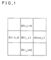
- FIG.1 is a schematic drawing illustrating the conventional spatial filtering scheme.
- D(i,j) represents a datum of a relevant pixel
- D(i+1,j), D(i,j-1), and D(i,j+1) represent data of reference pixels.
- the problem is that, (i) when the noise level in the flat portion of the density distribution of a picture is less than the above-mentioned specified value, influence of noise is not certainly included in the relevant pixels, (ii) however, when a contour line and noise are included at the same time in the relevant pixel or reference pixels, and also as a result of this, the difference between the datum of the relevant pixel and a sum of the data of nearest-neighboring reference pixels exceeds a specified value, influence of noise is eventually included in the corrected datum of the relevant pixel. In such circumstances, there arises an inconvenience that, even for a contour line which is expected to be a smooth line of constant density, level variation is to be included.
- the purpose of this invention is to offer a picture processing apparatus wherein the noise of pictures due to the influence of noise included in the relevant pixel as well as in the reference pixels can be reduced.
- the contour line enhancement processing can be applied keeping the continuity of these contour lines.
- the MTF correction can be made so as to accurately respond to the level variations of the contour lines in the picture image signals which were before the correction.
- FIG.1 is an explanatory drawing of a matrix of a spatial filtering scheme.
- FIG.2 is a block diagram of a logic processing apparatus in a first embodiment of the present invention.
- FIG.3 is a timing chart for explaining the operation of the first embodiment of the present invention.
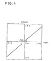
- FIG.4 is an input-output characteristic of a nonlinear conversion means in the first embodiment of the present invention.
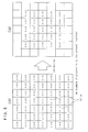
- FIG.5 is an example of explanatory tables of data results processed by the first embodiment of the present invention.
- FIG.6 is an example of explanatory tables of data corresponding to those of FIG.5 but processed by the prior art.
- FIG.7 is an input-output characteristic of a nonlinear conversion means in a second embodiment of the present invention.
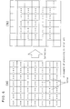
- FIG.8 is an example of explanatory tables of results processed by the second embodiment of the present invention.
- FIG.9 is an example of explanatory tables of data corresponding to those of FIG.8 but processed by the prior art.
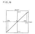
- FIG.10 is an input-output characteristic of a nonlinear conversion means in a third embodiment of the present invention.
- FIG.11 is an example of explanatory tables of results processed by the third embodiment of the present invention.
- FIG.12 is an example of explanatory tables of data corresponding to those of FIG.11 but processed by the prior art.
- FIG.13 is an input-output characteristic of a nonlinear conversion means in a fourth embodiment of the present invention.
- FIG.14 is an example of the explanatory tables of results processed by the fourth embodiment of the present invention.
- FIG.15 shows an example of explanatory tables of data corresponding to those of FIG.14 but processed by the prior art.
- FIG.16 is a block diagram of one example of a second logic processing apparatus in a second embodiment circuit configuration.
- the present invention is to offer a picture processing apparatus through which a smooth MTF correction on defocused images on a picture is achievable by enhancing stably contour lines included in the picture as well as by eliminating the noise of the picture without being influenced by the presence of noise.
- the data of respective reference pixels are subtracted from the datum of a relevant pixel, then those respective results are nonlinearly converted by a nonlinear conversion means, and by adding the output thereof again to the datum of the relevant pixel the subtracted result between the datum of the relevant pixel having noise and the data of the reference pixels is made to be zero, and thereby the MTF correction is achieved.
- a variation mode of the embodiment of the present invention has, besides the above-mentioned configuration, such feature that the input characteristic of the nonlinear conversion means is continuous, and when the absolute value of the input is less than a first threshold value, the output becomes zero, whereas when the absolute value of the input is greater than the first threshold value, it becomes a monotonously increasing function and in addition to that the increment of its slope with respect to the increase of the absolute value of the input, at least, does not become negative.
- responding to the difference between the relevant pixel and the reference pixels that is, responding to the Laplacian component which is the second order derivative of the picture image
- a nonlinear conversion means having a nonlinear conversion characteristic whose input-output characteristic is continuous, and when the absolute value of the input is less than a specified value, its output becomes zero, whereas when it is greater than the specified value, it is expressed by a monotonously increasing function.
- the input-output characteristic is continuous and when the absolute value of the input is less than the first threshold value, the output is zero, whereas when the absolute value of the input is greater than the first threshold value, it is a monotonously increasing function, and the increment of its slope with respect to the increase of the absolute value of the input, at least, does not become to be negative, without enhancing the noise components and also without introducing any interruption on the contour lines, a smooth continuous contour lines can be obtained.
- a further modified embodiment of the present invention is characterized in that the input-output characteristic of the nonlinear conversion means is continuous, and when the absolute value of the input is greater than a second threshold value which is greater than the first threshold value, its slope is smaller than a slope in a range in which the absolute value of the input is less than the second threshold value.
- the MTF correction which is suitable for the level difference on the contour lines can be achieved.
- the MTF correction can be made by decreasing the amount of correction in case the level differences between adjacent pixels before performing the correction are large (that is, in case the level differences on contour lines are large.
- a still further modified embodiment of the present invention is characterized in that the input-output characteristic of the nonlinear conversion means is continuous, and when the absolute value of the input is less than a third threshold value which is less than the first threshold value, it is expressed by a monotonously decreasing function.
- a nonlinear conversion means by which, when the Laplacian component which is the second order derivative of the picture image is less than a specified value, a smoothing process is performed, whereas when it is greater than a specified value, an enhancement process is performed, is referenced from an arithmetically processed result between the relevant pixel and the reference pixels, and by adding this result to the datum of the relevant picture element, the MTF correction is achieved.
- the input-output characteristic of the nonlinear conversion means continuous and being able to be expressed by a monotonously decreasing function when the absolute value of the input is less than the third threshold value, the low-level noise components in the high frequency range are smoothed out, thereby a picture image in which the noise is eliminated and only the contour lines are enhanced is obtainable. Thus the effect in its practical application usage is great.
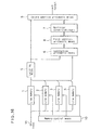
- FIG.2 shows a block diagram of a picture processing apparatus of a first embodiment of the present invention.
- numerals 1 to 4 are line memories which are capable of memorizing picture image signals of an amount of as much as one line;
- numeral 5 is latching means which keeps data of a relevant pixel given from the line memory 1, 2, 3 or 4;
- numeral 6 is subtraction arithmetic means which performs subtraction calculation of data of four reference pixels from the data of the relevant pixel kept in the latching means 5;
- numeral 7 is nonlinear conversion means which performs nonlinear conversions to be described later on the output of the subtraction arithmetic means 6 and is constituted by a table memory using a ROM in the present embodiment.
- Numeral 8 is first addition arithmetic means which performs successive addition calculations of outputs of the nonlinear conversion means 7;
- numeral 9 is second addition arithmetic means which performs an addition calculation between the output of the first addition arithmetic means 8 and the output of the latching means 5;
- numeral 10 is a memory control means which performs controls of line memories 1, 2, 3, and 4.
- the latching means 5, subtraction arithmetic means 6, non-linear conversion means 7, first and second addition arithmetic means 8 and 9, memory control means 10 may be constituted by hard circuits, but at least some of them may be constituted by known microcomputer functions.
- FIG.3 is a timing chart for explaining the first embodiment in the present invention.
- size or scale of the matrix of a spatial filter is selected to be 3 ⁇ 3.
- the designation convention of elements of this matrix is shown in FIG.1. That is, the datum of a relevant pixel P(i,j) is designated as D(i,j), and data of reference pixels P(i-1,j), P(i+1,j), P(i,j-1) and P(i,j+1) are designated as D(i-1,j), D(i+1,j), D(i,j-1) and D(i,j+1).
- the line memory 4 whereof the datum D(i,j) of the relevant or considered pixel P(i,j) is stored is the line memory 2.
- the datum D(i,j) of the relevant pixel P(i,j) is stored in the line memory 2
- the data D(i-1,j) and D(i+1,j) of the reference pixels P(i-1,j) and P(i+1,j) are stored in the line memory 2
- the datum D(i,j+1) of the reference pixel P(i,j+1) is stored in the line memory 3, respectively.
- This output K2 and the afore-mentioned output K1 are added to each other by the first addition arithmetic means. Also for the subsequent steps, similar processes are applied, and thereby the subtraction between the relevant picture element and the reference pixels is repeated. The resultant outputs of K1 up to K4 are successively summed up.
- the MTF correction process of the present invention can be expressed by the following equation (2).
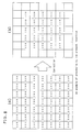
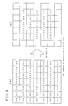
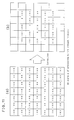
- FIG.5, FIG.8, and FIG.11 show examples of the states of data of pixels before and after the processings using the nonlinear conversion means 7, whereby various input-output characteristics in accordance with the present embodiment and other respective embodiments are processed.
- examples using conventional schemes corresponding respectively to the above embodiments are shown in FIG.6, FIG.9, and FIG.12.
- FIG.6, FIG.9, and FIG.12. These figures illustrate parts of whole picture images.
- figures (a) represent partial picture images to be processed
- figures (b) represent partial picture images after processings, respectively.
- Respective picture image data are assumed to be represented by 8 bits. Those pixels aligning along inside the periphery in figures (b) are left blank, because these pixels require, to be filled, basing on data outside the periphery of the picture image of figures (a), which are not given.
- FIG.4 is a characteristic curve showing an input-output characteristic of the nonlinear conversion means 7 of the present embodiment of the present invention.
- the output of the subtraction arithmetic means 6 that is, the resultant difference of a subtraction of the data of reference pixels from the datum of the relevant pixel is taken, and on the ordinate the output S' n is taken, respectively.
- TH1 a first specified threshold value
- TH1 the input-output characteristic
- FIG.5 An example of the processed results of the present first embodiment using the nonlinear conversion means 7 having the input-output characteristic described above is shown in FIG.5.
- FIG.5 (a) illustrates picture image data before the correction, and (b) picture image data after the correction, as mentioned before.
- FIG.6 An example of processed results of a conventional scheme is shown in FIG.6.
- pixels having a level of 215 represent noises
- pixels having a level of 160 represent a gray contour line
- pixels having a level of 230 represent a white flat area.
- FIG.5 Comparison between FIG.5 and FIG.6 reveals the following:
- the conventional scheme of FIG.6 has inconvenience such that those pixels adjacent to the contour line, whose levels are originally expected to be constant, make undesirable level change.
- data of those pixels adjacent to the contour line can keep a constant level.
- the nonlinear conversion means 7 has been taken to be a memory table using a ROM
- a certain other scheme can be employed such that: by selecting a correction factor (in the present embodiment, 0 or ⁇ ) responding to the subtraction result (difference) between the relevant pixel and the reference pixels, an amount of correction is obtained by multiplication by the selected correction factor.
- the input-output characteristic of a nonlinear conversion means 7 is determined in a manner that, when the absolute value of the input is less than a first specified threshold value (TH1) as shown in FIG.7, the output is zero or substantially zero; and on the other hand when the absolute value of the input is greater than the first threshold value (TH1), the input-output characteristic becomes a monotonously increasing function and an increase of its slope, at least, does not become negative.
- TH1 first specified threshold value
- the output of the nonlinear conversion means 7 becomes a monotonously increasing function which is continuous from zero as shown by the inequity (3). Accordingly the correction value thereof keeps its increase.
- FIG.8 shows an example of the result processed in accordance with the present embodiment using the nonlinear conversion means 7 having the input-output characteristic as shown in FIG.7.
- FIG.8 (a) illustrates picture image data before the correction, (b) picture image data after the correction, as mentioned before.
- the input-output characteristic of the nonlinear conversion means 7 is assumed to be,
- FIG.9 shows an example of the result processed by means of a conventional scheme, that is by the same scheme as in FIG.6.
- FIG.8 and FIG.9 reveals the following:
- the level variation on a contour line is gradual, according to the conventional scheme, as shown in FIG.9, the correction operation is terminated at the pixel at which the level is 210, after a certain midway of the contour line (In FIG.9(b)).
- the present invention as shown in FIG.8, even when the level variation on a contour line is gradual as shown in FIG.8, it can be seen that the correction operation continues until the original contour line stops.
- the input-output characteristic is taken as a combination of 1-st order functions
- other modification of other order functions may be used such that: for an amount of the MTF correction, when the slope of the absolute value of the input increases, the slope of the input-output characteristic, at least, does not become negative.
- a 2-nd order function can also be used.
- the input-output characteristic of a nonlinear conversion means 7 is determined to be continuous, and that when the absolute value of input is greater than a fourth threshold value (TH4) which is greater than the first threshold value (TH1), its slope is taken to be smaller than a maximum slope in a range in which the absolute value of the input is less than the fourth threshold value (TH4).
- TH4 fourth threshold value
- TH1 first threshold value
- the nonlinear conversion means when the absolute value of input is greater than a fourth threshold value (TH4), its slope is smaller than a maximum slope in a range in which the absolute value of the input is less than the fourth threshold value (TH4). Accordingly, when the absolute value of the subtracted result between the relevant pixel and the reference pixels is greater than the second threshold value, that is, when the absolute value of the subtracted result between the relevant pixel and the reference pixels is larger than a certain value, it means that the level difference between adjacent pixels before the correction becomes large. For such cases, an amount of correction becomes such that the degree of the contour enhancement by the MTF correction is weakened.
- FIG.11 an example of the processed result in accordance with the present embodiment using the nonlinear conversion means 7 having the input-output characteristic as shown in FIG.10 is shown.
- FIG.11 (a) illustrates picture image data before the correction, (b) picture image data after the correction, as mentioned before.
- the input-output characteristic of the nonlinear conversion means 7 is assumed to be,
- FIG.11 Comparison between FIG.11 and FIG.12 reveals the following: According to the conventional scheme, when the difference between the level of the contour line and the white flat area is large, as shown in FIG.12, the boundary area adjacent to the contour line is corrected exaggeratedly. On the other hand, according to the present invention, as shown in FIG.11, there is no such exaggerated correction in the boundary area adjacent to the contour line.
- the input-output characteristic of a nonlinear conversion means 7 is determined in a manner to be continuous, and that when the absolute value of input is less than the first threshold value (TH1) it is taken to be one expressed by a monotonously decreasing function. This input-output characteristic is shown in FIG.13.
- the input-output characteristic of the present embodiment is expressed as,
- this spatial filter acts as a low-pass filter.
- FIG.14 shows an example of the result processed in accordance with the present embodiment using the nonlinear conversion means 7 having the input-output characteristic as shown in FIG.13.
- FIG.14 (a) illustrates picture image data before the correction, (b) picture image data after the correction.
- the input-output characteristic of the nonlinear conversion means 7 is assumed to be,
- FIG.15 An example of the result processed by means of a conventional scheme, that is by the same scheme as in FIG.6 is shown in FIG.15.
- FIG.14 Comparison between FIG.14 and FIG.15 reveals the following:
- the conventional scheme when the difference between the level of the contour line and the white flat area is large, as shown in FIG.15, noises are left as they were before correction and they were issued without any correction.
- the present invention as shown in FIG.14, noises are smoothed out and thereby suppressing the noise of the picture image.
- the fourth embodiment results in smoothing out of the low-level noise components of high frequency range by a spatial filter.
- a spatial filter For example, it becomes possible to obtain a picture image without the granularities due to noise, and only the contour lines are enhanced.
- modified mode than the constitutions that have been described in the second, third, and fourth embodiments may be similarly used.
- a modified constitution as shown in FIG.16 such that: obtaining first the difference between the relevant pixel and a sum of nearest-neighboring pixels, that is, obtaining in advance the Laplacian component of second order derivative by arithmetic means 6 and 8; then the result thereof is nonlinearly converted by the nonlinear conversion means 7 having the input-output characteristic such as that explained in the foregoing embodiments; and thereafter the resultant converted data is added to the data of the relevant pixel.
Landscapes
- Physics & Mathematics (AREA)
- General Physics & Mathematics (AREA)
- Engineering & Computer Science (AREA)
- Theoretical Computer Science (AREA)
- Image Processing (AREA)
- Facsimile Image Signal Circuits (AREA)
- Picture Signal Circuits (AREA)
Claims (10)
- Bildverarbeitungsvorrichtung zum Verbessern der Schärfe einer Bildabbildung, aufweisend:mehrere Zeilenspeicher (1,2,3,4), jeweils zum Speichern einer Zeile eines Bildabbildungssignals,eine Verriegelungseinrichtung (5) zum Speichern eines relevanten Pixels, welches aus einem der Zeilenspeicher gelesen ist, in den Zeilenspeichern (1,2,3,4),eine Subtraktionseinrichtung (6) zum Subtrahieren von einem Datum des relevanten Pixels N (N > = 1) jeweilige Daten von N Pixeln, die aus den Zeilenspeichern erhalten sind, bei denen es sich um nächste Nachbarn des relevanten Pixels handelt, um N Subtraktionsausgangssignale zu erhalten,eine nichtlineare Wandlereinrichtung (7) zum nichtlinearen Wandeln der N Subtraktionsausgangssignale zum Erzeugen von N entsprechenden Wandlungsausgangssignalen,eine erste Additionseinrichtung (8) zum Addieren der N Wandlungsausgangssignale zum Erzeugen einer Wandlungssumme, undeine zweite Additionseinrichtung (9) zum Addieren des Datums des relevanten Pixels und der Wandlungssumme, um ein schärferes Bildpixel zu erzeugen.
- Vorrichtung nach Anspruch 1, wobei die nichtlineare Wandlereinrichtung (7)ein Wandlungsausgangssignal ausgibt, das im wesentlichen gleich null ist, wenn der Absolutwert eines entsprechenden Subtraktionsausgangssignals kleiner oder gleich einem ersten Schwellenwert (TH1) ist, undein Wandlungsausgangssignal auf Grundlage einer ersten linearen Funktion positiver Steigung von einem entsprechenden Subtraktionsausgangssignal ausgibt, wenn der Absolutwert des Subtraktionsausgangssignals größer als der erste Schwellenwert (TH1) ist.
- Vorrichtung nach Anspruch 2, wobei die nichtlineare Wandlereinrichtung (7)
ein Wandlungsausgangssignal auf Grundlage einer zweiten linearen Funktion positiver Steigung von einem entsprechenden Subtraktionsausgangssignal ausgibt, wenn der Absolutwert des Subtraktionsausgangssignals größer als ein zweiter Schwellenwert (TH2) ist, wobei der zweite Schwellenwert (TH2) größer als der erste Schwellenwert (TH1) ist und die zweite lineare Funktion positiver Steigung eine Steigung größer als die erste lineare Funktion positiver Steigung hat. - Vorrichtung nach Anspruch 3, wobei die nichtlineare Wandlereinrichtung (7)
ein Wandlungsausgangssignal auf Grundlage einer dritten linearen Funktion positiver Steigung von einem entsprechenden Subtraktionsausgangssignal ausgibt, wenn der Absolutwert des Subtraktionsausgangssignals größer als ein dritter Schwellenwert (TH3) ist, wobei der dritte Schwellenwert (TH3) größer als der zweite Schwellenwert (TH2) ist, und wobei die dritte lineare Funktion positiver Steigung eine Steigung größer als die zweite lineare Funktion positiver Steigung hat. - Vorrichtung nach Anspruch 1, wobei die nichtlineare Wandlereinrichtung (7)
ein Wandlungsausgangssignal auf Grundlage einer ersten linearen Funktion positiver Steigung von einem entsprechenden Subtraktionsausgangssignal ausgibt. - Vorrichtung nach Anspruch 5, wobei die nichtlineare Wandlereinrichtung (7)
ein Wandlungsausgangssignal auf Grundlage einer zweiten linearen Funktion positiver Steigung von einem entsprechenden Subtraktionsausgangssignal ausgibt, wenn der Absolutwert des Subtraktionsausgangssignals größer als ein vierter Schwellenwert (TH4) ist, wobei die zweite lineare Funktion positiver Steigung eine Steigung kleiner als die erste lineare Funktion positiver Steigung hat. - Vorrichtung nach Anspruch 1, wobei die nichtlineare Wandlereinrichtung (7)
ein Wandlungsausgangssignal auf Grundlage einer linearen Funktion negativer Steigung von einem entsprechenden Subtraktionsausgangssignal ausgibt. - Vorrichtung nach Anspruch 7, wobei die nichtlineare Wandlereinrichtung (7)
ein Wandlungsausgangssignal auf Grundlage einer linearen Funktion positiver Steigung von einem entsprechenden Subtraktionsausgangssignal ausgibt, wenn der Absolutwert des Subtraktionsausgangssignals größer als ein dritter Schwellenwert (TH3) ist. - Vorrichtung nach Anspruch 1, wobei die nichtlineare Wandlereinrichtung (7)ein Wandlungsausgangssignal im wesentlichen gleich null ausgibt, wenn der Absolutwert eines entsprechenden Subtraktionsausgangssignals kleiner oder gleich einem ersten Schwellenwert (TH1) ist,ein Wandlungsausgangssignal auf Grundlage einer ersten linearen Funktion positiver Steigung von einem entsprechenden Subtraktionsausgangssignal ausgibt, wenn der Absolutwert des Subtraktionsausgangssignals größer als der erste Schwellenwert (TH1) ist,ein Wandlungsausgangssignal auf Grundlage einer zweiten linearen Funktion positiver Steigung von einem entsprechenden Subtraktionsausgangssignal ausgibt, wenn der Absolutwert des Subtraktionsausgangssignals größer als ein zweiter Schwellenwert (TH2) ist, wobei der zweite Schwellenwert (TH2) größer als der erste Schwellenwert (TH1) ist, und wobei die zweite lineare Funktion positiver Steigung eine Steigung größer als die erste lineare Funktion positiver Steigung hat, undein Wandlungsausgangssignal auf Grundlage einer dritten linearen Funktion positiver Steigung von einem entsprechenden Subtraktionsausgangssignal ausgibt, wenn der Absolutwert des Subtraktionsausgangssignals größer als ein dritter Schwellenwert (TH3) ist, wobei der dritte Schwellenwert (TH3) größer als der zweite Schwellenwert (TH2) ist, und die dritte lineare Funktion positiver Steigung eine Steigung größer als die zweite lineare Funktion positiver Steigung hat.
- Bildverarbeitungsvorrichtung zum Verbessern der Schärfe einer Bildabbildung, aufweisend:mehrere Zeilenspeicher (1,2,3,4), von denen jeder eine Zeile eines Bildabbildungssignals speichert,eine Verriegelungseinrichtung (5) zum Speichern eines relevanten Pixels, das aus einem der Zeilenspeicher ausgelesen ist, in den Zeilenspeichern (1,2,3,4),eine Subtraktionseinrichtung (6) zum Subtrahieren von einem Datum des relevanten Pixels N (N > = 1) jeweilige Daten von N Pixeln, die aus den Zeilenspeichern erhalten sind, wobei es sich bei diesen um nächste Nachbarn des relevanten Pixels handelt, um N Subtraktionsausgangssignale zu erzeugen,eine erste Additionseinrichtung (8) zum Addieren der N Subtraktionsausgangssignale zum Erzeugen einer Wandlungssumme,eine nichtlineare Wandlereinrichtung (7) zum nichtlinearen Wandeln der Wandlungssumme zum Erzeugen eines entsprechenden Wandlungsausgangssignals, undeine zweite Additionseinrichtung (9) zum Addieren des Datums des relevanten Pixels und des Wandlungsausgangssignals zur Erzeugung eines schärferen Bildpixels.
Applications Claiming Priority (2)
| Application Number | Priority Date | Filing Date | Title |
|---|---|---|---|
| JP2043026A JPH03245675A (ja) | 1990-02-23 | 1990-02-23 | 画像処理装置 |
| JP43026/90 | 1990-02-23 |
Publications (3)
| Publication Number | Publication Date |
|---|---|
| EP0443486A2 EP0443486A2 (de) | 1991-08-28 |
| EP0443486A3 EP0443486A3 (en) | 1991-11-27 |
| EP0443486B1 true EP0443486B1 (de) | 1998-01-21 |
Family
ID=12652438
Family Applications (1)
| Application Number | Title | Priority Date | Filing Date |
|---|---|---|---|
| EP91102269A Expired - Lifetime EP0443486B1 (de) | 1990-02-23 | 1991-02-18 | Bildverarbeitungsgerät |
Country Status (5)
| Country | Link |
|---|---|
| US (1) | US5144686A (de) |
| EP (1) | EP0443486B1 (de) |
| JP (1) | JPH03245675A (de) |
| KR (1) | KR940002484B1 (de) |
| DE (1) | DE69128733T2 (de) |
Families Citing this family (14)
| Publication number | Priority date | Publication date | Assignee | Title |
|---|---|---|---|---|
| DE69214229T2 (de) * | 1991-08-14 | 1997-04-30 | Agfa Gevaert Nv | Verfahren und Vorrichtung zur Kontrastverbesserung von Bildern |
| JPH05336365A (ja) * | 1992-05-28 | 1993-12-17 | Canon Inc | 画像形成装置 |
| EP0610606A1 (de) * | 1993-02-11 | 1994-08-17 | Agfa-Gevaert N.V. | Verfahren zur Darstellung eines Bildteils |
| US5696850A (en) * | 1995-12-21 | 1997-12-09 | Eastman Kodak Company | Automatic image sharpening in an electronic imaging system |
| EP0788070A3 (de) * | 1996-01-31 | 1998-08-19 | EASTMAN KODAK COMPANY (a New Jersey corporation) | Verfahren zur Formung eines Verschärfungs-/Verzerrungsfilters |
| US6728003B1 (en) | 2000-04-04 | 2004-04-27 | Eastman Kodak Company | Method of compensating for MTF in a digital image channel |
| KR20040092763A (ko) * | 2003-04-29 | 2004-11-04 | 삼성전자주식회사 | 이진 데이터 검출 방법 및 그 장치 |
| JP2007243349A (ja) * | 2006-03-06 | 2007-09-20 | Brother Ind Ltd | 画像読取装置および画像読取方法 |
| WO2009040417A2 (en) * | 2007-09-28 | 2009-04-02 | Oce-Technologies B.V. | Method, apparatus and computer program for adaptive compensation of a mtf |
| CN102100060A (zh) * | 2008-07-14 | 2011-06-15 | 夏普株式会社 | 视频信号处理装置和视频显示装置 |
| JP5623063B2 (ja) * | 2009-11-16 | 2014-11-12 | キヤノン株式会社 | 画像処理装置およびその方法 |
| CN102109753A (zh) * | 2009-12-25 | 2011-06-29 | 鸿富锦精密工业(深圳)有限公司 | 自动检测镜头方法 |
| JP5530219B2 (ja) | 2010-02-26 | 2014-06-25 | 日本航空電子工業株式会社 | サーボ型加速度計 |
| JP5889013B2 (ja) * | 2012-02-01 | 2016-03-22 | キヤノン株式会社 | 画像処理装置及び画像処理方法 |
Family Cites Families (6)
| Publication number | Priority date | Publication date | Assignee | Title |
|---|---|---|---|---|
| JPS5279747A (en) * | 1975-12-26 | 1977-07-05 | Sony Corp | Noise removal circuit |
| US4517607A (en) * | 1981-11-09 | 1985-05-14 | Ricoh Company, Ltd. | Method of and apparatus for compensating image in image reproduction system |
| JPS61236274A (ja) * | 1985-04-12 | 1986-10-21 | Ricoh Co Ltd | 画デ−タ処理方式 |
| JPS62149265A (ja) * | 1985-12-23 | 1987-07-03 | Fuji Xerox Co Ltd | 画像輪郭強調装置 |
| DE3629409C2 (de) * | 1986-08-29 | 1994-02-17 | Agfa Gevaert Ag | Verfahren und Vorrichtung zur Kontrastbewertung bei der elektronischen Bildverarbeitung |
| US4941190A (en) * | 1988-07-15 | 1990-07-10 | Minnesota Mining And Manufacturing Company | Method and system for enhancement of a digitized image |
-
1990
- 1990-02-23 JP JP2043026A patent/JPH03245675A/ja active Pending
-
1991
- 1991-02-07 US US07/652,076 patent/US5144686A/en not_active Expired - Fee Related
- 1991-02-18 EP EP91102269A patent/EP0443486B1/de not_active Expired - Lifetime
- 1991-02-18 DE DE69128733T patent/DE69128733T2/de not_active Expired - Fee Related
- 1991-02-23 KR KR1019910002961A patent/KR940002484B1/ko not_active Expired - Fee Related
Also Published As
| Publication number | Publication date |
|---|---|
| EP0443486A3 (en) | 1991-11-27 |
| KR920000013A (ko) | 1992-01-10 |
| US5144686A (en) | 1992-09-01 |
| JPH03245675A (ja) | 1991-11-01 |
| EP0443486A2 (de) | 1991-08-28 |
| DE69128733D1 (de) | 1998-02-26 |
| KR940002484B1 (ko) | 1994-03-24 |
| DE69128733T2 (de) | 1998-04-30 |
Similar Documents
| Publication | Publication Date | Title |
|---|---|---|
| US5144686A (en) | Mtf compensation apparatus | |
| US4941190A (en) | Method and system for enhancement of a digitized image | |
| US4660082A (en) | Output correction in image reproduction | |
| US5243444A (en) | Image processing system and method with improved reconstruction of continuous tone images from halftone images including those without a screen structure | |
| US4811115A (en) | Image processing apparatus using approximate auto correlation function to detect the frequency of half-tone image data | |
| US4841374A (en) | Image processing method | |
| EP1494462A1 (de) | Bildverarbeitungseinrichtung und -verfahren | |
| EP1404120A1 (de) | Bildverarbeitungsverfahren und -einrichtung | |
| JP3489796B2 (ja) | 画像信号処理装置 | |
| JPS5810966A (ja) | 撮像画素のしきり処理のための最適しぎ値決定方法 | |
| US5936684A (en) | Image processing method and image processing apparatus | |
| JP2973899B2 (ja) | 画像処理装置 | |
| US5493416A (en) | Method combining error diffusion and traditional halftoning with arbitrary screen orientation | |
| JP3031994B2 (ja) | 画像処理装置 | |
| US6005989A (en) | Method for modifying the resolution of a digitized image | |
| US5988504A (en) | Optical scanner using weighted adaptive threshold | |
| US5144399A (en) | Color image pickup apparatus | |
| US5448656A (en) | Binary image processing apparatus | |
| US5532827A (en) | Apparatus for reproducing image densities using pixel processing and method of use thereof | |
| US5572337A (en) | Shading correcting method and shading correcting apparatus | |
| US5337162A (en) | Image processing apparatus for preventing occurrence of moire in output image | |
| JPH04321379A (ja) | 適応画像強調回路 | |
| JP3633728B2 (ja) | 画像欠陥補正回路 | |
| JP4065463B2 (ja) | 画像処理装置、画像処理方法、及びコンピュータ読み取り可能な記録媒体 | |
| JPH09212642A (ja) | 画像処理装置 |
Legal Events
| Date | Code | Title | Description |
|---|---|---|---|
| PUAI | Public reference made under article 153(3) epc to a published international application that has entered the european phase |
Free format text: ORIGINAL CODE: 0009012 |
|
| 17P | Request for examination filed |
Effective date: 19910218 |
|
| AK | Designated contracting states |
Kind code of ref document: A2 Designated state(s): DE FR GB |
|
| PUAL | Search report despatched |
Free format text: ORIGINAL CODE: 0009013 |
|
| AK | Designated contracting states |
Kind code of ref document: A3 Designated state(s): DE FR GB |
|
| 17Q | First examination report despatched |
Effective date: 19960112 |
|
| GRAG | Despatch of communication of intention to grant |
Free format text: ORIGINAL CODE: EPIDOS AGRA |
|
| GRAG | Despatch of communication of intention to grant |
Free format text: ORIGINAL CODE: EPIDOS AGRA |
|
| GRAG | Despatch of communication of intention to grant |
Free format text: ORIGINAL CODE: EPIDOS AGRA |
|
| GRAH | Despatch of communication of intention to grant a patent |
Free format text: ORIGINAL CODE: EPIDOS IGRA |
|
| GRAH | Despatch of communication of intention to grant a patent |
Free format text: ORIGINAL CODE: EPIDOS IGRA |
|
| GRAA | (expected) grant |
Free format text: ORIGINAL CODE: 0009210 |
|
| AK | Designated contracting states |
Kind code of ref document: B1 Designated state(s): DE FR GB |
|
| REF | Corresponds to: |
Ref document number: 69128733 Country of ref document: DE Date of ref document: 19980226 |
|
| ET | Fr: translation filed | ||
| PLBE | No opposition filed within time limit |
Free format text: ORIGINAL CODE: 0009261 |
|
| STAA | Information on the status of an ep patent application or granted ep patent |
Free format text: STATUS: NO OPPOSITION FILED WITHIN TIME LIMIT |
|
| 26N | No opposition filed | ||
| REG | Reference to a national code |
Ref country code: GB Ref legal event code: IF02 |
|
| PGFP | Annual fee paid to national office [announced via postgrant information from national office to epo] |
Ref country code: FR Payment date: 20020212 Year of fee payment: 12 |
|
| PGFP | Annual fee paid to national office [announced via postgrant information from national office to epo] |
Ref country code: GB Payment date: 20020220 Year of fee payment: 12 |
|
| PGFP | Annual fee paid to national office [announced via postgrant information from national office to epo] |
Ref country code: DE Payment date: 20020306 Year of fee payment: 12 |
|
| PG25 | Lapsed in a contracting state [announced via postgrant information from national office to epo] |
Ref country code: GB Free format text: LAPSE BECAUSE OF NON-PAYMENT OF DUE FEES Effective date: 20030218 |
|
| PG25 | Lapsed in a contracting state [announced via postgrant information from national office to epo] |
Ref country code: DE Free format text: LAPSE BECAUSE OF NON-PAYMENT OF DUE FEES Effective date: 20030902 |
|
| GBPC | Gb: european patent ceased through non-payment of renewal fee | ||
| PG25 | Lapsed in a contracting state [announced via postgrant information from national office to epo] |
Ref country code: FR Free format text: LAPSE BECAUSE OF NON-PAYMENT OF DUE FEES Effective date: 20031031 |
|
| REG | Reference to a national code |
Ref country code: FR Ref legal event code: ST |