EP0443424A1 - Getriebe-Steuerung für Fahrzeuge mit stufenlos verstellbarem Antrieb - Google Patents
Getriebe-Steuerung für Fahrzeuge mit stufenlos verstellbarem Antrieb Download PDFInfo
- Publication number
- EP0443424A1 EP0443424A1 EP91101987A EP91101987A EP0443424A1 EP 0443424 A1 EP0443424 A1 EP 0443424A1 EP 91101987 A EP91101987 A EP 91101987A EP 91101987 A EP91101987 A EP 91101987A EP 0443424 A1 EP0443424 A1 EP 0443424A1
- Authority
- EP
- European Patent Office
- Prior art keywords
- control system
- grip
- fact
- speed drive
- actuator
- Prior art date
- Legal status (The legal status is an assumption and is not a legal conclusion. Google has not performed a legal analysis and makes no representation as to the accuracy of the status listed.)
- Granted
Links
Images

Classifications
-
- B—PERFORMING OPERATIONS; TRANSPORTING
- B60—VEHICLES IN GENERAL
- B60K—ARRANGEMENT OR MOUNTING OF PROPULSION UNITS OR OF TRANSMISSIONS IN VEHICLES; ARRANGEMENT OR MOUNTING OF PLURAL DIVERSE PRIME-MOVERS IN VEHICLES; AUXILIARY DRIVES FOR VEHICLES; INSTRUMENTATION OR DASHBOARDS FOR VEHICLES; ARRANGEMENTS IN CONNECTION WITH COOLING, AIR INTAKE, GAS EXHAUST OR FUEL SUPPLY OF PROPULSION UNITS IN VEHICLES
- B60K20/00—Arrangement or mounting of change-speed gearing control devices in vehicles
- B60K20/02—Arrangement or mounting of change-speed gearing control devices in vehicles of initiating means
-
- F—MECHANICAL ENGINEERING; LIGHTING; HEATING; WEAPONS; BLASTING
- F16—ENGINEERING ELEMENTS AND UNITS; GENERAL MEASURES FOR PRODUCING AND MAINTAINING EFFECTIVE FUNCTIONING OF MACHINES OR INSTALLATIONS; THERMAL INSULATION IN GENERAL
- F16H—GEARING
- F16H59/00—Control inputs to control units of change-speed-, or reversing-gearings for conveying rotary motion
- F16H59/02—Selector apparatus
- F16H59/04—Ratio selector apparatus
- F16H59/06—Ratio selector apparatus the ratio being infinitely variable
-
- Y—GENERAL TAGGING OF NEW TECHNOLOGICAL DEVELOPMENTS; GENERAL TAGGING OF CROSS-SECTIONAL TECHNOLOGIES SPANNING OVER SEVERAL SECTIONS OF THE IPC; TECHNICAL SUBJECTS COVERED BY FORMER USPC CROSS-REFERENCE ART COLLECTIONS [XRACs] AND DIGESTS
- Y10—TECHNICAL SUBJECTS COVERED BY FORMER USPC
- Y10T—TECHNICAL SUBJECTS COVERED BY FORMER US CLASSIFICATION
- Y10T74/00—Machine element or mechanism
- Y10T74/19—Gearing
- Y10T74/19219—Interchangeably locked
- Y10T74/19251—Control mechanism
-
- Y—GENERAL TAGGING OF NEW TECHNOLOGICAL DEVELOPMENTS; GENERAL TAGGING OF CROSS-SECTIONAL TECHNOLOGIES SPANNING OVER SEVERAL SECTIONS OF THE IPC; TECHNICAL SUBJECTS COVERED BY FORMER USPC CROSS-REFERENCE ART COLLECTIONS [XRACs] AND DIGESTS
- Y10—TECHNICAL SUBJECTS COVERED BY FORMER USPC
- Y10T—TECHNICAL SUBJECTS COVERED BY FORMER US CLASSIFICATION
- Y10T74/00—Machine element or mechanism
- Y10T74/20—Control lever and linkage systems
- Y10T74/20012—Multiple controlled elements
- Y10T74/20018—Transmission control
- Y10T74/2003—Electrical actuator
-
- Y—GENERAL TAGGING OF NEW TECHNOLOGICAL DEVELOPMENTS; GENERAL TAGGING OF CROSS-SECTIONAL TECHNOLOGIES SPANNING OVER SEVERAL SECTIONS OF THE IPC; TECHNICAL SUBJECTS COVERED BY FORMER USPC CROSS-REFERENCE ART COLLECTIONS [XRACs] AND DIGESTS
- Y10—TECHNICAL SUBJECTS COVERED BY FORMER USPC
- Y10T—TECHNICAL SUBJECTS COVERED BY FORMER US CLASSIFICATION
- Y10T74/00—Machine element or mechanism
- Y10T74/20—Control lever and linkage systems
- Y10T74/20012—Multiple controlled elements
- Y10T74/20018—Transmission control
- Y10T74/2014—Manually operated selector [e.g., remotely controlled device, lever, push button, rotary dial, etc.]
Definitions
- the present invention relates to an automatic transmission control system for cars comprising a variable-speed drive enabling the velocity ratio of an input and output shaft to be varied continuously.
- variable-speed drive On transmissions of the aforementioned type, the variable-speed drive is normally operated by an actuator controlled by an electronic control system on the basis of engine and vehicle operating parameters. It also includes a gear lever with a number of settings, at least one of which enables the actuator to receive electric signals from the control system for activating the variable-speed drive.
- gear lever When the gear lever is so set, the velocity ratio best suited to the operating conditions of the engine and the vehicle is selected automatically according to the strategy memorised on the electronic control system, with no possibility of it being modified directly by the driver of the vehicle.
- the velocity ratio selected by the variable-speed drive may not always provide for optimum vehicle performance and consumption.
- engine braking is ineffective, due to the time required to achieve a substantial reduction in the velocity ratio.
- the aim of the present invention is to provide a control system for an automatic transmission of the aforementioned type, designed to overcome the aforementioned drawbacks, i.e. which provides for optimum vehicle performance and consumption, as well as for effective engine braking via direct intervention on the part of the driver.
- an automatic transmission control system for cars comprising a variable-speed drive enabling the velocity ratio of an input shaft and an output shaft to be varied continuously; said drive being activated by an actuator controlled by an electronic control system on the basis of engine and vehicle operating parameters; and said transmission also comprising a gear lever with a number of settings, at least one of which enables said actuator to receive electric signals from said control system for activating said variable-speed drive; characterised by the fact that it comprises an actuating member located and operated manually on said gear lever; a detector for detecting the setting of said actuating member and generating electric signals proportional to the same; and at least an electric circuit for generating electric signals for controlling and setting said actuator to predetermined positions corresponding to velocity ratios of said variable-speed drive proportional to said electric control signals.
- the control system according to the present invention is applicable to automatic transmissions comprising a variable-speed drive 1 for continuously varying the velocity ratio of an input shaft 2 and output shaft 3.
- Said variable-speed drive may be of any known type, for example, whereby drive is effected by means of a continuous flexible member, e.g. a belt, wound about a drive and a driven pulley. On a drive of this type, the velocity ratio is varied by modifying the radius by which the continuous flexible member is wound on to at least one of the pulleys.
- Drive 1 is activated by any type of actuator 4, e.g. an electrohydraulic actuator, controlled by an electronic control system 5 on the basis of engine and vehicle operating parameters supplied to control system 5 over an electric conductor 6.
- actuator 4 e.g. an electrohydraulic actuator
- Control system 5 operates according to control strategies memorised inside the control system itself, whereby, for given values of the aforementioned parameters, signals are generated for controlling actuator 4 which in turn sets variable-speed drive 1 to a given velocity ratio.
- the transmission also comprises a gear lever 8 with a number of settings, at least one of which enables actuator 4 to receive electric signals from control system 5 for activating variable-speed drive 1 as described previously.
- lever 8 is what is normally referred to as the "drive” setting, which corresponds to automatic control of variable-speed drive 1.
- Other known lever 8 settings may be: parking, neutral, reverse, and automatic drive control excluding the higher velocity ratios.
- the transmission also comprises an actuating member 9 located and operated manually on lever 8; a detector 11, for detecting the position of actuating member 9 and generating electric signals proportional to the same; and an electric circuit 12 (supposedly built into control system 5) for generating electric signals for controlling and setting actuator 4 to predetermined positions corresponding to velocity ratios of drive 1 proportional to said signals.
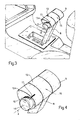
- Actuating member 9 conveniently consists of grip 13 of gear lever 8, which also comprises a laterally-projecting cylindrical appendix 14, the axis of which ("a” in Fig.s 2, 3 and 4) is perpendicular to the operating plane of lever 8.
- Grip 13 rotates about axis "a”, and is defined by an outer surface 15 off-centered in relation to axis "a”, so as to produce an eccentric grip portion 13a as shown in the accompanying drawings.
- Eccentric portion 13a of grip 13 conveniently faces the front of the vehicle, and outer surface 15 presents a substantially drop-shaped cross section perpendicular to axis "a".
- the cylindrical surface of appendix 14 presents a scale 16 with which cooperates a mark 17 on grip 13 for indicating the angle of grip 13 in relation to appendix 14.
- Both scale 16 and mark 17 are so formed as to be readily visible across the driver's portion of the vehicle, for which purpose, they may be formed either in relief or slightly recessed in relation to the respective surfaces.
- Setting detector 11 is conveniently located on lever 8 so as to generate electric signals for reducing the velocity ratio of variable-speed drive 1 when grip 13 is rotated so as to move eccentric portion 13a towards the driver.
- detector 11 when grip 13 is rotated from the Fig.2 or initial idle position to the Fig.3 position corresponding to maximum travel of actuating member 9, detector 11 generates signals for reducing the velocity ratio between two predetermined values.
- the transmission featuring the control system according to the present invention operates as follows.
- variable-speed drive 1 is controlled by actuator 4 solely on the basis of engine and vehicle operating parameters and according to the control strategy memorised in control system 5.
- actuator 4 is controlled via electric circuit 12 and on the basis of the signals generated by detector 11 relative to the position of actuating member 9.
- Each position of actuating member 9 corresponds to a predetermined value of the electric position signals sent to circuit 12 and, consequently, a predetermined value of the electric control signals generated by circuit 12 and sent to actuator 4.
- actuator 4 is set according to a predetermined velocity ratio of input shaft 2 and output shaft 3.
- Known means may be provided for ensuring lever 8 can only be set to the parking, reverse and "drive" positions by operating appendix 14.
- Electric circuit 12 and control system 5 may interact mutually in such a manner that, when actuating member 9 is set to other than said initial position, actuator 4 is controlled solely by electric circuit 12 as described, i.e. with no control signals generated by control system 5 for controlling actuator 4 on the basis of engine and vehicle operating parameters.
- control system in addition to fully automatic control of the transmission, the control system according to the present invention therefore also enables the driver, via actuating member 9, to set the velocity ratios best suited for optimizing vehicle consumption and performance according to the operating conditions of the vehicle. What is more, engine braking by the driver is rendered far more effective, to do which, actuating member 9 need simply be rotated towards the driver for immediately shifting to the low velocity ratios.
- actuating member 9 need simply be rotated towards the driver for immediately shifting to the low velocity ratios.
- An important point to note in connection with the engine braking operation is that, consisting as it does in simply rotating grip portion 13a towards the driver, it may be performed instinctively and, therefore, extremely rapidly.
- the velocity ratio set by rotating actuating member 9 is immediately perceptible, either visually or, if provision is made for the purpose, by simply feeling the position of mark 7 in relation to scale 16.
Applications Claiming Priority (2)
| Application Number | Priority Date | Filing Date | Title |
|---|---|---|---|
| IT6711490 | 1990-02-16 | ||
| IT67114A IT1241178B (it) | 1990-02-16 | 1990-02-16 | Sistema per il controllo di un cambio automatico per un autoveicolo del tipo comprendente un dispositivo variatore continuo. |
Publications (2)
| Publication Number | Publication Date |
|---|---|
| EP0443424A1 true EP0443424A1 (de) | 1991-08-28 |
| EP0443424B1 EP0443424B1 (de) | 1994-11-30 |
Family
ID=11299690
Family Applications (1)
| Application Number | Title | Priority Date | Filing Date |
|---|---|---|---|
| EP91101987A Expired - Lifetime EP0443424B1 (de) | 1990-02-16 | 1991-02-13 | Getriebe-Steuerung für Fahrzeuge mit stufenlos verstellbarem Antrieb |
Country Status (4)
| Country | Link |
|---|---|
| US (1) | US5142928A (de) |
| EP (1) | EP0443424B1 (de) |
| DE (1) | DE69105292T2 (de) |
| IT (1) | IT1241178B (de) |
Cited By (9)
| Publication number | Priority date | Publication date | Assignee | Title |
|---|---|---|---|---|
| FR2694525A1 (fr) * | 1992-08-06 | 1994-02-11 | Peugeot | Dispositif de commande d'une boîte de vitesses automatique. |
| EP0681119A2 (de) * | 1994-05-02 | 1995-11-08 | Aisin Aw Co., Ltd. | Fahrzeuggetriebesteuerungsanordnung |
| US5514050A (en) * | 1993-03-31 | 1996-05-07 | Robert Bosch Gmbh | Method for operating a motor vehicle having a continuously variable transmission by continuously changing the transmission ratio or detecting if a braking operation is present and continuously adjusting the transmission |
| GB2303183A (en) * | 1993-03-31 | 1997-02-12 | Bosch Gmbh Robert | Method for operating electronically controlled CVT has additional manual control |
| GB2310470A (en) * | 1996-02-20 | 1997-08-27 | Fuji Heavy Ind Ltd | A continuously-variable transmission for a vehicle with automatic and manual control modes |
| DE19609585A1 (de) * | 1996-03-12 | 1997-09-18 | Bayerische Motoren Werke Ag | Verfahren zum Steuern eines stufenlosen Getriebes sowie Vorrichtung hierzu |
| EP1114950A2 (de) * | 2000-01-06 | 2001-07-11 | Deere & Company | Bedienungseinrichtung für ein stufenloses Getriebe |
| CN101929543A (zh) * | 2009-06-25 | 2010-12-29 | 福特全球技术公司 | 用于机动车辆的自动变速器的变速杆装置 |
| FR3014843A1 (fr) * | 2013-12-12 | 2015-06-19 | Airbus Operations Sas | Dispositif de commande de la poussee d'au moins un moteur d'un aeronef et cockpit d'aeronef integrant un tel dispositif |
Families Citing this family (13)
| Publication number | Priority date | Publication date | Assignee | Title |
|---|---|---|---|---|
| JPH06159487A (ja) * | 1992-11-19 | 1994-06-07 | Kubota Corp | 農作業車の変速操作構造 |
| US5433124A (en) * | 1993-12-20 | 1995-07-18 | Ford Motor Company | Electronic range selection in an automatic transmission |
| US5437204A (en) * | 1993-12-20 | 1995-08-01 | Ford Motor Company | System for selecting the operating ranges of an automatic transmission |
| US5791197A (en) * | 1996-07-24 | 1998-08-11 | Grand Haven Stamped Products | Automatic transmission shifter with manual shift mode |
| DE19821403B4 (de) | 1998-05-13 | 2005-07-28 | ZF Lemförder Metallwaren AG | Wählvorrichtung für ein Fahrzeuggetriebe |
| US20060000304A1 (en) * | 2004-06-17 | 2006-01-05 | Deere & Company, A Delaware Corporation | Control lever with partially enclosed rotary wheel |
| US7637845B2 (en) | 2005-10-11 | 2009-12-29 | Caterpillar Inc. | System and method for controlling vehicle speed |
| US7544148B2 (en) * | 2005-12-27 | 2009-06-09 | Caterpillar Inc. | System and method for controlling vehicle speed |
| US7641588B2 (en) * | 2007-01-31 | 2010-01-05 | Caterpillar Inc. | CVT system having discrete selectable speed ranges |
| US8352138B2 (en) * | 2007-11-30 | 2013-01-08 | Caterpillar Inc. | Dynamic control system for continuously variable transmission |
| KR101421957B1 (ko) * | 2013-08-06 | 2014-07-22 | 현대자동차주식회사 | 오르간 타입 전자식 변속 레버 |
| US9019053B1 (en) * | 2013-12-09 | 2015-04-28 | Raymond Contreras | Multi-position magnetic rotary switch |
| KR102425035B1 (ko) * | 2017-10-16 | 2022-07-27 | 현대자동차주식회사 | 변속 장치를 포함하는 차량 |
Citations (4)
| Publication number | Priority date | Publication date | Assignee | Title |
|---|---|---|---|---|
| US3597991A (en) * | 1970-02-18 | 1971-08-10 | Gen Motors Corp | Transmission selector |
| EP0265035A1 (de) * | 1986-04-29 | 1988-04-27 | British Aerospace Public Limited Company | Handsteuervorrichtung für die Grösse und den Winkel des Schubvektors eines Flugzeuges |
| WO1989006395A1 (en) * | 1987-12-30 | 1989-07-13 | Caterpillar Inc. | Control mechanism for operating a vehicle |
| FR2636396A1 (fr) * | 1988-09-15 | 1990-03-16 | Peugeot | Dispositif de commande pour boite de vitesses automatique, notamment pour vehicule automobile |
Family Cites Families (6)
| Publication number | Priority date | Publication date | Assignee | Title |
|---|---|---|---|---|
| US2829533A (en) * | 1956-03-05 | 1958-04-08 | Battelle Development Corp | Automatic transmission control system |
| DE3434205A1 (de) * | 1984-09-18 | 1986-03-27 | Wabco Westinghouse Fahrzeugbremsen GmbH, 3000 Hannover | Geber fuer ein schaltgetriebe eines kraftfahrzeugs |
| US4964317A (en) * | 1987-08-10 | 1990-10-23 | Suzuki Jidosha Kogyo Kabushiki Kaisha | Hydraulic control method for continuously variable speed change gear mechanism for a vehicle and a drive control method for a pressure valve thereof |
| WO1990004119A1 (de) * | 1988-10-07 | 1990-04-19 | Zahnradfabrik Friedrichshafen Ag | Stelleinrichtung und steuerung für ein stufenloses automatgetriebe |
| US4966044A (en) * | 1989-05-30 | 1990-10-30 | J. I. Case Company | Directional control system for a tractor transmission |
| US4912997A (en) * | 1989-06-02 | 1990-04-03 | Chrysler Corporation | Electric shift selector mechanism for transmission |
-
1990
- 1990-02-16 IT IT67114A patent/IT1241178B/it active IP Right Grant
-
1991
- 1991-02-13 DE DE69105292T patent/DE69105292T2/de not_active Expired - Fee Related
- 1991-02-13 EP EP91101987A patent/EP0443424B1/de not_active Expired - Lifetime
- 1991-02-15 US US07/655,509 patent/US5142928A/en not_active Expired - Fee Related
Patent Citations (4)
| Publication number | Priority date | Publication date | Assignee | Title |
|---|---|---|---|---|
| US3597991A (en) * | 1970-02-18 | 1971-08-10 | Gen Motors Corp | Transmission selector |
| EP0265035A1 (de) * | 1986-04-29 | 1988-04-27 | British Aerospace Public Limited Company | Handsteuervorrichtung für die Grösse und den Winkel des Schubvektors eines Flugzeuges |
| WO1989006395A1 (en) * | 1987-12-30 | 1989-07-13 | Caterpillar Inc. | Control mechanism for operating a vehicle |
| FR2636396A1 (fr) * | 1988-09-15 | 1990-03-16 | Peugeot | Dispositif de commande pour boite de vitesses automatique, notamment pour vehicule automobile |
Non-Patent Citations (1)
| Title |
|---|
| PATENT ABSTRACTS OF JAPAN vol. 5, no. 47 (M-61)(719) 28 March 1981, & JP-A-56 002223 (KUBOTA TEKKO) 10 January 1981, * |
Cited By (15)
| Publication number | Priority date | Publication date | Assignee | Title |
|---|---|---|---|---|
| FR2694525A1 (fr) * | 1992-08-06 | 1994-02-11 | Peugeot | Dispositif de commande d'une boîte de vitesses automatique. |
| GB2303183B (en) * | 1993-03-31 | 1998-01-14 | Bosch Gmbh Robert | Method for operating a motor vehicle having a continuously variable transmission |
| US5514050A (en) * | 1993-03-31 | 1996-05-07 | Robert Bosch Gmbh | Method for operating a motor vehicle having a continuously variable transmission by continuously changing the transmission ratio or detecting if a braking operation is present and continuously adjusting the transmission |
| GB2303183A (en) * | 1993-03-31 | 1997-02-12 | Bosch Gmbh Robert | Method for operating electronically controlled CVT has additional manual control |
| GB2276683B (en) * | 1993-03-31 | 1998-01-14 | Bosch Gmbh Robert | Method for operating a motor vehicle having a continuously variable transmission |
| EP0681119A2 (de) * | 1994-05-02 | 1995-11-08 | Aisin Aw Co., Ltd. | Fahrzeuggetriebesteuerungsanordnung |
| EP0681119A3 (de) * | 1994-05-02 | 1997-06-11 | Aisin Aw Co | Fahrzeuggetriebesteuerungsanordnung. |
| GB2310470B (en) * | 1996-02-20 | 1998-05-13 | Fuji Heavy Ind Ltd | A continuously variable transmission for a vehicle and a method of control of a continuously variable transmission in a vehicle |
| GB2310470A (en) * | 1996-02-20 | 1997-08-27 | Fuji Heavy Ind Ltd | A continuously-variable transmission for a vehicle with automatic and manual control modes |
| DE19609585A1 (de) * | 1996-03-12 | 1997-09-18 | Bayerische Motoren Werke Ag | Verfahren zum Steuern eines stufenlosen Getriebes sowie Vorrichtung hierzu |
| EP1114950A2 (de) * | 2000-01-06 | 2001-07-11 | Deere & Company | Bedienungseinrichtung für ein stufenloses Getriebe |
| EP1114950A3 (de) * | 2000-01-06 | 2005-12-07 | Deere & Company | Bedienungseinrichtung für ein stufenloses Getriebe |
| CN101929543A (zh) * | 2009-06-25 | 2010-12-29 | 福特全球技术公司 | 用于机动车辆的自动变速器的变速杆装置 |
| CN101929543B (zh) * | 2009-06-25 | 2014-12-03 | 福特全球技术公司 | 用于机动车辆的自动变速器的变速杆装置 |
| FR3014843A1 (fr) * | 2013-12-12 | 2015-06-19 | Airbus Operations Sas | Dispositif de commande de la poussee d'au moins un moteur d'un aeronef et cockpit d'aeronef integrant un tel dispositif |
Also Published As
| Publication number | Publication date |
|---|---|
| EP0443424B1 (de) | 1994-11-30 |
| IT1241178B (it) | 1993-12-29 |
| DE69105292D1 (de) | 1995-01-12 |
| US5142928A (en) | 1992-09-01 |
| IT9067114A0 (it) | 1990-02-16 |
| IT9067114A1 (it) | 1991-08-16 |
| DE69105292T2 (de) | 1995-04-06 |
Similar Documents
| Publication | Publication Date | Title |
|---|---|---|
| EP0443424B1 (de) | Getriebe-Steuerung für Fahrzeuge mit stufenlos verstellbarem Antrieb | |
| US6821228B2 (en) | Control apparatus for continuously variable transmission | |
| EP0745503A4 (de) | Verfahren zur regelung der geschwindigkeitsänderung für ein elektrischen fahrzeug | |
| EP1593541A3 (de) | Steuerungsverfahren für Fahrzeug mit stufenlosem, verstellbarem Getriebe | |
| GB2269642B (en) | A multiple ratio geared transmission | |
| US5099720A (en) | Control mechanism for an automatic gear-shifting transmission using turn signal control unit | |
| EP1921350A3 (de) | Verfahren und Einrichtung zur Verbesserung des Schaltgefühls in automatisierten Schaltgetrieben | |
| JP2001193832A (ja) | ブレーキ作動中に変速機を制御する方法と装置 | |
| EP1177934A3 (de) | Übersetzungssteuerung für ein stufenloses Getriebe | |
| JP2002048226A (ja) | 自動変速機の変速制御装置 | |
| CA2342691C (en) | Method for controlling a continuously variable transmission | |
| CA2077427A1 (en) | Vehicle Automatic Transmission Control System | |
| EP0232686B1 (de) | Stufenlos regelbares Kraftfahrzeuggetriebe | |
| EP1069348A3 (de) | Vorrichtung zur Steuerung eines stufenlos verstellbaren Getriebes | |
| US5846160A (en) | Power transmission control | |
| JP4301962B2 (ja) | 無段階調整可能な複数の変速比領域を有する出力分岐型伝動装置と駆動モータとを有する車両ドライブトレーンの作動を制御するための方法および装置 | |
| JP2001341543A (ja) | 変速装置 | |
| SE9902959L (sv) | Elektronisk styrenhet för en växelanordning vid en flerhastighetsaxel | |
| EP0927657A3 (de) | Integrierte Vorrichtung zum Gangschalten eines Getriebes und eines mehrstufigem Achsgetriebes | |
| KR100250313B1 (ko) | 엔진 토크를 이용한 변속 제어장치 및 그 방법 | |
| JPH03204443A (ja) | 無段変速機の制御方式 | |
| JP2844647B2 (ja) | ロツクアツプクラツチを用いたエンジンブレーキ制御装置 | |
| JP2816466B2 (ja) | 車両用変速機の制御方法 | |
| JP3348622B2 (ja) | 無段変速機の変速制御装置 | |
| JPH09250636A (ja) | 車両用表示装置 |
Legal Events
| Date | Code | Title | Description |
|---|---|---|---|
| PUAI | Public reference made under article 153(3) epc to a published international application that has entered the european phase |
Free format text: ORIGINAL CODE: 0009012 |
|
| AK | Designated contracting states |
Kind code of ref document: A1 Designated state(s): DE ES FR GB SE |
|
| 17P | Request for examination filed |
Effective date: 19920129 |
|
| 17Q | First examination report despatched |
Effective date: 19930921 |
|
| GRAA | (expected) grant |
Free format text: ORIGINAL CODE: 0009210 |
|
| AK | Designated contracting states |
Kind code of ref document: B1 Designated state(s): DE ES FR GB SE |
|
| PG25 | Lapsed in a contracting state [announced via postgrant information from national office to epo] |
Ref country code: ES Free format text: THE PATENT HAS BEEN ANNULLED BY A DECISION OF A NATIONAL AUTHORITY Effective date: 19941130 |
|
| ET | Fr: translation filed | ||
| REF | Corresponds to: |
Ref document number: 69105292 Country of ref document: DE Date of ref document: 19950112 |
|
| PG25 | Lapsed in a contracting state [announced via postgrant information from national office to epo] |
Ref country code: SE Effective date: 19950228 |
|
| PLBE | No opposition filed within time limit |
Free format text: ORIGINAL CODE: 0009261 |
|
| STAA | Information on the status of an ep patent application or granted ep patent |
Free format text: STATUS: NO OPPOSITION FILED WITHIN TIME LIMIT |
|
| 26N | No opposition filed | ||
| PGFP | Annual fee paid to national office [announced via postgrant information from national office to epo] |
Ref country code: GB Payment date: 19990211 Year of fee payment: 9 |
|
| PG25 | Lapsed in a contracting state [announced via postgrant information from national office to epo] |
Ref country code: GB Free format text: LAPSE BECAUSE OF NON-PAYMENT OF DUE FEES Effective date: 20000213 |
|
| GBPC | Gb: european patent ceased through non-payment of renewal fee |
Effective date: 20000213 |
|
| PGFP | Annual fee paid to national office [announced via postgrant information from national office to epo] |
Ref country code: DE Payment date: 20040427 Year of fee payment: 14 |
|
| PGFP | Annual fee paid to national office [announced via postgrant information from national office to epo] |
Ref country code: FR Payment date: 20050131 Year of fee payment: 15 |
|
| PG25 | Lapsed in a contracting state [announced via postgrant information from national office to epo] |
Ref country code: DE Free format text: LAPSE BECAUSE OF NON-PAYMENT OF DUE FEES Effective date: 20050901 |
|
| REG | Reference to a national code |
Ref country code: FR Ref legal event code: ST Effective date: 20061031 |
|
| PG25 | Lapsed in a contracting state [announced via postgrant information from national office to epo] |
Ref country code: FR Free format text: LAPSE BECAUSE OF NON-PAYMENT OF DUE FEES Effective date: 20060228 |