EP0443108A2 - Safety ski binding with element for releasing the ski boot - Google Patents
Safety ski binding with element for releasing the ski boot Download PDFInfo
- Publication number
- EP0443108A2 EP0443108A2 EP90122245A EP90122245A EP0443108A2 EP 0443108 A2 EP0443108 A2 EP 0443108A2 EP 90122245 A EP90122245 A EP 90122245A EP 90122245 A EP90122245 A EP 90122245A EP 0443108 A2 EP0443108 A2 EP 0443108A2
- Authority
- EP
- European Patent Office
- Prior art keywords
- hold
- down device
- ski
- pin
- base
- Prior art date
- Legal status (The legal status is an assumption and is not a legal conclusion. Google has not performed a legal analysis and makes no representation as to the accuracy of the status listed.)
- Granted
Links
Images

Classifications
-
- A—HUMAN NECESSITIES
- A63—SPORTS; GAMES; AMUSEMENTS
- A63C—SKATES; SKIS; ROLLER SKATES; DESIGN OR LAYOUT OF COURTS, RINKS OR THE LIKE
- A63C9/00—Ski bindings
- A63C9/08—Ski bindings yieldable or self-releasing in the event of an accident, i.e. safety bindings
- A63C9/084—Ski bindings yieldable or self-releasing in the event of an accident, i.e. safety bindings with heel hold-downs, e.g. swingable
- A63C9/0846—Details of the release or step-in mechanism
-
- A—HUMAN NECESSITIES
- A63—SPORTS; GAMES; AMUSEMENTS
- A63C—SKATES; SKIS; ROLLER SKATES; DESIGN OR LAYOUT OF COURTS, RINKS OR THE LIKE
- A63C9/00—Ski bindings
- A63C9/08—Ski bindings yieldable or self-releasing in the event of an accident, i.e. safety bindings
-
- A—HUMAN NECESSITIES
- A63—SPORTS; GAMES; AMUSEMENTS
- A63C—SKATES; SKIS; ROLLER SKATES; DESIGN OR LAYOUT OF COURTS, RINKS OR THE LIKE
- A63C9/00—Ski bindings
- A63C9/08—Ski bindings yieldable or self-releasing in the event of an accident, i.e. safety bindings
- A63C9/084—Ski bindings yieldable or self-releasing in the event of an accident, i.e. safety bindings with heel hold-downs, e.g. swingable
- A63C9/0841—Ski bindings yieldable or self-releasing in the event of an accident, i.e. safety bindings with heel hold-downs, e.g. swingable with a single jaw
- A63C9/0842—Ski bindings yieldable or self-releasing in the event of an accident, i.e. safety bindings with heel hold-downs, e.g. swingable with a single jaw the jaw pivoting on the body or base about a transverse axis
-
- A—HUMAN NECESSITIES
- A63—SPORTS; GAMES; AMUSEMENTS
- A63C—SKATES; SKIS; ROLLER SKATES; DESIGN OR LAYOUT OF COURTS, RINKS OR THE LIKE
- A63C9/00—Ski bindings
- A63C9/08—Ski bindings yieldable or self-releasing in the event of an accident, i.e. safety bindings
- A63C9/084—Ski bindings yieldable or self-releasing in the event of an accident, i.e. safety bindings with heel hold-downs, e.g. swingable
- A63C9/0845—Ski bindings yieldable or self-releasing in the event of an accident, i.e. safety bindings with heel hold-downs, e.g. swingable the body or base or a jaw pivoting about a vertical axis, i.e. side release
-
- A—HUMAN NECESSITIES
- A63—SPORTS; GAMES; AMUSEMENTS
- A63C—SKATES; SKIS; ROLLER SKATES; DESIGN OR LAYOUT OF COURTS, RINKS OR THE LIKE
- A63C9/00—Ski bindings
- A63C9/08—Ski bindings yieldable or self-releasing in the event of an accident, i.e. safety bindings
- A63C9/0805—Adjustment of the toe or heel holders; Indicators therefor
-
- A—HUMAN NECESSITIES
- A63—SPORTS; GAMES; AMUSEMENTS
- A63C—SKATES; SKIS; ROLLER SKATES; DESIGN OR LAYOUT OF COURTS, RINKS OR THE LIKE
- A63C9/00—Ski bindings
- A63C9/08—Ski bindings yieldable or self-releasing in the event of an accident, i.e. safety bindings
- A63C9/084—Ski bindings yieldable or self-releasing in the event of an accident, i.e. safety bindings with heel hold-downs, e.g. swingable
- A63C9/0847—Details of the manual release
-
- A—HUMAN NECESSITIES
- A63—SPORTS; GAMES; AMUSEMENTS
- A63C—SKATES; SKIS; ROLLER SKATES; DESIGN OR LAYOUT OF COURTS, RINKS OR THE LIKE
- A63C9/00—Ski bindings
- A63C9/08—Ski bindings yieldable or self-releasing in the event of an accident, i.e. safety bindings
- A63C9/085—Ski bindings yieldable or self-releasing in the event of an accident, i.e. safety bindings with sole hold-downs, e.g. swingable
- A63C9/08535—Ski bindings yieldable or self-releasing in the event of an accident, i.e. safety bindings with sole hold-downs, e.g. swingable with a mobile body or base or single jaw
- A63C9/08542—Ski bindings yieldable or self-releasing in the event of an accident, i.e. safety bindings with sole hold-downs, e.g. swingable with a mobile body or base or single jaw pivoting about a transversal axis
Definitions
- the invention relates to a safety ski binding for releasable mounting of a ski boot, with two base parts which can be pivoted together about a ski-fixed pin with a non-circular cross section which is perpendicular to the top of the ski and which can be pushed apart in the longitudinal direction of the shoe against the force of a spring unit which is effective between them and can be pushed apart by the spring unit against opposite sides of the pin curious, which, due to its non-circular cross-section, moves the base parts apart when they pivot from a normal position into an inclined position, and with coupling elements arranged on the base parts, which in the normal position of the base parts are form-fitting and essentially free of play with shoe-resistant counter-coupling elements for ski-fixed mounting of the Ski boots interact and release its counter-coupling elements when the base parts are pushed apart to trigger the ski boot, a hold-down device arranged on a base part as a coupling element, between a locking position and a lockable release position moving in the direction of the ski vertical axis
- the hold-down device arranged on one base part has cams, which interact with associated links on the other base part, in such a way that the two base parts are held in a released position relative to one another by the cams and the link tracks in the released position of the hold-down device.
- a separate locking piston is arranged on a base part, which is pressed by means of a separate spring against a flattened side of the pin facing.
- an actuating force can be generated which tries to bring the base parts into a position in which the longitudinal axis of the base parts runs parallel to the longitudinal axis of the ski and the base part opposite the piston is pressed against the side of the pin facing away from the piston.
- This construction is relatively complex, i.e. a large number of moving parts relative to each other causes greater friction.
- the triggering resistance of the ski binding is influenced not only by the pretension of the spring assembly, but also by the tension of the additional spring acting on the locking piston.
- the object of the invention is now to achieve a simplified construction and improved handling in a ski binding of the type specified at the outset.
- the hold-down device in its release position keeps a base part from the ski-fixed pin, on which the hold-down device is supported directly or indirectly, against the force of the spring unit.
- the hold-down device can interact directly with parts arranged on it or indirectly via transmission parts with the pin, to move the base part carrying the hold-down device off the pin.
- the spring assembly which is clamped between the two base parts and seeks to push them against each other, causes the base part carrying the hold-down element to remain pressed directly onto the pin via the hold-down element or the parts connected or interacting therewith and the other base part. This means that the base parts on the pin remain free of play.
- a torque can optionally be generated, which tries to place the base parts in a desired orientation relative to the ski; all that is required for this is that either the hold-down device or the parts connected or interacting therewith or the other base part are held in pressure by the spring assembly on a non-circular surface of the pin.
- a cam arranged on the hold-down device rests against one end of a plunger, which is guided radially displaceably in the base part carrying the hold-down device and the other end of which is supported on the circumference of the pin.
- the base parts form a plate that vertically supports the ski boot and the shoe-side counter-coupling elements are designed as a shoe-side plate part.
- fixedly arranged vertical projections can be arranged on the base parts, which cooperate with the longitudinal edges of the shoe-side plate part and thus positively fix the shoe in the transverse direction of the shoe.
- the edge of the shoe-side plate part pointing towards the shoe tip can be secured from the front and above by a fixed claw or the like. can be gripped on a base part, while the edge of the plate part facing the heel of the ski boot is encompassed in a corresponding manner by the hold-down device.
- the hold-down device can be depressed from its release position when the ski boot is inserted into the binding through the heel area protruding rearward beyond the shoe-side plate part into the locking position.
- a corresponding arrangement of the hold-down device is also possible on the toe.
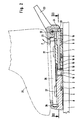
- a bearing plate 2 is fastened on the top of a ski 1, for example by means of screws not shown in the drawing.
- the edges of the bearing plate 2 facing the tip and the rear end of the ski are designed in the form of a circular arc in plan view, both circular arcs having the same curvature and the same center of curvature. Otherwise, the circular-arc-shaped edges of the bearing plate 2 gradually pass into the central region of the bearing plate 2 in the manner shown in FIG. 2, such that the said edges of the bearing plate 2 have a certain vertical distance from the top of the ski 1.
- the bearing plate 2 carries on its top a fixedly arranged in the center of curvature of the circular edges of the bearing plate 2, perpendicular to the ski top 3, which has a pronounced non-circular cross-section and is provided with a plate-like head.
- the pin 3 has between the bearing plate 2 and its plate-like head two facing surfaces, vertical to the top of the ski and parallel to the ski cross axis parallel plane surfaces 4.
- a slideway 5 is arranged, which two symmetrical to the vertical longitudinal plane, relative to each other has obtuse-angled wedge-shaped sections.
- the bearing plate 2 and the pin 3 serve to hold two plate-like base parts 6 and 7. These base parts 6 and 7 are supported with sliding plates 8 on their underside on the upper side of the ski 1.
- the circular arc edges of the bearing plate 2 are arranged recesses which accommodate the circular arc edges of the bearing plate 2 spaced from the top of the ski, such that the base parts 6 and 7 remain displaceable in the longitudinal direction of the ski relative to the bearing plate 2 and with ridges 9 molded onto them are able to reach under the circular arc edges of the bearing plate 2, which are spaced apart from the top of the ski.
- the top of the base parts 6 and 7 is approximately in the same plane as the top of the plate-shaped head of the pin 3. In the vicinity of the pin 3, a recess is formed in the top of the base parts 6 and 7, such that the base parts 6 and 7 den able to reach under the plate-shaped head of the pin 3.
- the plates 10 can be embedded in the material of the base parts 6 and 7.
- the base parts 6 and 7 form a unit which can be pivoted together about the pin 3.
- the transverse distance is less than the diameter of the plate-shaped head of the pin 3.
- the sections of the guide rods 11 protruding to the right from the base part 6 in FIG. 3 pass through bores in the plate 10 of the base part 7 and also adjoining bores 12 arranged in the base part 7, which receive the guide rods 11 without play, but slidably.
- the bores 12 widen in steps in bores 13 which extend to the edge of the base part 7 facing away from the pin 3.
- helical compression springs 14 which are clamped between the step between the bores 12 and 13 on the one hand and on threaded portions of the guide rods 11 screw-adjustable threaded sleeves 15 on the other hand.
- the prestressing of the helical compression springs 14 can be adjusted by a corresponding screw displacement of the threaded sleeves 15 on the guide rods 11.
- the helical compression springs 14 search for the threaded sleeves 15, which are slidably received in the bores 13, to push to the right relative to the base part 7 in FIG. 3. As a result, the base parts 6 and 7 are pressed with their plates 10 against opposite sides of the pin 3.
- a plunger 18 is slidably guided, the end facing the pin 3 cooperates with the slide 5 and the other end protruding into the channel 17 protrudes into a pressure piece 19 which is slidably guided in the channel 17 and one of the non-circular cross-section of the Channel 17 has an adapted cross-section such that the pressure piece 19 is prevented from rotating about the axis of the plunger 18.
- the end face of the pressure piece 19 facing away from the tappet 18 is designed as a flat surface with a notch or step 20 extending in the ski transverse direction.
- a hold-down device 21 is pivotably mounted about an axis 22 parallel to the transverse axis of the base part 7.
- This hold-down device 21 forms, together with an actuating lever 23, a double lever-like part which is provided with a cam 24 which projects downwards.
- This cam 24 protrudes through one slot-like recess on the base part 7 into the channel 17, where the cam 24 rests on the facing end face of the pressure piece 19.
- the cam 24 pushes the pressure piece 19 and thus the plunger 18 relative to the base part 7 to the left, the end of the plunger on the pin side 18 emerges from the assigned opening of the plate 10 of the base part 7 and the base part 7 or its plate 10 forcibly moves away from the facing side of the pin 3.
- the cam 24 engages with the notch or step 20.
- the base part 7 with its plate 10 is moved back towards the pin 3 because the helical compression springs 14 always urge the two base parts 6 and 7 against opposite sides of the pin 3 search.
- the plunger 18 and the pressure piece 19 are displaced relative to the base part 7 in FIG. 2 to the right, the hold-down device 21 being returned to the locking position according to FIG. 2.
- the binding shown serves to accommodate a plate part 26 arranged on the underside of a ski boot 25, which in the normal position of the base parts 6 and 7 shown with the hold-down 21 in the locked position (see FIG. 2) on the top of the base parts 6 and 7 practically free of play is held by positive locking.
- the form fit is effected on the one hand by supporting webs 27 arranged on the longitudinal edges of the base parts 6 and 7, which laterally overlap the longitudinal edges of the shoe-side plate part 26.
- the plate member 26 is prevented from rotating relative to the base members 6 and 7 about an axis perpendicular to the top of the base members 6 and 7.
- the front and rear transverse edges of the plate part 26 are largely immovably held forwards and backwards and upwards by a cross-sectionally claw-shaped stop part 28 at the end of the base part 6 remote from the pin or by the hold-down device 21, as can be seen from FIG. 2.
- the binding shown works as follows: To insert the ski boot 25 or its plate part 26 into the binding, the hold-down device 21 is first brought into its upwardly pivoted release position by depressing its actuating lever 23, which remains set by latching the cam 24 on the notch or step 20 of the pressure piece 19 . In this position of the hold-down 21, the base part 7 is held away from the pin 3 by the plunger 18. The plate 10 of the base part 6 is clamped against the facing flat surface 4 of the pin 3, with the result that the base part 6 and thus also the base part 7 align with their longitudinal axes parallel to the longitudinal axis of the ski 1 or seek to maintain this orientation. The pin-side end of the plunger 18 rests on the rounded wedge tip of the slideway 5.
- the plate member 26 is inserted between the support webs 27 and the stop member 28 and the hold-down 21; this is possible without constraint, because the base part 7 is kept away from the pin 3 and thus also from the base part 6. Then, with the heel region of the ski boot 25 protruding rearward beyond the plate part 26, the hold-down device 21 can be depressed from the release position pivoted in the direction of the arrow P, the cam 24 being lifted out of the locking engagement with the locking notch or step 20 on the pressure piece 19. This unlocking has the result that the compression springs 14 are able to push the base parts 6 and 7 against each other and against opposite sides of the pin 3 until the position shown in FIGS. 1 to 3 is reached.
- the ski boot 25 In the event of a forward fall of the skier, the ski boot 25 tries to stand out from the base part 7 with its heel region (above the hold-down 21). The rear end of the plate part 26 takes the hold-down 21 in the direction of arrow P. With sufficiently large forces, the hold-down device 21 is pivoted so far in the direction of the arrow P, the base part 7 being moved away from the pin 3 and the base part 6 at the same time that the hold-down device 21 can no longer hold the plate part 26. The ski boot 25 is thus released from the binding.
- the ski boot 25 tries to rotate about the axis of the pin 3, the base parts 6 and 7 also being rotated by the interaction of the support webs 27 with the longitudinal edges of the plate part 26.
- the result of this is that the plates 10 of the base parts 6 and 7 which have previously been laid flat on the flat surfaces 4 of the pin 3 assume an inclined position relative to the flat surfaces 4 and can only be supported on diametrically opposed vertical edges of the flat surfaces 4.
- the triggering described last is further facilitated in that the pin-side end of the plunger 18 can increasingly emerge from the associated opening of the plate 10 of the base part 7 when the base parts 6 and 7 are pivoted about the pin 3 due to the shape of the slide 5 on the pin 3 the hold-down device 21 receives a corresponding movement play in the direction of arrow P.
- a hold-down device 21 similar to that of the base part 7 can optionally be arranged on the base part 26 instead of the stop part 28, plunger 18 and pressure piece 19 then being arranged accordingly. This also enables triggering in the case of pure backward falls.
- triggering in the case of pure backward falls can also be made possible in that the stop part 28 engages over the upper side of the shoe-side plate part 26 with an inclined surface rising towards the pin 3. If the tip of the shoe is then lifted off the base part 6 with greater force, a force component occurs in the longitudinal direction of the base part 6 on the said inclined surface, which component increasingly tries to move away from the base part 7.
- cam 24 The ratchet-like interaction of cam 24 and pressure piece 19 can also be achieved by the cam 24 assuming an over-center position in the release position of the hold-down device 21, such that the pressure of the pressure piece 19 acting on the cam 24 causes the hold-down device 21 in the direction of arrow P via the as End position trained release position tries to move.
- the arrangement of the locking notch or step 20 on the pressure piece 19 is unnecessary.
Abstract
Description
Die Erfindung betrifft eine Sicherheitsskibindung zur auslösbaren Halterung eines Skischuhes, mit zwei gemeinsam um einen zur Skioberseite senkrechten, skifesten Zapfen mit unrundem Querschnitt schwenkbaren Basisteilen, die gegen die Kraft eines zwischen ihnen wirksamen, vorspannbaren Federaggregates in Schuhlängsrichtung auseinanderrückbar und vom Federaggregat gegen entgegengesetzte Seiten des Zapfens gespannt sind, welcher aufgrund seines unrunden Querschnittes die Basisteile auseinanderrückt, wenn dieselben aus einer Normallage in eine Schräglage schwenken, und mit an den Basisteilen angeordneten Kupplungselementen, welche in der Normallage der Basisteile formschlüssig sowie im wesentlichen spielfrei mit schuhfesten Gegenkupplungselementen zur skifesten Halterung des Skischuhes zusammenwirken und dessen Gegenkupplungselemente beim Auseinanderrücken der Basisteile zur Auslösung des Skischuhes freigeben, wobei ein an einem Basisteil als Kupplungselement angeordneter, zwischen einer Riegellage und einer verrastbaren Freigabelage in Richtung der Skihochachse beweglicher Niederhalter bei seiner Bewegung in die Freigabelage das eine Basisteil vom anderen Basisteil gegen den Widerstand des Federaggregates, welches die Basisteile in die Normallage und damit den Niederhalter in die Riegellage zurückzustellen sucht, abrückt und aus der verrasteten Freigabelage beim Einsetzen des Skischuhes in die Bindung durch einen Teil des Skischuhes unter Entrastung in Richtung der Riegellage niedertretbar ist, in der der Niederhalter bei Normallage der Basisteile ein Gegenkupplungselement von oben übergreift, sowie mit einem Betätigungsorgan, welches mit dem Niederhalter zu dessen willkürlicher Betätigung zwangsgekoppelt ist.The invention relates to a safety ski binding for releasable mounting of a ski boot, with two base parts which can be pivoted together about a ski-fixed pin with a non-circular cross section which is perpendicular to the top of the ski and which can be pushed apart in the longitudinal direction of the shoe against the force of a spring unit which is effective between them and can be pushed apart by the spring unit against opposite sides of the pin curious, which, due to its non-circular cross-section, moves the base parts apart when they pivot from a normal position into an inclined position, and with coupling elements arranged on the base parts, which in the normal position of the base parts are form-fitting and essentially free of play with shoe-resistant counter-coupling elements for ski-fixed mounting of the Ski boots interact and release its counter-coupling elements when the base parts are pushed apart to trigger the ski boot, a hold-down device arranged on a base part as a coupling element, between a locking position and a lockable release position moving in the direction of the ski vertical axis, moving one base part from the other base part against its movement into the release position the resistance of the spring assembly, which tries to return the base parts to the normal position and thus the hold-down device to the locking position, moves away and from the locked release position when the ski boot is inserted into the binding by a part of the ski boot with release in the direction of the locking position, in which the hold-down device overlaps a counter-coupling element from above in the normal position of the base parts, and with an actuating member which is positively coupled to the hold-down device for its arbitrary actuation.
Eine derartige Sicherheitsskibindung ist aus der französischen Patentanmeldung 77 26029 bekannt, vgl. insbesondere die Fig. 21 bis 23 sowie die zugehörige Beschreibung.Such a safety ski binding is known from French patent application 77 26029, cf. in particular FIGS. 21 to 23 and the associated description.
Bei dieser bekannten Skibindung besitzt der am einen Basisteil angeordnete Niederhalter Nocken, die mit zugeordneten Kulissen am anderen Basisteil zusammenwirken, derart, daß die beiden Basisteile in Freigabelage des Niederhalters durch die Nocken sowie die Kulissenbahnen in einer voneinander abgerückten Lage relativ zueinander gehalten werden. Damit wird das Federaggregat daran gehindert, die Basisteile gegen den skifesten Zapfen anzudrücken, d.h. der durch das Federaggregat normalerweise bewirkte Kraftschluß zwischen den Basisteilen und dem Zapfen wird aufgehoben. Um nun ein unerwünschtes Spiel der Basisteile relativ zum Zapfen zu vermeiden, ist am einen Basisteil ein gesonderter Rastkolben angeordnet, welcher mittels einer gesonderten Feder gegen eine zugewandte abgeflachte Seite des Zapfens gedrängt wird. Auf diese Weise läßt sich eine Stellkraft erzeugen, die die Basisteile in eine Lage zu bringen sucht, bei der die Längsachse der Basisteile parallel zur Skilängsachse verläuft und das dem Kolben gegenüberliegende Basisteil gegen die vom Kolben abgewandte Seite des Zapfens gedrängt wird.In this known ski binding, the hold-down device arranged on one base part has cams, which interact with associated links on the other base part, in such a way that the two base parts are held in a released position relative to one another by the cams and the link tracks in the released position of the hold-down device. This prevents the spring assembly from pressing the base parts against the ski-fixed pin, ie the frictional connection between the base parts and the pin normally caused by the spring unit is canceled. To now To avoid unwanted play of the base parts relative to the pin, a separate locking piston is arranged on a base part, which is pressed by means of a separate spring against a flattened side of the pin facing. In this way, an actuating force can be generated which tries to bring the base parts into a position in which the longitudinal axis of the base parts runs parallel to the longitudinal axis of the ski and the base part opposite the piston is pressed against the side of the pin facing away from the piston.
Diese Konstruktion ist relativ aufwendig, d.h. durch eine Vielzahl relativ zueinander beweglicher Teile wird eine größere Reibung verursacht. Hinzu kommt, daß der Auslösewiderstand der Skibindung nicht allein durch die Vorspannung des Federaggregates, sondern auch durch die Spannung der den Rastkolben beaufschlagenden zusätzlichen Feder beeinflußt wird.This construction is relatively complex, i.e. a large number of moving parts relative to each other causes greater friction. In addition, the triggering resistance of the ski binding is influenced not only by the pretension of the spring assembly, but also by the tension of the additional spring acting on the locking piston.
Aufgabe der Erfindung ist es nun, bei einer Skibindung der eingangs angegebenen Art eine vereinfachte Konstruktion sowie eine verbesserte Handhabung zu erreichen.The object of the invention is now to achieve a simplified construction and improved handling in a ski binding of the type specified at the outset.
Diese Aufgabe wird erfindungsgemäß dadurch gelöst, daß der Niederhalter in seiner Freigabelage das eine Basisteil vom skifesten Zapfen, an dem sich der Niederhalter dabei direkt oder indirekt abstützt, gegen die Kraft des Federaggregates abgerückt hält.This object is achieved in that the hold-down device in its release position keeps a base part from the ski-fixed pin, on which the hold-down device is supported directly or indirectly, against the force of the spring unit.
Erfindungsgemäß ist also vorgesehen, daß der Niederhalter unmittelbar mit an ihm angeordneten Teilen bzw. mittelbar über Übertragungsteile mit dem Zapfen zusammenwirken kann, um das den Niederhalter tragende Basisteil vom Zapfen abzurücken. Dabei bewirkt das Federaggregat, welches zwischen die beiden Basisteile eingespannt ist und dieselben gegeneinanderzuschieben sucht, daß das den Niederhalter tragende eine Basisteil über den Niederhalter bzw. die damit verbundenen oder zusammenwirkenden Teile und das andere Basisteil unmittelbar am Zapfen angedrückt bleiben. Somit bleiben die Basisteile am Zapfen spielfrei gehaltert. Darüber hinaus kann gegebenenfalls ein Drehmoment erzeugt werden, welches die Basisteile in eine gewünschte Ausrichtung relativ zum Ski zu stellen sucht; hierzu ist lediglich erforderlich, daß entweder der Niederhalter bzw. die damit verbundenen oder zusammenwirkenden Teile oder das andere Basisteil vom Federaggregat in Andruck an einer unrunden Fläche des Zapfens gehalten werden.According to the invention, it is therefore provided that the hold-down device can interact directly with parts arranged on it or indirectly via transmission parts with the pin, to move the base part carrying the hold-down device off the pin. The spring assembly, which is clamped between the two base parts and seeks to push them against each other, causes the base part carrying the hold-down element to remain pressed directly onto the pin via the hold-down element or the parts connected or interacting therewith and the other base part. This means that the base parts on the pin remain free of play. In addition, a torque can optionally be generated, which tries to place the base parts in a desired orientation relative to the ski; all that is required for this is that either the hold-down device or the parts connected or interacting therewith or the other base part are held in pressure by the spring assembly on a non-circular surface of the pin.
Aufgrund der erfindungsgemäßen Anordnung besteht gegebenenfalls die Möglichkeit, an beiden Basisteilen ähnliche Niederhalter anzuordnen, welche in ihrer Freigabelage das jeweilige Basisteil vom Zapfen abgerückt halten.Due to the arrangement according to the invention, it is possible, if necessary, to arrange similar hold-down devices on both base parts, which hold the respective base part away from the pin in its release position.
Gemäß einer besonders bevorzugten Ausführungsform der Erfindung kann vorgesehen sein, daß ein am Niederhalter angeordneter Nocken am einen Ende eines Stößels anliegt, der in dem den Niederhalter tragenden Basisteil radial zum Zapfen verschiebbar geführt und dessen anderes Ende auf dem Umfang des Zapfens abgestützt ist. Damit wird eine konstruktiv einfache Möglichkeit geschaffen, den Niederhalter in größerer Entfernung vom Zapfen anzuordnen, derart, daß der Niederhalter mit den Fersenbereichen des Skischuhes - oder auch mit einem Bereich an der Schuhspitze - zusammenwirken kann.According to a particularly preferred embodiment of the invention, it can be provided that a cam arranged on the hold-down device rests against one end of a plunger, which is guided radially displaceably in the base part carrying the hold-down device and the other end of which is supported on the circumference of the pin. This creates a structurally simple way to arrange the hold-down device at a greater distance from the pin, such that the hold-down device with the heel areas of the Ski boots - or also with an area at the toe - can interact.
Des weiteren ist es zweckmäßig, wenn die Basisteile eine den Skischuh vertikal abstützende Platte bilden und die schuhseitigen Gegenkupplungselemente als schuhseitiges Plattenteil ausgebildet sind. In diesem Falle können an den Basisteilen fest angeordnete vertikale Vorsprünge angeordnet sein, die mit den Längsrändern des schuhseitigen Plattenteiles zusammenwirken und damit den Schuh in Schuhquerrichtung formschlüssig festlegen. Um den Schuh in Schuhlängsrichtung sowie gegen Abheben von den Basisteilen zu sichern, kann der zur Schuhspitze hinweisende Rand des schuhseitigen Plattenteiles von vorn und oben durch eine feststehende Klaue od.dgl. am einen Basisteil umgriffen werden, während der zur Ferse des Skischuhs weisende Rand des Plattenteiles vom Niederhalter in entsprechender Weise umfaßt wird. In diesem Falle kann der Niederhalter aus seiner Freigabelage beim Einsetzen des Skischuhes in die Bindung durch den nach hinten über das schuhseitige Plattenteil überstehenden Fersenbereich in die Riegellage niedergetreten werden.Furthermore, it is expedient if the base parts form a plate that vertically supports the ski boot and the shoe-side counter-coupling elements are designed as a shoe-side plate part. In this case, fixedly arranged vertical projections can be arranged on the base parts, which cooperate with the longitudinal edges of the shoe-side plate part and thus positively fix the shoe in the transverse direction of the shoe. In order to secure the shoe in the longitudinal direction of the shoe and to prevent it from being lifted off the base parts, the edge of the shoe-side plate part pointing towards the shoe tip can be secured from the front and above by a fixed claw or the like. can be gripped on a base part, while the edge of the plate part facing the heel of the ski boot is encompassed in a corresponding manner by the hold-down device. In this case, the hold-down device can be depressed from its release position when the ski boot is inserted into the binding through the heel area protruding rearward beyond the shoe-side plate part into the locking position.
Grundsätzlich ist eine entsprechende Anordnung des Niederhalters auch an der Schuhspitze möglich.A corresponding arrangement of the hold-down device is also possible on the toe.
Im übrigen wird bezüglich vorteilhafter Merkmale der Erfindung auf die Ansprüche sowie die nachfolgende Erläuterung einer besonders bevorzugten Ausführungsform verwiesen, die in der Zeichnung dargestellt ist.Otherwise, with regard to advantageous features of the invention, reference is made to the claims and the following explanation of a particularly preferred embodiment, which is shown in the drawing.
Dabei zeigt
- Fig. 1
- eine Draufsicht auf die Skibindung,
- Fig. 2
- einen Längsschnitt entsprechend der Schnittlinie II-II in Fig. 1 und
- Fig. 3
- einen Horizontalschnitt entsprechend der Schnittlinie III-III in Fig. 2.
- Fig. 1
- a top view of the ski binding,
- Fig. 2
- a longitudinal section along the section line II-II in Fig. 1 and
- Fig. 3
- a horizontal section along the section line III-III in Fig. 2nd
Auf der Oberseite eines Skis 1 ist eine Lagerplatte 2 befestigt, beispielsweise mittels in der Zeichnung nicht dargestellter Schrauben. Die der Spitze sowie dem hinteren Ende des Skis zugewandten Ränder der Lagerplatte 2 sind in Draufsicht kreisbogenförmig ausgebildet, wobei beide Kreisbögen gleiche Krümmung und gleiches Krümmungszentrum besitzen. Im übrigen gehen die kreisbogenförmigen Ränder der Lagerplatte 2 in der aus Fig. 2 ersichtlichen Weise stufenartig in den Mittelbereich der Lagerplatte 2 über, derart, daß die genannten Ränder der Lagerplatte 2 einen gewissen vertikalen Abstand von der Oberseite des Skis 1 besitzen.A
Die Lagerplatte 2 trägt auf ihrer Oberseite einen im Krümmungszentrum der kreisbogenförmigen Ränder der Lagerplatte 2 fest angeordneten, zur Skioberseite senkrechten Zapfen 3, welcher einen ausgeprägt unrunden Querschnitt besitzt und mit einem tellerartigen Kopf versehen ist. Dabei besitzt der Zapfen 3 zwischen der Lagerplatte 2 und seinem tellerartigen Kopf zwei voneinander abgewandte, zur Skioberseite vertikale und zur Skiquerachse parallele Planflächen 4. Innerhalb der von der Skispitze abgewandten Planfläche 4 ist eine Gleitbahn 5 angeordnet, welche zwei zur vertikalen Skilängsebene symmetrische, relativ zueinander stumpfwinklig keilförmig angeordnete Abschnitte aufweist.The
Die Lagerplatte 2 sowie der Zapfen 3 dienen zur Halterung zweier plattenartiger Basisteile 6 und 7. Diese Basisteile 6 und 7 sind mit Gleitplatten 8 auf ihrer Unterseite auf der Oberseite des Skis 1 verschiebbar abgestützt. Im übrigen sind auf der Unterseite der Basisteile 6 und 7 den Kreisbogenrändern der Lagerplatte 2 angepaßte Aussparungen angeordnet, die die von der Skioberseite beabstandeten Kreisbogenränder der Lagerplatte 2 aufnehmen, derart, daß die Basisteile 6 und 7 in Skilängsrichtung relativ zur Lagerplatte 2 verschiebbar bleiben und mit ihnen angeformten Stegen 9 die von der Skioberseite beabstandeten Kreisbogenränder der Lagerplatte 2 zu untergreifen vermögen.The
Die Oberseite der Basisteile 6 und 7 liegt in etwa gleicher Ebene wie die Oberseite des tellerförmigen Kopfes des Zapfens 3. In der Umgebung des Zapfens 3 ist in der Oberseite der Basisteile 6 und 7 eine Vertiefung ausgebildet, derart, daß die Basisteile 6 und 7 den tellerförmigen Kopf des Zapfens 3 zu untergreifen vermögen.The top of the
An den dem Zapfen 3 zugewandten Rändern der Basisteile 6 und 7 sind quer zur Längsachse der Basisteile 6 und 7 vertikal angeordnete Platten 10 gehaltert, welche mit den Planflächen 4 des Zapfens 3 zusammenwirkende plane Abstützflächen bilden.At the edges of the
Wenn die Basisteile 6 und 7 aus Kunststoff hergestellt sind, wie es in der Regel zweckmäßig ist, können die Platten 10 in das Material der Basisteile 6 und 7 eingebettet sein. Die Basisteile 6 und 7 bilden eine gemeinsam um den Zapfen 3 schwenkbare Einheit.If the
Zur Verbindung der beiden Basisteile 6 und 7 dienen zwei zur Längsachse der Basisteile 6 und 7 parallele Führungsstangen 11, deren Querabstand geringer als der Durchmesser des tellerförmigen Kopfes des Zapfens 3 ist. Diese zwischen dem tellerförmigen Kopf des Zapfens 3 und der Lagerplatte 2 erstreckten Führungsstangen 11 durchsetzen Bohrungen in der Platte 10 des Basisteiles 6 und sind an ihren in Fig. 3 linken Enden mit an ihnen angeordneten Gewindeabschnitten in entsprechende Gewindebohrungen des Basisteiles 6 fest eingeschraubt. Die aus dem Basisteil 6 in Fig. 3 nach rechts herausstehenden Abschnitte der Führungsstangen 11 durchsetzen Bohrungen in der Platte 10 des Basisteiles 7 sowie daran anschließende, im Basisteil 7 angeordnete Bohrungen 12, welche die Führungsstangen 11 spielfrei, jedoch gleitverschiebbar aufnehmen. Die Bohrungen 12 erweitern sich stufenförmig in Bohrungen 13, welche sich bis zu dem vom Zapfen 3 abgewandten Rand des Basisteiles 7 erstrecken.To connect the two
Innerhalb der Bohrungen 13 sind von den Führungsstangen 11 axial durchsetzte Schraubendruckfedern 14 angeordnet, welche zwischen der Stufe zwischen den Bohrungen 12 und 13 einerseits und auf Gewindeabschnitten der Führungsstangen 11 schraubverstellbaren Gewindehülsen 15 andererseits auf Druck eingespannt sind. Die Vorspannung der Schraubendruckfedern 14 läßt sich durch entsprechende Schraubverschiebung der Gewindehülsen 15 auf den Führungsstangen 11 einstellen.Within the
Die Schraubendruckfedern 14 suchen die Gewindehülsen 15, welche in den Bohrungen 13 verschiebbar aufgenommen sind, relativ zum Basisteil 7 in Fig. 3 nach rechts zu drängen. Dadurch werden die Basisteile 6 und 7 mit ihren Platten 10 gegen entgegengesetzte Seiten des Zapfens 3 angedrückt.The helical compression springs 14 search for the threaded
Zwischen den beiden Bohrungen 12 bzw. 13 ist in Höhe der Gleitbahn 5 des Zapfens 3 eine zu den vorgenannten Bohrungen 12 und 13 parallele weitere Bohrung 16 angeordnet, welche durch eine Öffnung in der Platte 10 des Basisteiles 7 zum Zapfen 3 hin geöffnet ist und sich in Fig. 3 nach rechts stufenförmig in einem im Basisteil 7 angeordneten Kanal 17 mit unrundem Querschnitt erweitert.Between the two
In der Bohrung 16 ist ein Stößel 18 gleitverschiebbar geführt, dessen dem Zapfen 3 zugewandtes Ende mit der Gleitbahn 5 zusammenwirkt und dessen in den Kanal 17 hineinragendes anderes Ende in ein Druckstück 19 hineinragt, welches im Kanal 17 verschiebbar geführt ist und einen dem unrunden Querschnitt des Kanales 17 angepaßten Querschnitt aufweist, derart, daß das Druckstück 19 an einer Drehung um die Achse des Stößels 18 gehindert wird.In the bore 16 a
Die vom Stößel 18 abgewandte Stirnseite des Druckstückes 19 ist als Planfläche mit einer in Skiquerrichtung verlaufenden Rastkerbe bzw. -stufe 20 ausgebildet.The end face of the
An dem vom Zapfen 3 entfernten Ende des Basisteiles 7 ist ein Niederhalter 21 um eine zur Querachse des Basisteiles 7 parallele Achse 22 schwenkbar gelagert. Dieser Niederhalter 21 bildet zusammen mit einem Betätigungshebel 23 ein doppelhebelartiges Teil, welches mit einem nach unten abstehenden Nocken 24 versehen ist. Dieser Nocken 24 ragt durch eine schlitzartige Ausnehmung am Basisteil 7 bis in den Kanal 17 hinein, wo der Nocken 24 auf der zugewandten Stirnseite des Druckstückes 19 aufliegt.At the end of the
Wird der Niederhalter 21 aus seiner in Fig. 2 dargestellten Riegellage entsprechend dem Pfeil P in eine nach aufwärts verschwenkte Freigabelage verstellt, so schiebt der Nocken 24 das Druckstück 19 und damit den Stößel 18 relativ zum Basisteil 7 nach links, wobei das zapfenseitige Ende des Stößels 18 aus der zugeordneten Öffnung der Platte 10 des Basisteiles 7 austritt und das Basisteil 7 bzw. dessen Platte 10 von der zugewandten Seite des Zapfens 3 zwangsweise abrückt. Bei Erreichen der Freigabelage verrastet der Nocken 24 an der Rastkerbe bzw. -stufe 20.If the hold-down
Sobald der Niederhalter 21 aus der verrasteten Freigabelage etwas in Richtung seiner Riegellage zurückgeschwenkt wird, wird das Basisteil 7 mit seiner Platte 10 wieder an den Zapfen 3 herangerückt, weil die Schraubendruckfedern 14 die beiden Basisteile 6 und 7 immer gegen entgegengesetzte Seiten des Zapfens 3 zu drängen suchen. Dabei werden der Stößel 18 sowie das Druckstück 19 relativ zum Basisteil 7 in Fig. 2 nach rechts verschoben, wobei der Niederhalter 21 in die Riegellage gemäß Fig. 2 zurückgestellt wird.As soon as the hold-down
Die dargestellte Bindung dient zur Aufnahme eines auf der Unterseite eines Skischuhes 25 angeordneten Plattenteiles 26, welches in der dargestellten Normallage der Basisteile 6 und 7 bei in Riegellage befindlichem Niederhalter 21 (vgl. Fig. 2) auf der Oberseite der Basisteile 6 und 7 praktisch spielfrei durch Formschluß festgehalten wird. Der Formschluß wird einerseits bewirkt durch an den Längsrändern der Basisteile 6 und 7 angeordnete Abstützstege 27, welche die Längsränder des schuhseitigen Plattenteiles 26 seitlich übergreifen. Damit wird das Plattenteil 26 an einer Drehung relativ zu den Basisteilen 6 und 7 um eine zur Oberseite der Basisteile 6 und 7 senkrechte Achse gehindert. Andererseits werden die vorderen und hinteren Querränder des Plattenteiles 26 von einem im Querschnitt klauenförmigen Anschlagteil 28 am zapfenfernen Ende des Basisteiles 6 bzw. vom Niederhalter 21 am Basisteil 7 nach vorwärts und rückwärts sowie nach oben weitestgehend unbeweglich festgehalten, wie aus Fig. 2 ersichtlich ist.The binding shown serves to accommodate a
Die dargestellte Bindung funktioniert wie folgt:
Zum Einsetzen des Skischuhes 25 bzw. seines Plattenteiles 26 in die Bindung wird zunächst der Niederhalter 21 durch Niederdrücken seines Betätigungshebels 23 in seine nach oben verschwenkte Freigabelage gebracht, die durch Verrastung des Nockens 24 an der Rastkerbe bzw. -stufe 20 des Druckstückes 19 eingestellt bleibt. In dieser Stellung des Niederhalters 21 wird das Basisteil 7 durch den Stößel 18 vom Zapfen 3 abgerückt festgehalten. Dabei wird die Platte 10 des Basisteiles 6 gegen die zugewandte Planfläche 4 des Zapfens 3 gespannt, mit der Folge, daß das Basisteil 6 und damit auch das Basisteil 7 sich mit ihren Längsachsen parallel zur Längsachse des Skis 1 auszurichten bzw. diese Ausrichtung beizuhalten suchen. Dabei liegt das zapfenseitige Ende des Stößels 18 auf der abgerundeten Keilspitze der Gleitbahn 5 auf.The binding shown works as follows:
To insert the
Nun wird das Plattenteil 26 zwischen die Abstützstege 27 sowie das Anschlagteil 28 und den Niederhalter 21 eingesetzt; dies ist zwangsfrei möglich, weil das Basisteil 7 vom Zapfen 3 und damit auch vom Basisteil 6 abgerückt gehalten wird. Sodann kann mit dem nach hinten über das Plattenteil 26 überstehenden Fersenbereich des Skischuhes 25 der Niederhalter 21 aus der in Pfeilrichtung P verschwenkten Freigabelage niedergetreten werden, wobei der Nocken 24 aus dem Rasteingriff mit der Rastkerbe bzw. -stufe 20 am Druckstück 19 ausgehoben wird. Diese Entrastung hat zur Folge, daß die Druckfedern 14 die Basisteile 6 und 7 gegeneinander sowie gegen entgegengesetzte Seiten des Zapfens 3 anzuschieben vermögen, bis die in den Fig. 1 bis 3 dargestellte Lage erreicht ist.Now the
Zum Aussteigen aus der Bindung genügt es, den Betätigungshebel 23 niederzudrücken, wodurch das Basisteil 7 vom Zapfen 3 sowie vom Basisteil 6 abgerückt wird, so daß das Plattenteil 26 des Skischuhes 25 von den Basisteilen 6 und 7 abgehoben werden kann.To get out of the binding, it is sufficient to depress the
Im Falle eines Vorwärtssturzes des Skifahrers sucht sich der Skischuh 25 mit seinem Fersenbereich (oberhalb des Niederhalters 21) vom Basisteil 7 abzuheben. Dabei nimmt das hintere Ende des Plattenteiles 26 den Niederhalter 21 in Pfeilrichtung P mit. Bei hinreichend großen Kräften wird dabei der Niederhalter 21 so weit in Pfeilrichtung P geschwenkt, wobei gleichzeitig das Basisteil 7 vom Zapfen 3 sowie vom Basisteil 6 abgerückt wird, daß der Niederhalter 21 das Plattenteil 26 nicht mehr zu halten vermag. Damit wird der Skischuh 25 aus der Bindung ausgelöst.In the event of a forward fall of the skier, the
Im Falle starker Drehmomente relativ zur Achse der Tibia des Beines des Skiläufers sucht sich der Skischuh 25 um die Achse des Zapfens 3 zu drehen, wobei die Basisteile 6 und 7 durch Zusammenwirken der Abstützstege 27 mit den Längsrändern des Plattenteiles 26 mitgedreht werden. Dies hat zur Folge, daß die zuvor auf den Planflächen 4 des Zapfens 3 flächig angelegten Platten 10 der Basisteile 6 und 7 eine Schräglage zu den Planflächen 4 einnehmen und sich jeweils nur noch an diametral einander gegenüberliegenden Vertikalrändern der Planflächen 4 abzustützen vermögen. Dadurch werden die Platten 10 sowie die Basisteile 6 und 7 voneinander abgerückt, und zwar bei hinreichend weiter Schwenkung der Basisteile 6 und 7 um den Zapfen 3 so weit, daß das Anschlagteil 28 sowie der Niederhalter 21 die hinteren und vorderen Enden des Plattenteiles 26 nicht mehr gleichzeitig von oben zu überlappen vermögen. Damit wird der Skischuh 25 wiederum ausgelöst.In the case of strong torques relative to the axis of the tibia of the skier's leg, the
Die zuletzt beschriebene Auslösung wird noch dadurch erleichtert, daß das zapfenseitige Ende des Stößels 18 bei Schwenkung der Basisteile 6 und 7 um den Zapfen 3 aufgrund der Form der Gleitbahn 5 am Zapfen 3 zunehmend aus der zugeordneten Öffnung der Platte 10 des Basisteiles 7 austreten kann und der Niederhalter 21 ein entsprechendes Bewegungsspiel in Pfeilrichtung P erhält.The triggering described last is further facilitated in that the pin-side end of the
Auf diese Weise wird bei sogenannten kombinierten Stürzen, d.h. bei einem Vorwärtssturz mit gleichzeitiger Torsionsbeanspruchung der Tibia des Skiläufers einer Überbeanspruchung der Fuß- und Beingelenke entgegengewirkt.In this way, in the case of so-called combined falls, ie a forward fall with simultaneous torsional stress on the tibia of the skier, an overuse of the foot and leg joints is counteracted.
Abweichend von der in der Zeichnung dargestellten Ausführungsform kann gegebenenfalls anstelle des Anschlagteiles 28 am Basisteil 26 ein ähnlicher Niederhalter 21 wie am Basisteil 7 angeordnet sein, wobei dann auch Stößel 18 und Druckstück 19 entsprechend angeordnet sind. Damit wird auch eine Auslösung bei reinen Rückwärtsstürzen ermöglicht.In a departure from the embodiment shown in the drawing, a hold-down
Gegebenenfalls kann eine Auslösung bei reinen Rückwärtsstürzen auch dadurch ermöglicht werden, daß das Anschlagteil 28 die Oberseite des schuhseitigen Plattenteiles 26 mit einer zum Zapfen 3 hin ansteigenden Schrägfläche übergreift. Wenn dann die Schuhspitze mit größerer Kraft vom Basisteil 6 abgehoben wird, tritt an der genannten Schrägfläche eine Kraftkomponente in Längsrichtung des Basisteiles 6 auf, welches dabei vom Basisteil 7 zunehmend abzurücken sucht.If necessary, triggering in the case of pure backward falls can also be made possible in that the
Das rastgesperreartige Zusammenwirken von Nocken 24 und Druckstück 19 kann auch erreicht werden, indem der Nocken 24 in der Freigabelage des Niederhalters 21 eine Übertotpunktlage einnimmt, derart, daß der auf den Nocken 24 wirkende Druck des Druckstückes 19 den Niederhalter 21 in Pfeilrichtung P über die als Endlage ausgebildete Freigabelage hinauszubewegen sucht. In diesem Falle erübrigt sich die Anordnung der Rastkerbe bzw. -stufe 20 am Druckstück 19.The ratchet-like interaction of
Claims (17)
daß der Niederhalter (21) in seiner Freigabelage das eine Basisteil (7) vom Zapfen (3), an dem sich der Niederhalter (21) dabei direkt oder indirekt abstützt, gegen die Kraft des Federaggregates (14) abgerückt hält.Safety ski binding for releasable mounting of a ski boot (25) with
that the hold-down device (21) in its release position keeps the one base part (7) from the pin (3), on which the hold-down device (21) is supported directly or indirectly, against the force of the spring assembly (14).
dadurch gekennzeichnet, daß der Niederhalter (21) als um eine zur Skioberseite etwa parallele Achse (22) schwenkbarer Hebel ausgebildet ist.Safety ski binding according to claim 1,
characterized in that the hold-down device (21) is designed as a lever which can be pivoted about an axis (22) which is approximately parallel to the upper side of the ski.
dadurch gekennzeichnet, daß Niederhalter (21) und Betätigungssorgan (23) einen Doppelhebel bilden.Safety ski binding according to claim 2,
characterized in that the hold-down device (21) and the actuating member (23) form a double lever.
dadurch gekennzeichnet, daß ein am Niederhalter (21) angeordneter Nocken (24), der am Umfang des Zapfens (3) bzw. an einem daran abgestützten Teil (18,19) anliegt, in Freigabelage des Niederhalters (21) das eine Basisteil (7) in vom Zapfen (3) und damit auch vom anderen Basisteil (6) abgerückter Lage hält.Safety ski binding according to claim 2 or 3,
characterized in that a cam (24) arranged on the hold-down device (21), which bears against the circumference of the pin (3) or against a part (18, 19) supported thereon, in the release position of the hold-down device (21), the one base part (7 ) in the position away from the pin (3) and thus also from the other base part (6).
dadurch gekennzeichnet, daß der Nocken (24) am einen Ende (Druckstück 19) eines im einen Basisteil (7) radial zum Zapfen (3) verschiebbar geführten Stößels (18) anliegt, dessen anderes Ende auf dem Umfang (Gleitbahn 5) des Zapfens (3) abgestützt ist.Safety ski binding according to claim 4,
characterized in that the cam (24) bears against one end (thrust piece 19) of a plunger (18) which is displaceably guided radially to the pin (3) in a base part (7), the other end of which rests on the circumference (slideway 5) of the pin ( 3) is supported.
dadurch gekennzeichnet, daß die mit dem Nocken (24) zusammenwirkende Stirnfläche des Stößels (18) bzw. eines damit verbundenen Teiles (Druckstück 19) eine Rastvertiefung bzw. -stufe (20) aufweist, an der sich der Nocken (24) in Freigabelage des Niederhalters (21) verrasten läßt.Safety ski binding according to claim 5,
characterized in that the end face of the tappet (18) or a part (pressure piece 19) cooperating with the cam (24) has a locking recess or step (20) on which the cam (24) is in the release position of the Hold down retainer (21).
dadurch gekennzeichnet, daß der Stößel (18) bzw. das die Rastvertiefung bzw. -stufe (20) aufweisende Teil (19) zur Längsachse des Stößels (18) undrehbar geführt sind.Safety ski binding according to claim 6,
characterized in that the plunger (18) or the part (19) having the latching recess or step (20) are non-rotatably guided to the longitudinal axis of the plunger (18).
dadurch gekennzeichnet, daß der Nocken (24) in Freigabelage des Niederhalters (21) durch das Federaggregat (14) in einer Übertotpunktlage gehalten wird.Safety ski binding according to one of claims 4 to 7,
characterized in that, in the release position of the hold-down device (21), the cam (24) is held in an over-center position by the spring unit (14).
dadurch gekennzeichnet, daß am einen Basisteil (6) fest angeordnete Führungsstangen (11) im anderen Basisteil (7) längsverschiebbar geführt sind, daß die Führungsstangen (11) Druckfedern (14) axial durchsetzen, die jeweils zwischen einem vom Zapfen (3) entfernten stangenseitigen Widerlagerteil (Gewindehülse 15) und einem vom Zapfen (3) weniger weit beabstandeten Widerlager (Stufe) am anderen Basisteil (7) eingespannt sind.Safety ski binding according to one of claims 1 to 8,
characterized in that on one base part (6) fixedly arranged guide rods (11) are guided so as to be longitudinally displaceable in the other base part (7), that the guide rods (11) axially penetrate compression springs (14), each between a rod-side distance from the pin (3) Abutment part (threaded sleeve 15) and an abutment (step) less distant from the pin (3) are clamped on the other base part (7).
dadurch gekennzeichnet, daß die stangenseitigen Widerlagerteile (15) auf einem Gewindeabschnitt der zugeordneten Führungsstangen (11) schraubverstellbar angeordnet sind, derart, daß die Druckspannung der Druckfedern (14) veränderbar ist.Safety ski binding according to claim 9,
characterized in that the rod-side abutment parts (15) are arranged so as to be screw-adjustable on a threaded section of the associated guide rods (11) such that the compressive stress of the compression springs (14) can be changed.
dadurch gekennzeichnet, daß die stangenseitigen Widerlagerteile (15) mit den jeweiligen Führungsstangen (11) fest verbunden und die Führungsstangen (11) mit Gewindeabschnitten in Gewindebohrungen am einen Basisteil (6) schraubverstellbar angeordnet sind, derart, daß die Druckspannung der Druckfedern (14) veränderbar ist.Safety ski binding according to claim 9,
characterized in that the rod-side abutment parts (15) are fixedly connected to the respective guide rods (11) and the guide rods (11) are arranged so as to be screw-adjustable with threaded sections in threaded bores on a base part (6) such that the compressive stress of the compression springs (14) can be changed is.
dadurch gekennzeichnet, daß die Basisteile (6,7) eine den Skischuh (25) vertikal abstützende Platte bilden.Safety ski binding according to one of claims 1 to 11,
characterized in that the base parts (6, 7) form a plate which vertically supports the ski boot (25).
dadurch gekennzeichnet, daß die schuhseitigen Gegenkupplungselemente durch ein schuhseitiges Plattenteil (26) gebildet werden, dessen Rand mit den Kupplungselementen (27,28) bzw. dem Niederhalter (21) zusammenwirken, wobei der Niederhalter (21) sowie ein relativ zum Plattenteil (26) diametral gegenüberliegendes Kupplungselement (Anschlagteil 28) den Rand des Plattenteiles (26) von oben zu übergreifen vermögen.Safety ski binding according to one of claims 1 to 12,
characterized in that the shoe-side counter-coupling elements are formed by a shoe-side plate part (26), the edge of which cooperate with the coupling elements (27, 28) or the hold-down device (21), the hold-down device (21) and a part relative to the plate part (26) diametrically opposite coupling element (stop part 28) can overlap the edge of the plate part (26) from above.
dadurch gekennzeichnet, daß das Plattenteil (26) in Draufsicht kleiner als der Skischuh (25) ist und der Skischuh (25) das Plattenteil (26) zumindest im Bereich des Niederhalters (21) überragt, derart, daß der Niederhalter (21) von dem ihn überragenden Teil des Skischuhes (25) beim Einstieg in die Bindung zwangsweise aus der Freigabelage in Richtung der Riegellage niedergetreten wird.Safety ski binding according to one of claims 1 to 13,
characterized in that the plate part (26) is smaller in plan view than the ski boot (25) and the ski boot (25) projects beyond the plate part (26) at least in the area of the hold-down device (21), in such a way that the hold-down device (21) from the the protruding part of the ski boot (25) is forced to step down from the release position in the direction of the locking position when entering the binding.
dadurch gekennzeichnet, daß der Niederhalter (21) unter der Ferse des Skischuhes (25) angeordnet ist.Safety ski binding according to one of claims 1 to 14,
characterized in that the hold-down device (21) is arranged under the heel of the ski boot (25).
dadurch gekennzeichnet, daß zwei funktional gleichartige Niederhalter (21) angeordnet sind, die am Skischuh (25) unter der Ferse sowie unter den Zehen angreifen.Safety ski binding according to one of claims 1 to 15,
characterized in that two functionally similar hold-down devices (21) are arranged which engage the ski boot (25) under the heel and under the toes.
dadurch gekennzeichnet, daß der Niederhalter (21) bzw. die den Niederhalter (21) am Zapfen (3) abstützenden Teile (Stößel 18) mit einer zapfenseitigen Gleitbahn (5) zusammenwirken, welche derart geformt ist, daß die Riegellage des Niederhalters (21) bei Schwenkung der Basisteile (6,7) aus ihrer Normallage mit zunehmendem Spiel abgestützt wird.Safety ski binding according to one of claims 1 to 16,
characterized in that the hold-down device (21) or the parts (plunger 18) supporting the hold-down device (21) on the pin (3) cooperate with a pin-side slideway (5) which is shaped such that the locking position of the hold-down device (21) when pivoting the base parts (6,7) from their normal position is supported with increasing play.
Applications Claiming Priority (2)
| Application Number | Priority Date | Filing Date | Title |
|---|---|---|---|
| DE4005254 | 1990-02-20 | ||
| DE4005254A DE4005254C2 (en) | 1990-02-20 | 1990-02-20 | Safety ski binding for the releasable mounting of a ski boot |
Publications (3)
| Publication Number | Publication Date |
|---|---|
| EP0443108A2 true EP0443108A2 (en) | 1991-08-28 |
| EP0443108A3 EP0443108A3 (en) | 1991-11-13 |
| EP0443108B1 EP0443108B1 (en) | 1994-08-03 |
Family
ID=6400538
Family Applications (1)
| Application Number | Title | Priority Date | Filing Date |
|---|---|---|---|
| EP90122245A Expired - Lifetime EP0443108B1 (en) | 1990-02-20 | 1990-11-22 | Safety ski binding with element for releasing the ski boot |
Country Status (5)
| Country | Link |
|---|---|
| US (1) | US5116074A (en) |
| EP (1) | EP0443108B1 (en) |
| JP (1) | JP3009491B2 (en) |
| AT (1) | ATE109365T1 (en) |
| DE (2) | DE4005254C2 (en) |
Cited By (1)
| Publication number | Priority date | Publication date | Assignee | Title |
|---|---|---|---|---|
| FR2780296A1 (en) * | 1998-06-26 | 1999-12-31 | Salomon Sa | Boot binding for snowboard |
Families Citing this family (6)
| Publication number | Priority date | Publication date | Assignee | Title |
|---|---|---|---|---|
| US5505477A (en) * | 1993-07-19 | 1996-04-09 | K-2 Corporation | Snowboard binding |
| US5971420A (en) * | 1994-06-06 | 1999-10-26 | Shimano, Inc. | Snowboard binding |
| US6145868A (en) * | 1997-05-16 | 2000-11-14 | The Burton Corporation | Binding system for an article used to glide on snow |
| US5941553A (en) * | 1997-09-15 | 1999-08-24 | Korman; Nathan M. | Boot binding apparatus for a snowboard |
| FR2793155B1 (en) * | 1999-05-03 | 2001-06-22 | Look Fixations Sa | SNAP-ON FIXING FOR THE SLIDING BOARD |
| DE102013009762A1 (en) * | 2013-06-10 | 2014-12-11 | Andreas Allmann | Sicherheitsskibindungssystem |
Citations (2)
| Publication number | Priority date | Publication date | Assignee | Title |
|---|---|---|---|---|
| FR2400923A1 (en) * | 1977-08-26 | 1979-03-23 | Beyl Jean Joseph Alfred | Low profile safety ski binding - has housing with internal flexible system and external holder |
| DE2923416A1 (en) * | 1978-06-27 | 1980-01-10 | Suhner Intertrade Ag | SKI BINDING WITH A LATCHED AXLE, LOCKED CONSOLE |
Family Cites Families (7)
| Publication number | Priority date | Publication date | Assignee | Title |
|---|---|---|---|---|
| FR1587912A (en) * | 1968-09-06 | 1970-04-03 | ||
| AT311229B (en) * | 1971-03-12 | 1973-11-12 | Smolka & Co Wiener Metall | Ski binding |
| AT325485B (en) * | 1973-06-07 | 1975-10-27 | Smolka & Co Wiener Metall | RELEASE SKI BINDING |
| US4182524A (en) * | 1977-08-26 | 1980-01-08 | Look S.A. | Safety ski binding |
| DE2749904A1 (en) * | 1977-11-08 | 1979-05-10 | Gerhard Dr Welzel | Ski safety binding with hooks - has adjustable elasticity restraining tendency of skier to topple in any direction |
| FR2410447A1 (en) * | 1977-12-02 | 1979-06-29 | Beyl Jean Joseph Alfred | SKI BOOT |
| FR2430777A1 (en) * | 1978-07-13 | 1980-02-08 | Look Sa | SHOE AND SKI BINDING ASSEMBLY |
-
1990
- 1990-02-20 DE DE4005254A patent/DE4005254C2/en not_active Expired - Fee Related
- 1990-11-22 AT AT90122245T patent/ATE109365T1/en not_active IP Right Cessation
- 1990-11-22 DE DE59006703T patent/DE59006703D1/en not_active Expired - Fee Related
- 1990-11-22 EP EP90122245A patent/EP0443108B1/en not_active Expired - Lifetime
-
1991
- 1991-02-12 US US07/653,967 patent/US5116074A/en not_active Expired - Fee Related
- 1991-02-18 JP JP3023431A patent/JP3009491B2/en not_active Expired - Lifetime
Patent Citations (2)
| Publication number | Priority date | Publication date | Assignee | Title |
|---|---|---|---|---|
| FR2400923A1 (en) * | 1977-08-26 | 1979-03-23 | Beyl Jean Joseph Alfred | Low profile safety ski binding - has housing with internal flexible system and external holder |
| DE2923416A1 (en) * | 1978-06-27 | 1980-01-10 | Suhner Intertrade Ag | SKI BINDING WITH A LATCHED AXLE, LOCKED CONSOLE |
Cited By (1)
| Publication number | Priority date | Publication date | Assignee | Title |
|---|---|---|---|---|
| FR2780296A1 (en) * | 1998-06-26 | 1999-12-31 | Salomon Sa | Boot binding for snowboard |
Also Published As
| Publication number | Publication date |
|---|---|
| JP3009491B2 (en) | 2000-02-14 |
| JPH04218183A (en) | 1992-08-07 |
| DE4005254C2 (en) | 2001-06-21 |
| DE59006703D1 (en) | 1994-09-08 |
| EP0443108A3 (en) | 1991-11-13 |
| EP0443108B1 (en) | 1994-08-03 |
| ATE109365T1 (en) | 1994-08-15 |
| US5116074A (en) | 1992-05-26 |
| DE4005254A1 (en) | 1991-08-22 |
Similar Documents
| Publication | Publication Date | Title |
|---|---|---|
| EP2608853B1 (en) | Rear binding for touring with dynamic sliding range | |
| EP1954360B1 (en) | Ski binding | |
| EP1559455B1 (en) | Binding for a touring ski | |
| DE102012201812B4 (en) | Front unit for a sliding board binding, touring binding and ski jumping binding | |
| EP0351881A2 (en) | Binding coupled to skibootleg adjustment | |
| EP0295372A1 (en) | Laterally releasable front jaw for safety skibinding | |
| EP3581248A1 (en) | Heelholder | |
| EP3345659B1 (en) | Automated heelholder device for a ski binding | |
| DE2927059A1 (en) | SKI SHOE WITH INTEGRATED SKI TIE | |
| EP0394513B1 (en) | Safety ski binding | |
| DE2757723C2 (en) | ||
| EP0443108B1 (en) | Safety ski binding with element for releasing the ski boot | |
| DE2758658A1 (en) | SKI BRAKE | |
| DE2528578A1 (en) | SAFETY BINDING FOR SKI BOOTS | |
| EP1795236B1 (en) | Ski bindings | |
| DE3035738A1 (en) | SKI BRAKE | |
| DE3151222A1 (en) | FRONT JAWS FOR A SAFETY SKI BINDING | |
| EP0128243B1 (en) | Releasable ski binding | |
| DE2159638C3 (en) | Toe piece for safety ski bindings | |
| DE3924211A1 (en) | SKI BOOTS SAFETY SKI BINDING ARRANGEMENT | |
| WO1990001358A1 (en) | Ski safety binding | |
| DE3725482A1 (en) | FRICTION PLATE WITH AUTOMATIC CENTERING FOR MONOBLOCK SECURITY BINDING | |
| AT526522B1 (en) | Toe piece and safety ski binding with a toe piece | |
| EP0438659B1 (en) | Releasable binding | |
| DE4121777C2 (en) | Ski brake |
Legal Events
| Date | Code | Title | Description |
|---|---|---|---|
| PUAI | Public reference made under article 153(3) epc to a published international application that has entered the european phase |
Free format text: ORIGINAL CODE: 0009012 |
|
| AK | Designated contracting states |
Kind code of ref document: A2 Designated state(s): AT CH DE FR IT LI |
|
| PUAL | Search report despatched |
Free format text: ORIGINAL CODE: 0009013 |
|
| AK | Designated contracting states |
Kind code of ref document: A3 Designated state(s): AT CH DE FR IT LI |
|
| 17P | Request for examination filed |
Effective date: 19911216 |
|
| 17Q | First examination report despatched |
Effective date: 19930318 |
|
| ITF | It: translation for a ep patent filed |
Owner name: LENZI & C. |
|
| GRAA | (expected) grant |
Free format text: ORIGINAL CODE: 0009210 |
|
| AK | Designated contracting states |
Kind code of ref document: B1 Designated state(s): AT CH DE FR IT LI |
|
| REF | Corresponds to: |
Ref document number: 109365 Country of ref document: AT Date of ref document: 19940815 Kind code of ref document: T |
|
| REF | Corresponds to: |
Ref document number: 59006703 Country of ref document: DE Date of ref document: 19940908 |
|
| ET | Fr: translation filed | ||
| PLBE | No opposition filed within time limit |
Free format text: ORIGINAL CODE: 0009261 |
|
| STAA | Information on the status of an ep patent application or granted ep patent |
Free format text: STATUS: NO OPPOSITION FILED WITHIN TIME LIMIT |
|
| REG | Reference to a national code |
Ref country code: FR Ref legal event code: TP |
|
| 26N | No opposition filed | ||
| PGFP | Annual fee paid to national office [announced via postgrant information from national office to epo] |
Ref country code: CH Payment date: 19951129 Year of fee payment: 6 |
|
| PG25 | Lapsed in a contracting state [announced via postgrant information from national office to epo] |
Ref country code: LI Effective date: 19961130 Ref country code: CH Effective date: 19961130 |
|
| REG | Reference to a national code |
Ref country code: CH Ref legal event code: PL |
|
| PGFP | Annual fee paid to national office [announced via postgrant information from national office to epo] |
Ref country code: FR Payment date: 20041118 Year of fee payment: 15 |
|
| PGFP | Annual fee paid to national office [announced via postgrant information from national office to epo] |
Ref country code: AT Payment date: 20041122 Year of fee payment: 15 |
|
| PGFP | Annual fee paid to national office [announced via postgrant information from national office to epo] |
Ref country code: DE Payment date: 20050128 Year of fee payment: 15 |
|
| PG25 | Lapsed in a contracting state [announced via postgrant information from national office to epo] |
Ref country code: IT Free format text: LAPSE BECAUSE OF NON-PAYMENT OF DUE FEES;WARNING: LAPSES OF ITALIAN PATENTS WITH EFFECTIVE DATE BEFORE 2007 MAY HAVE OCCURRED AT ANY TIME BEFORE 2007. THE CORRECT EFFECTIVE DATE MAY BE DIFFERENT FROM THE ONE RECORDED. Effective date: 20051122 Ref country code: AT Free format text: LAPSE BECAUSE OF NON-PAYMENT OF DUE FEES Effective date: 20051122 |
|
| PG25 | Lapsed in a contracting state [announced via postgrant information from national office to epo] |
Ref country code: DE Free format text: LAPSE BECAUSE OF NON-PAYMENT OF DUE FEES Effective date: 20060601 |
|
| PG25 | Lapsed in a contracting state [announced via postgrant information from national office to epo] |
Ref country code: FR Free format text: LAPSE BECAUSE OF NON-PAYMENT OF DUE FEES Effective date: 20060731 |
|
| REG | Reference to a national code |
Ref country code: FR Ref legal event code: ST Effective date: 20060731 |