EP0443104A1 - Terminal module for local network - Google Patents
Terminal module for local network Download PDFInfo
- Publication number
- EP0443104A1 EP0443104A1 EP90121781A EP90121781A EP0443104A1 EP 0443104 A1 EP0443104 A1 EP 0443104A1 EP 90121781 A EP90121781 A EP 90121781A EP 90121781 A EP90121781 A EP 90121781A EP 0443104 A1 EP0443104 A1 EP 0443104A1
- Authority
- EP
- European Patent Office
- Prior art keywords
- base part
- coupling unit
- bus coupling
- adapter
- connection unit
- Prior art date
- Legal status (The legal status is an assumption and is not a legal conclusion. Google has not performed a legal analysis and makes no representation as to the accuracy of the status listed.)
- Granted
Links
Images

Classifications
-
- H—ELECTRICITY
- H02—GENERATION; CONVERSION OR DISTRIBUTION OF ELECTRIC POWER
- H02G—INSTALLATION OF ELECTRIC CABLES OR LINES, OR OF COMBINED OPTICAL AND ELECTRIC CABLES OR LINES
- H02G3/00—Installations of electric cables or lines or protective tubing therefor in or on buildings, equivalent structures or vehicles
- H02G3/02—Details
- H02G3/08—Distribution boxes; Connection or junction boxes
- H02G3/16—Distribution boxes; Connection or junction boxes structurally associated with support for line-connecting terminals within the box
-
- H—ELECTRICITY
- H01—ELECTRIC ELEMENTS
- H01R—ELECTRICALLY-CONDUCTIVE CONNECTIONS; STRUCTURAL ASSOCIATIONS OF A PLURALITY OF MUTUALLY-INSULATED ELECTRICAL CONNECTING ELEMENTS; COUPLING DEVICES; CURRENT COLLECTORS
- H01R9/00—Structural associations of a plurality of mutually-insulated electrical connecting elements, e.g. terminal strips or terminal blocks; Terminals or binding posts mounted upon a base or in a case; Bases therefor
- H01R9/22—Bases, e.g. strip, block, panel
- H01R9/24—Terminal blocks
- H01R9/2425—Structural association with built-in components
-
- H—ELECTRICITY
- H01—ELECTRIC ELEMENTS
- H01R—ELECTRICALLY-CONDUCTIVE CONNECTIONS; STRUCTURAL ASSOCIATIONS OF A PLURALITY OF MUTUALLY-INSULATED ELECTRICAL CONNECTING ELEMENTS; COUPLING DEVICES; CURRENT COLLECTORS
- H01R13/00—Details of coupling devices of the kinds covered by groups H01R12/70 or H01R24/00 - H01R33/00
- H01R13/46—Bases; Cases
- H01R13/502—Bases; Cases composed of different pieces
- H01R13/512—Bases; Cases composed of different pieces assembled by screw or screws
Definitions
- the invention relates to a connection unit of the type specified in the preamble of claim 1.
- EP 0 344 609 A2 discloses a digital signal transmission system for home automation technology in which data telegrams can be transmitted between different connection units installed in the building or between each connection unit and a central unit.
- the data is transmitted for the purpose of switching, controlling, regulating, measuring and / or monitoring, it being possible for the connection units to have the functions of input and / or output units.
- External electrical devices, detectors or function transmitters can be connected to the connection units.
- the connection unit enables the external device to communicate with the house control system.
- function-specific connection units for different external devices are required, it is provided to standardize the system to be installed in the building that each connection unit consists of a bus coupling unit and an adapter.
- bus coupling units are constructed identically to one another, so that when the system is installed, only one bus coupling unit that contains a microprocessor must be installed at each connection point.
- This bus coupling unit is connected to a function-specific adapter, which completes the connection unit and gives it the behavior that is required for communication with a specific external device type.
- connection unit consisting of bus coupling unit and adapter.
- the invention has for its object to provide a connection unit of the type specified in the preamble of claim 1, which is simple in construction and enables the attachment of the adapter selected from a number of different available adapter types and which is particularly easy to assemble.
- connection unit has a base part which is to be mounted separately on a wall and carries the bus coupling unit.
- the adapter can be attached to this base part on the side next to the bus coupling unit.
- Bus coupling unit and adapter are thus arranged side by side and their mutual connection takes place inside the base part through connecting lines provided there.
- the connecting cables are part of the base part.
- the bus coupling unit on the other hand, can be permanently attached to the base part or can also be exchangeably or pluggably mounted. In the case of a fixed attachment, fixed wiring of the bus coupling unit is provided by soldering or also by screwing the electrical connections, while replaceable or detachable attachment is to be understood as meaning a plug connection.
- such a plug connection is provided between the base part and the adapter.
- the adapter only has to be plugged onto the base part in order to establish the electrical connection between the adapter and the connecting lines, and thus also to the bus coupling unit.
- the mechanical attachment can then be carried out by additionally screwing on the housing part containing the adapter.
- connection unit is a surface-mounted device that is mounted on a wall.
- the connection unit When installing the house control system in the building, initially only the basic parts are installed and each connected with the associated data cable.
- the adapters are only mounted on the base parts before the house control system is started up. Depending on the function to be carried out by the connection unit, the relevant adapter type is selected.
- the base parts (and also the bus coupling units), however, are the same for all connection units.
- connection unit according to the invention can be designed to be moisture and dust-tight, all of which electrical components are housed in tightly fitting interiors.
- the bus coupling unit can either be accommodated in a separate housing part which can be detachably attached to the base part, but it can also be an integral part of the base part.
- the detachable fastening of the bus coupling unit has the advantage that it can be replaced easily in the event of a defect.
- the adapter must not only be replaceable in the rare cases of a defect. Since the adapter is a function-specific part, a certain type of adapter must be used depending on the function of the external device. For this reason, if the external device has to perform other or additional functions, the adapter must be replaced.
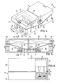
- the connection unit of FIGS. 1 to 6 has a base part 10, which is designed in the manner of a rectangular trough and a closed, i.e. has opening-free, bottom wall 11 and side walls 12 and 13.
- the front side walls 13 are higher than the side walls 12 and contain cable passage openings 14 with screw threads for inserting sealing screw plugs (not shown) which enable a moisture-tight cable passage.
- the side walls 12 are oblique and their height decreases steadily towards the longitudinal center of the base part 10. In the longitudinal center of the base part 10 there is an intermediate wall 25 connecting the side walls 12, which divides the interior of the base part into two separate interior spaces 15 and 16.
- the two housing parts 17 and 18 are placed on the base part 10 as a cover, the housing part 17 covering the interior 15 and the housing part 18 covering the interior 16 and sealing off from the outside.
- the housing parts 17 and 18 are open at the bottom.
- the adapter 19 is located in the housing part 17 and the bus coupling unit 20 is in each case in a casting compound in the housing part 18.
- the bus coupling unit 20 is one on one Printed circuit board housed electrical circuit, which contains, among other things, a microprocessor and can exchange data telegrams with other connection units or with a central unit.
- the adapter 19 can also contain a microprocessor, but it can also contain, for example, only a relay or an electronic switch if it is designed for a very simple function.
- Adapter 19 and bus coupling unit 20 contain all electrical components of the connection unit.
- the housing parts 17 and 18 are generally identical to one another, but they should have a constructive identifier which can be used to prevent one of the housing parts from being placed on the wrong interior.
- the housing parts 17 and 18 have side walls 21 with inclined lower edges and different height end walls 22 and 23, so that when they are placed as a lid on the base part 10, together with the base part they form a substantially rectangular housing, the length of which is approximately twice as long is as big as its width.
- seal 24 On the upper side of the side walls 12 and 13 of the base part 10 runs a seal 24 which surrounds the interiors 15 and 16 all around.
- This seal 24 has a sealing strip 24a resting on the intermediate wall 25.
- the sealing strip 24a has such a width that the lower edges of the high end walls 22 of both housing parts 17 and 18 can rest on it.
- plug connectors 30 which protrude from the floor 11 and are each connected in one piece to a cable connection device 31 (FIG. 3). These plug connectors are inserted into corresponding receiving devices 31a molded onto the base 11.
- the female connectors 30 are each arranged in a row.
- male connectors 32 protruding from the respective housing part 17 or 18 are provided in the form of flattened pins, which are also arranged in a row and which are placed on the base part when the respective housing part 17, 18 is placed 10 come into contact with the connectors 30.
- two data cables 33 and 34 which are connected with their wires to cable connection devices 31, pass through the cable passage openings 14 leading into the interior 16.
- the data cable 33 is used for the communication of the bus coupling unit 20 with other connection units or a central unit.
- the wires of the cable 34 are connected to the wires of the data cable 33 by internal connections between the cable connection devices 30.
- the data cable 34 is used to connect one another connection unit or to continue the data cable 33.
- the cable 35 is used to connect an external device, e.g. a light, a detector, thermostats and the like, and the cable 36 is a supply cable.
- connection unit When installing the connection unit in a house control system, the base part 10 is attached to a wall and the data lines 33 and 34 are connected to the relevant cable connector 31 of the interior 16. Then the housing part 18 can be put on and thus the interior 16 hermetically sealed. The other interior 15 can initially be temporarily covered with an empty housing part. The cables 35 and 36 are connected to the cable connection devices 31 of the interior 15. Before the house control system is put into operation, a housing part 17, which contains a corresponding adapter type, is placed on the base part and screwed over the interior 15. The connection unit is then complete and ready for operation.
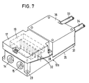
- the housing part 17 containing the adapter 19 with the plug connectors 32 is provided on the base part 10a.
- the bus coupling unit is permanently accommodated in the base part 10a.
- the relevant part of the base part 10a is designed as a plate 35, on which the bus coupling unit is attached and which is covered with a hood 36.
- This hood 36 can be removed for connecting the data cable 33, 34.
- the gap between the plate 35 and the hood 36 is sealed with a separate seal 37.
- the embodiment of Fig. 7 corresponds to the first embodiment, i.e. Connecting lines 37 run in the base part 10a and connect the bus coupling unit to the plug connectors 30, which engage with the plug connectors 32 in the interior 15.
- the bus coupling unit is not connected to the internal connecting lines via plug connectors.
Abstract
Description
Die Erfindung betrifft eine Anschlußeinheit der im Oberbegriff des Patentanspruchs 1 angegebenen Art.The invention relates to a connection unit of the type specified in the preamble of
Aus EP 0 344 609 A2 ist ein digitales Signalübertragungssystem für die Hausleittechnik bekannt, bei dem Datentelegramme zwischen verschiedenen im Gebäude installierten AnschluBeinheiten oder zwischen jeder Anschlußeinheit und einer Zentraleinheit übertragen werden können. Die Datenübertragung erfolgt zum Zwecke des Schaltens, Steuerns, Regelns, Messens und/oder Überwachens, wobei die Anschlußeinheiten die Funktionen von Eingabe- und/oder Ausgabeeinheiten haben können. An die Anschlußeinheiten können externe elektrische Geräte, Melder oder Funktionsgeber angeschlossen werden. Die Anschlußeinheit ermöglicht die Kommunikation des externen Gerätes mit dem Hausleitsystem. Da für unterschiedliche externe Geräte funktionsspezifische Anschlußeinheiten benötigt werden, ist zur Vereinheitlichung des in dem Gebäude zu installierenden Systems vorgesehen, daß jede Anschlußeinheit aus einer Busankopplungs-Einheit und einem Adapter besteht. Die Busankopplungs-Einheiten sind hardware-mäßig untereinander gleich aufgebaut, so daß bei der Installation des Systems an jeder Anschlußstelle zunächst nur eine Busankopplungs-Einheit, die einen Mikroprozessor enthält, zu installieren ist. Diese Busankopplungs-Einheit wird mit einem funktionsspezifischen Adapter verbunden, der die Anschlußeinheit komplettiert und ihr dasjenige Verhalten vermittelt, das für die Kommunikation mit einem bestimmten externen Gerätetyp erforderlich ist.EP 0 344 609 A2 discloses a digital signal transmission system for home automation technology in which data telegrams can be transmitted between different connection units installed in the building or between each connection unit and a central unit. The data is transmitted for the purpose of switching, controlling, regulating, measuring and / or monitoring, it being possible for the connection units to have the functions of input and / or output units. External electrical devices, detectors or function transmitters can be connected to the connection units. The connection unit enables the external device to communicate with the house control system. As function-specific connection units for different external devices are required, it is provided to standardize the system to be installed in the building that each connection unit consists of a bus coupling unit and an adapter. In terms of hardware, the bus coupling units are constructed identically to one another, so that when the system is installed, only one bus coupling unit that contains a microprocessor must be installed at each connection point. This bus coupling unit is connected to a function-specific adapter, which completes the connection unit and gives it the behavior that is required for communication with a specific external device type.
Die vorliegende Erfindung befaßt sich mit der konstruktiven Gestaltung der Anschlußeinheit aus Busankopplungs-Einheit und Adapter. Der Erfindung liegt die Aufgabe zugrunde, eine Anschlußeinheit der im Oberbegriff des Patentanspruchs 1 angegebenen Art zu schaffen, die einfach aufgebaut ist und die Anbringung des aus einer Reihe unterschiedlicher verfügbarer Adaptertypen ausgewählten Adapters ermöglicht und die insbesondere einfach zu montieren ist.The present invention is concerned with the structural design of the connection unit consisting of bus coupling unit and adapter. The invention has for its object to provide a connection unit of the type specified in the preamble of
Die Lösung dieser Aufgabe erfolgt erfindungsgemäß mit den im Patentanspruch 1 angegebenen Merkmalen.This object is achieved according to the invention with the features specified in
Die erfindungsgemäße Anschlußeinheit weist ein Basisteil auf, das separat auf einer Wand zu montieren ist und die Busankopplungs-Einheit trägt. An diesem Basisteil kann seitlich neben der Busankopplungs-Einheit der Adapter befestigt werden. Busankopplungs-Einheit und Adapter sind also nebeneinander angeordnet und ihre gegenseitige Verbindung erfolgt im Innern des Basisteils durch dort vorgesehene Verbindungsleitungen. Die Verbindungsleitungen sind Bestandteil des Basisteils. Die Busankopplungs-Einheit kann dagegen fest an dem Basisteil angebracht oder auch auswechselbar bzw. steckbar montiert sein. Bei fester Anbringung ist eine feste Verdrahtung der Busankopplungs-Einheit durch Löten oder auch durch Verschrauben der elektrischen Anschlüsse vorgesehen, während unter auswechselbarer oder lösbarer Anbringung bzgl. der elektrischen Kontaktgabe eine Steckverbindung zu verstehen ist. Eine solche Steckverbindung ist jedenfalls zwischen Basisteil und Adapter vorgesehen. Dies bedeutet, daß der Adapter lediglich auf das Basisteil aufgesteckt werden muß, um die elektrische Verbindung zwischen Adapter und den Verbindungsleitungen, und somit auch zur Busankopplungs-Einheit herzustellen. Die mechanische Befestigung kann anschließend noch durch zusätzliches Anschrauben des den Adapter enthaltenden Gehäuseteils erfolgen.The connection unit according to the invention has a base part which is to be mounted separately on a wall and carries the bus coupling unit. The adapter can be attached to this base part on the side next to the bus coupling unit. Bus coupling unit and adapter are thus arranged side by side and their mutual connection takes place inside the base part through connecting lines provided there. The connecting cables are part of the base part. The bus coupling unit, on the other hand, can be permanently attached to the base part or can also be exchangeably or pluggably mounted. In the case of a fixed attachment, fixed wiring of the bus coupling unit is provided by soldering or also by screwing the electrical connections, while replaceable or detachable attachment is to be understood as meaning a plug connection. In any case, such a plug connection is provided between the base part and the adapter. This means that the adapter only has to be plugged onto the base part in order to establish the electrical connection between the adapter and the connecting lines, and thus also to the bus coupling unit. The mechanical attachment can then be carried out by additionally screwing on the housing part containing the adapter.
Die erfindungsgemäße Anschlußeinheit ist ein Aufputz-Gerät, das auf einer Wand montiert wird. Bei der Montage des Hausleitsystems in dem Gebäude werden zunächst nur die Basisteile installiert und jeweils mit dem zugehörigen Datenkabel verbunden. Erst vor Inbetriebnahme des Hausleitsystems werden die Adapter an den Basisteilen montiert. Je nach Funktion, die von der Anschlußeinheit ausgeführt werden soll, wird der betreffende Adaptertyp ausgewählt. Die Basisteile (und auch die Busankopplungs-Einheiten) sind dagegen für sämtliche Anschlußeinheiten gleich.The connection unit according to the invention is a surface-mounted device that is mounted on a wall. When installing the house control system in the building, initially only the basic parts are installed and each connected with the associated data cable. The adapters are only mounted on the base parts before the house control system is started up. Depending on the function to be carried out by the connection unit, the relevant adapter type is selected. The base parts (and also the bus coupling units), however, are the same for all connection units.
Die erfindungsgemäße Anschlußeinheit kann feuchtigkeits-und staubdicht ausgebildet sein, wobei sämtliche elektrischen Komponenten in dicht abschließenden Innenräumen untergebracht sind.The connection unit according to the invention can be designed to be moisture and dust-tight, all of which electrical components are housed in tightly fitting interiors.
Die Busankopplungs-Einheit kann entweder in einem separaten Gehäuseteil untergebracht sein, das an dem Basisteil lösbar zu befestigen ist, sie kann aber auch fester Bestandteil des Basisteils sein. Die lösbare Befestigung der Busankopplungs-Einheit hat den Vorteil, daß im Falle eines Defekts auf einfache Weise eine Auswechslung vorgenommen werden kann. Dagegen muß der Adapter nicht nur in den seltenen Fällen eines Defekts ausgewechselt werden können. Da der Adapter ein funktionsspezifisches Teil ist, muß entsprechend der jeweiligen Funktion des externen Geräts ein bestimmter Adaptertyp eingesetzt werden. Wenn das externe Gerät andere oder zusätzliche Funktionen ausführen muß, ist aus diesem Grund eine Auswechslung des Adapters erforderlich.The bus coupling unit can either be accommodated in a separate housing part which can be detachably attached to the base part, but it can also be an integral part of the base part. The detachable fastening of the bus coupling unit has the advantage that it can be replaced easily in the event of a defect. On the other hand, the adapter must not only be replaceable in the rare cases of a defect. Since the adapter is a function-specific part, a certain type of adapter must be used depending on the function of the external device. For this reason, if the external device has to perform other or additional functions, the adapter must be replaced.
Im folgenden werden unter Bezugnahme auf die Zeichnungen Ausführungsbeispiele der Erfindung näher erläutert.Exemplary embodiments of the invention are explained in more detail below with reference to the drawings.
Es zeigen:
- Fig. 1
- eine Explosionsdarstellung einer ersten Ausführungsform der Anschlußeinheit,
- Fig. 2
- eine Draufsicht auf das Basisteil von Fig. 1,
- Fig. 3
- eine Explosionsdarstellung der Kabelverbinder mit den zugehörigen Steckverbindern im vergrößerten Maßstab,
- Fig. 4
- die fertig montierte Anschlußeinheit,
- Fig. 5
- einen Schnitt entlang der Linie V-V von Fig. 4,
- Fig. 6
- einen Schnitt entlang der Linie VI-VI von Fig. 5, und
- Fig. 7
- eine perspektivische Darstellung einer zweiten Ausführungsform.
- Fig. 1
- an exploded view of a first embodiment of the connection unit,
- Fig. 2
- 2 shows a plan view of the base part from FIG. 1,
- Fig. 3
- an exploded view of the cable connector with the associated connectors on an enlarged scale,
- Fig. 4
- the fully assembled connection unit,
- Fig. 5
- 3 shows a section along the line VV from FIG. 4,
- Fig. 6
- a section along the line VI-VI of Fig. 5, and
- Fig. 7
- a perspective view of a second embodiment.
Die Anschlußeinheit der Fign. 1 bis 6 weist ein Basisteil 10 auf, das nach Art einer rechteckigen Wanne ausgebildet ist und eine geschlossene, d.h. öffnungsfreie, Bodenwand 11 sowie Seitenwände 12 und 13 aufweist. Die stirnseitigen Seitenwände 13 sind höher als die Seitenwände 12 und enthalten Kabeldurchtrittsöffnungen 14 mit Schraubgewinden zum Einsetzen abdichtender (nicht dargestellter) Schraubstopfen, die einen feuchtigkeitsdichten Kabeldurchtritt ermöglichen. Die Seitenwände 12 sind schräg und ihre Höhe verringert sich stetig zur Längsmitte des Basisteils 10 hin. In der Längsmitte des Basisteils 10 verläuft eine die Seitenwände 12 verbindende Zwischenwand 25, die das Innere des Basisteils in zwei voneinander getrennte Innenräume 15 und 16 unterteilt.The connection unit of FIGS. 1 to 6 has a
Die beiden Gehäuseteile 17 und 18 werden als Deckel auf das Basisteil 10 aufgesetzt, wobei das Gehäuseteil 17 den Innenraum 15 und das Gehäuseteil 18 den Innenraum 16 bedeckt und nach außen abschließt. Die Gehäuseteile 17 und 18 sind nach unten offen. Im Gehäuseteil 17 befindet sich der Adapter 19 und im Gehäuseteil 18 die Busankopplungs-Einheit 20 jeweils in einer Vergußmasse. Die Busankopplungs-Einheit 20 ist eine auf einer Leiterplatine untergebrachte elektrische Schaltung, die u.a. einen Mikroprozessor enthält und Datentelegramme mit anderen Anschlußeinheiten oder mit einer Zentraleinheit austauschen kann. Der Adapter 19 kann ebenfalls einen Mikroprozessor enthalten, jedoch kann er auch beispielsweise nur ein Relais oder einen elektronischen Schalter enthalten, wenn er für eine sehr einfache Funktion ausgebildet ist. Adapter 19 und Busankopplungs-Einheit 20 enthalten alle elektrischen Komponenten der Anschlußeinheit.The two
Die Gehäuseteile 17 und 18 sind generell untereinander gleich ausgebildet, jedoch sollten sie eine konstruktive Kennung aufweisen, mit der verhindert werden kann, daß eines der Gehäuseteile auf den falschen Innenraum aufgesetzt wird. Die Gehäuseteile 17 und 18 haben Seitenwände 21 mit schrägverlaufenden Unterkanten sowie unterschiedlich hohe Stirnwände 22 und 23, so daß sie, wenn sie als Deckel auf das Basisteil 10 aufgesetzt werden, zusammen mit dem Basisteil ein im wesentlichen rechteckiges Gehäuse bilden, dessen Länge etwa doppelt so groß ist wie seine Breite.The
Auf der Oberseite der Seitenwände 12 und 13 des Basisteils 10 verläuft eine Dichtung 24, die die Innenräume 15 und 16 lückenlos umlaufend umschließt. Diese Dichtung 24 weist einen auf der Zwischenwand 25 aufliegenden Dichtstreifen 24a auf. Der Dichtstreifen 24a hat eine solche Breite, daß auf ihm die Unterkanten der hohen Stirnwände 22 beider Gehäuseteile 17 und 18 aufliegen können.On the upper side of the
Durch miteinander fluchtende Bohrungen 26 in den Gehäuseteilen 17 und 18 sowie 27 im Basisteil 10 sind die Gehäuseteile mit Schrauben 28 am Basisteil 10 befestigt. Die mit Innengewinde versehenen Bohrungen 27 sind in Bereichen außerhalb der Dichtung 24 angeordnet.Through
Weitere Bohrungen 29 am Basisteil 10, die ebenfalls außerhalb des von der Dichtung 24 umschlossenen Bereichs liegen, dienen zur Befestigung des Basisteils an einer Wand.Further bores 29 on the
Im Innenraum 15 sind klemmenförmige Steckverbinder 30 angeordnet, die vom Boden 11 aus aufragen und jeweils einstückig mit einem Kabelanschlußvorrichtung 31 verbunden sind (Fig. 3). Diese Steckverbinder sind in entsprechende, dem Boden 11 angeformte Aufnahmevorrichtungen 31a eingesetzt. Die weiblichen Steckverbinder 30 sind jeweils in einer Reihe angeordnet. An dem Adapter 19 und an der Busankopplungs-Einheit 20 sind aus dem jeweiligen Gehäuseteil 17 bzw. 18 herausragende männliche Steckverbinder 32 in Form abgeflachter Stifte vorgesehen, die ebenfalls in einer Reihe angeordnet sind und die beim Aufsetzen des jeweiligen Gehäuseteils 17,18 auf das Basisteil 10 mit den Steckverbindern 30 in Kontakt kommen.In the interior 15 there are clamp-shaped
Durch die in den Innenraum 16 hineinführenden Kabeldurchtrittsöffnungen 14 führen gemäß Fig. 1 zwei Datenkabel 33 und 34 hindurch, die mit ihren Adern an Kabelanschlußvorrichtungen 31 angeschlossen sind. Das Datenkabel 33 dient für die Kommunikation der Busankopplungs-Einheit 20 mit anderen Anschlußeinheiten oder einer Zentraleinheit. Die Adern des Kabels 34 sind durch interne Verbindungen zwischen den Kabelanschlußvorrichtungen 30 mit den Adern des Datenkabels 33 verbunden. Das Datenkabel 34 dient zum Anschluß einer anderen Anschlußeinheit bzw. zur Weiterführung des Datenkabels 33.According to FIG. 1, two
In den adapterseitigen Innenraum 15 führen zwei Kabel 35 und 36 hinein. Das Kabel 35 dient zum Anschluß eines externen Geräts, z.B. einer Leuchte, eines Melders, Thermostaten u.dgl., und das Kabel 36 ist ein Versorgungskabel.Two
Durch Anstecken der Gehäuseteile 17 und 18 an das Basisteil 10 werden die Verbindungen zwischen den Datenkabeln 33,34 und der Busankopplungs-Einheit 20 sowie die Verbindungen zwischen den Kabeln 35,36 und dem Adapter 19 hergestellt. Damit der Adapter 19 und die Busankopplungs-Einheit 20 miteinander kommunizieren können, sind einige Steckverbinder 30 des Innenraums 15 mit entsprechenden Steckverbindern 30 des Innenraums 16 durch Verbindungsleitungen 37 verbunden.By connecting the
Bei der Installation der Anschlußeinheit in einem Hausleitsystem wird das Basisteil 10 an einer Wand befestigt und die Datenleitungen 33 und 34 werden an die betreffenden Kabelverbinder 31 des Innenraums 16 angeschlossen. Dann kann das Gehäuseteil 18 aufgesetzt und damit der Innenraum 16 hermetisch verschlossen werden. Der andere Innenraum 15 kann zunächst provisorisch mit einem leeren Gehäuseteil abgedeckt werden. An die Kabelanschlußvorrichtungen 31 des Innenraums 15 werden die Kabel 35 und 36 angeschlossen. Vor Inbetriebnahme des Hausleitsystems wird ein Gehäuseteil 17, das einen entsprechenden Adaptertyp enthält, über dem Innenraum 15 auf das Basisteil aufgesetzt und verschraubt. Die Anschlußeinheit ist dann komplettiert und betriebsfähig.When installing the connection unit in a house control system, the
Bei dem Ausführungsbeispiel von Fig. 7 ist auf dem Basisteil 10a nur das den Adapter 19 mit den Steckverbindern 32 enthaltende Gehäuseteil 17 vorgesehen. Die Busankopplungs-Einheit ist im Basisteil 10a fest untergebracht. Der betreffende Teil des Basisteils 10a ist als Platte 35 ausgebildet, auf der die Busankopplungs-Einheit angebracht ist und die mit einer Haube 36 bedeckt ist. Diese Haube 36 kann für den Anschluß der Datenkabel 33,34 abgenommen werden. Der Spalt zwischen der Platte 35 und der Haube 36 ist mit einer separaten Dichtung 37 abgedichtet. Im übrigen entspricht das Ausführungsbeispiel von Fig. 7 dem ersten Ausführungsbeispiel, d.h. im Basisteil 10a verlaufen Verbindungsleitungen 37, die die Busankopplungs-Einheit mit den Steckverbindern 30 verbinden, welche mit den Steckverbindern 32 im Innenraum 15 zusammengreifen. Die Busankopplungs-Einheit ist jedoch nicht über Steckverbinder mit den internen Verbindungsleitungen verbunden.In the embodiment of FIG. 7, only the
Claims (8)
dadurch gekennzeichnet,
daß ein auf einer Wand zu befestigendes Basisteil (10) vorgesehen ist, welches die Busankopplungs-Einheit (20) trägt und auf dem das den Adapter (19) enthaltende Gehäuse (17) lösbar befestigt ist, daß das Basisteil (10) Steckverbinder (30) zum Zusammenstecken mit Steckverbindern (32) des Adapters (19) aufweist und daß in dem Basisteil (10) Verbindungsleitungen (37) von den Steckverbindern (30) des Basisteils zu der Busankopplungs-Einheit (20) verlaufen.Connection unit for the home automation system, with a bus coupling unit (20) which can be connected to a data cable (33) and which contains a microprocessor, and a function-specific adapter (19) which is accommodated in a housing part (17) and can be connected to the bus coupling unit ,
characterized,
that a base part (10) to be fastened to a wall is provided, which carries the bus coupling unit (20) and on which the housing (17) containing the adapter (19) is detachably fastened, that the base part (10) plug connector (30 ) for plugging together with plug connectors (32) of the adapter (19) and that connecting lines (37) run in the base part (10) from the plug connectors (30) of the base part to the bus coupling unit (20).
Priority Applications (1)
| Application Number | Priority Date | Filing Date | Title |
|---|---|---|---|
| AT90121781T ATE102751T1 (en) | 1990-02-17 | 1990-11-14 | CONNECTION UNIT FOR HOME MANAGEMENT. |
Applications Claiming Priority (2)
| Application Number | Priority Date | Filing Date | Title |
|---|---|---|---|
| DE4005086 | 1990-02-17 | ||
| DE4005086A DE4005086A1 (en) | 1990-02-17 | 1990-02-17 | Building data line terminal block |
Publications (2)
| Publication Number | Publication Date |
|---|---|
| EP0443104A1 true EP0443104A1 (en) | 1991-08-28 |
| EP0443104B1 EP0443104B1 (en) | 1994-03-09 |
Family
ID=6400431
Family Applications (1)
| Application Number | Title | Priority Date | Filing Date |
|---|---|---|---|
| EP90121781A Expired - Lifetime EP0443104B1 (en) | 1990-02-17 | 1990-11-14 | Terminal module for local network |
Country Status (3)
| Country | Link |
|---|---|
| EP (1) | EP0443104B1 (en) |
| AT (1) | ATE102751T1 (en) |
| DE (2) | DE4005086A1 (en) |
Cited By (5)
| Publication number | Priority date | Publication date | Assignee | Title |
|---|---|---|---|---|
| EP0532783A1 (en) * | 1991-09-19 | 1993-03-24 | Werner Retzlaff | Box with sockets |
| EP0552780A1 (en) * | 1992-01-21 | 1993-07-28 | Siemens Solar GmbH | Electrical junction box |
| US5274527A (en) * | 1991-08-22 | 1993-12-28 | Werner Retzlaff | Housing with plug-in connections |
| FR2698492A1 (en) * | 1992-11-20 | 1994-05-27 | Itw Fastex Italia Spa | Mains plug for electrical domestic appliance such as washing machine - has base unit receptor with protruding trough section for integrated electricity supply cable and connector |
| WO1996015569A1 (en) * | 1994-11-15 | 1996-05-23 | Aeg Niederspannungstechnik Gmbh | Device for connecting electrical-installation apparatuses |
Families Citing this family (12)
| Publication number | Priority date | Publication date | Assignee | Title |
|---|---|---|---|---|
| US5632647A (en) * | 1994-10-17 | 1997-05-27 | Lucent Technologies Inc. | RF/power tap |
| DE19716137C1 (en) * | 1997-04-17 | 1998-10-22 | Siemens Ag | Module for connecting actuators and / or sensors |
| DE19731883A1 (en) * | 1997-07-24 | 1999-01-28 | Abb Patent Gmbh | Electrical device with devices for connection to a bus system |
| DE19742525C1 (en) * | 1997-09-26 | 1998-11-26 | Reinhard Wiesemann | Interface for connecting electrical sensor or actuator to bus circuit |
| DE19816170C5 (en) * | 1998-04-09 | 2004-09-23 | Sew-Eurodrive Gmbh & Co | control module |
| DE19816719A1 (en) * | 1998-04-16 | 1999-10-21 | Abb Patent Gmbh | Electrical installation instrument for connection at bus system of building |
| DE19905952C2 (en) * | 1999-02-12 | 2001-04-05 | Sew Eurodrive Gmbh & Co | Distribution box |
| DE20203436U1 (en) * | 2002-03-02 | 2003-07-17 | Weidmueller Interface | Passive distributor with several sockets, for connecting sensors or actuators to a bus, has electronic housing of same width for fitting onto underside of distributor housing |
| DE102005015310B4 (en) * | 2005-04-01 | 2008-05-29 | Sew-Eurodrive Gmbh & Co. Kg | device |
| DE102005015320B4 (en) * | 2005-04-01 | 2007-09-27 | Sew-Eurodrive Gmbh & Co. Kg | device |
| DE102005062420A1 (en) | 2005-12-27 | 2007-07-05 | Vega Grieshaber Kg | Electronic insert arrangement for measuring device e.g. pressure measuring device, housing, has injection part and rails arranged to couple module to insert so that distance between interfaces remains constant, when insert is displaced |
| DE102021116738A1 (en) | 2021-06-29 | 2022-12-29 | Götz Joachim Aumüller | Assembly support device |
Citations (4)
| Publication number | Priority date | Publication date | Assignee | Title |
|---|---|---|---|---|
| DE1792650U (en) * | 1959-01-12 | 1959-07-30 | Licentia Gmbh | HOUSING FOR ENERGY CONTROLLER FOR ELECTRICAL ADDITIONAL HEATING. |
| DE7932309U1 (en) * | 1979-11-15 | 1980-04-30 | Kurt Wolf & Co Kg, 7547 Wildbad | Antenna amplifiers for radio and / or television receiving systems |
| GB2105134A (en) * | 1981-09-04 | 1983-03-16 | Philips Nv | Distribution system for a local area network |
| GB2190253A (en) * | 1986-05-05 | 1987-11-11 | Emerson Electric Co | Terminating heater cables sealed junction box |
-
1990
- 1990-02-17 DE DE4005086A patent/DE4005086A1/en not_active Withdrawn
- 1990-11-14 DE DE90121781T patent/DE59004927D1/en not_active Expired - Fee Related
- 1990-11-14 EP EP90121781A patent/EP0443104B1/en not_active Expired - Lifetime
- 1990-11-14 AT AT90121781T patent/ATE102751T1/en not_active IP Right Cessation
Patent Citations (4)
| Publication number | Priority date | Publication date | Assignee | Title |
|---|---|---|---|---|
| DE1792650U (en) * | 1959-01-12 | 1959-07-30 | Licentia Gmbh | HOUSING FOR ENERGY CONTROLLER FOR ELECTRICAL ADDITIONAL HEATING. |
| DE7932309U1 (en) * | 1979-11-15 | 1980-04-30 | Kurt Wolf & Co Kg, 7547 Wildbad | Antenna amplifiers for radio and / or television receiving systems |
| GB2105134A (en) * | 1981-09-04 | 1983-03-16 | Philips Nv | Distribution system for a local area network |
| GB2190253A (en) * | 1986-05-05 | 1987-11-11 | Emerson Electric Co | Terminating heater cables sealed junction box |
Cited By (5)
| Publication number | Priority date | Publication date | Assignee | Title |
|---|---|---|---|---|
| US5274527A (en) * | 1991-08-22 | 1993-12-28 | Werner Retzlaff | Housing with plug-in connections |
| EP0532783A1 (en) * | 1991-09-19 | 1993-03-24 | Werner Retzlaff | Box with sockets |
| EP0552780A1 (en) * | 1992-01-21 | 1993-07-28 | Siemens Solar GmbH | Electrical junction box |
| FR2698492A1 (en) * | 1992-11-20 | 1994-05-27 | Itw Fastex Italia Spa | Mains plug for electrical domestic appliance such as washing machine - has base unit receptor with protruding trough section for integrated electricity supply cable and connector |
| WO1996015569A1 (en) * | 1994-11-15 | 1996-05-23 | Aeg Niederspannungstechnik Gmbh | Device for connecting electrical-installation apparatuses |
Also Published As
| Publication number | Publication date |
|---|---|
| EP0443104B1 (en) | 1994-03-09 |
| ATE102751T1 (en) | 1994-03-15 |
| DE59004927D1 (en) | 1994-04-14 |
| DE4005086A1 (en) | 1991-08-22 |
Similar Documents
| Publication | Publication Date | Title |
|---|---|---|
| EP0443104B1 (en) | Terminal module for local network | |
| DE19738772B4 (en) | plug-in device | |
| DE4438804C1 (en) | Modular control system with bus conductor e.g. B. for building automation | |
| EP0710064B1 (en) | Field bus connection module | |
| EP0452658A1 (en) | Connection unit for domestic applications | |
| DE4437316C2 (en) | Decentralized input / output module for electronic controls | |
| EP0909898A2 (en) | Compressed air maintenance unit | |
| EP0715386A1 (en) | Enclosure for electrical or electronic components | |
| EP0091031B1 (en) | Intermediary plug | |
| DE3708902A1 (en) | CONTROL UNIT FOR ELECTROHYDRAULIC EXTENSION CONTROLS | |
| EP0662741B1 (en) | Low voltage switchgear | |
| EP0049517B1 (en) | Case with drawer for communication engineering apparatus | |
| DE202004011226U1 (en) | Individual control unit for shield extension | |
| DE19836457C1 (en) | Door system, especially door intercom system | |
| EP0669794A1 (en) | Enclosure with a main body and a cover | |
| DE10353469A1 (en) | Electrical connector | |
| DE60223336T2 (en) | Branch connection for electrical module devices | |
| DE3608589C2 (en) | Connector housing | |
| EP0180856A2 (en) | Electrical apparatus | |
| DE19602156C1 (en) | Terminal plug for connecting cable fibres to electric device esp. bus terminal plug | |
| EP3430875B1 (en) | Electronic terminal block for a data bus | |
| DE3231690C2 (en) | Electrical connection terminal for printed circuit boards | |
| EP0442046B1 (en) | Terminal module for local network | |
| DE2340773A1 (en) | Transfer plug connector for wiring system with spring strip - has terminal pins protruding above wiring plane for connection to respective cct. boards | |
| EP2214416B1 (en) | Patch panel and method for its installation |
Legal Events
| Date | Code | Title | Description |
|---|---|---|---|
| PUAI | Public reference made under article 153(3) epc to a published international application that has entered the european phase |
Free format text: ORIGINAL CODE: 0009012 |
|
| AK | Designated contracting states |
Kind code of ref document: A1 Designated state(s): AT BE CH DE DK ES FR GB GR IT LI NL SE |
|
| 17P | Request for examination filed |
Effective date: 19910928 |
|
| 17Q | First examination report despatched |
Effective date: 19930208 |
|
| GRAA | (expected) grant |
Free format text: ORIGINAL CODE: 0009210 |
|
| AK | Designated contracting states |
Kind code of ref document: B1 Designated state(s): AT BE CH DE DK ES FR GB GR IT LI NL SE |
|
| PG25 | Lapsed in a contracting state [announced via postgrant information from national office to epo] |
Ref country code: SE Free format text: THE PATENT HAS BEEN ANNULLED BY A DECISION OF A NATIONAL AUTHORITY Effective date: 19940309 Ref country code: GR Free format text: LAPSE BECAUSE OF FAILURE TO SUBMIT A TRANSLATION OF THE DESCRIPTION OR TO PAY THE FEE WITHIN THE PRESCRIBED TIME-LIMIT Effective date: 19940309 Ref country code: ES Free format text: THE PATENT HAS BEEN ANNULLED BY A DECISION OF A NATIONAL AUTHORITY Effective date: 19940309 Ref country code: DK Effective date: 19940309 Ref country code: BE Effective date: 19940309 |
|
| REF | Corresponds to: |
Ref document number: 102751 Country of ref document: AT Date of ref document: 19940315 Kind code of ref document: T |
|
| ITF | It: translation for a ep patent filed |
Owner name: ING. A. GIAMBROCONO & C. S.R.L. |
|
| GBT | Gb: translation of ep patent filed (gb section 77(6)(a)/1977) |
Effective date: 19940314 |
|
| REF | Corresponds to: |
Ref document number: 59004927 Country of ref document: DE Date of ref document: 19940414 |
|
| ET | Fr: translation filed | ||
| PG25 | Lapsed in a contracting state [announced via postgrant information from national office to epo] |
Ref country code: LI Effective date: 19941130 Ref country code: CH Effective date: 19941130 |
|
| PLBE | No opposition filed within time limit |
Free format text: ORIGINAL CODE: 0009261 |
|
| STAA | Information on the status of an ep patent application or granted ep patent |
Free format text: STATUS: NO OPPOSITION FILED WITHIN TIME LIMIT |
|
| 26N | No opposition filed | ||
| REG | Reference to a national code |
Ref country code: CH Ref legal event code: PL |
|
| PGFP | Annual fee paid to national office [announced via postgrant information from national office to epo] |
Ref country code: GB Payment date: 19961024 Year of fee payment: 7 |
|
| PGFP | Annual fee paid to national office [announced via postgrant information from national office to epo] |
Ref country code: AT Payment date: 19961125 Year of fee payment: 7 |
|
| PGFP | Annual fee paid to national office [announced via postgrant information from national office to epo] |
Ref country code: NL Payment date: 19961129 Year of fee payment: 7 |
|
| PG25 | Lapsed in a contracting state [announced via postgrant information from national office to epo] |
Ref country code: GB Free format text: LAPSE BECAUSE OF NON-PAYMENT OF DUE FEES Effective date: 19971114 Ref country code: AT Free format text: LAPSE BECAUSE OF NON-PAYMENT OF DUE FEES Effective date: 19971114 |
|
| PG25 | Lapsed in a contracting state [announced via postgrant information from national office to epo] |
Ref country code: NL Free format text: LAPSE BECAUSE OF NON-PAYMENT OF DUE FEES Effective date: 19980601 |
|
| GBPC | Gb: european patent ceased through non-payment of renewal fee |
Effective date: 19971114 |
|
| NLV4 | Nl: lapsed or anulled due to non-payment of the annual fee |
Effective date: 19980601 |
|
| PGFP | Annual fee paid to national office [announced via postgrant information from national office to epo] |
Ref country code: FR Payment date: 20031118 Year of fee payment: 14 |
|
| PGFP | Annual fee paid to national office [announced via postgrant information from national office to epo] |
Ref country code: DE Payment date: 20031210 Year of fee payment: 14 |
|
| PG25 | Lapsed in a contracting state [announced via postgrant information from national office to epo] |
Ref country code: DE Free format text: LAPSE BECAUSE OF NON-PAYMENT OF DUE FEES Effective date: 20050601 |
|
| PG25 | Lapsed in a contracting state [announced via postgrant information from national office to epo] |
Ref country code: FR Free format text: LAPSE BECAUSE OF NON-PAYMENT OF DUE FEES Effective date: 20050729 |
|
| REG | Reference to a national code |
Ref country code: FR Ref legal event code: ST |
|
| PG25 | Lapsed in a contracting state [announced via postgrant information from national office to epo] |
Ref country code: IT Free format text: LAPSE BECAUSE OF NON-PAYMENT OF DUE FEES;WARNING: LAPSES OF ITALIAN PATENTS WITH EFFECTIVE DATE BEFORE 2007 MAY HAVE OCCURRED AT ANY TIME BEFORE 2007. THE CORRECT EFFECTIVE DATE MAY BE DIFFERENT FROM THE ONE RECORDED. Effective date: 20051114 |