EP0442819B1 - Optimierungsverfahren der Einspritzung für das Wiederaufstarten einer mit Kraftstoff eingespritzten Brennkraftmaschine - Google Patents
Optimierungsverfahren der Einspritzung für das Wiederaufstarten einer mit Kraftstoff eingespritzten Brennkraftmaschine Download PDFInfo
- Publication number
- EP0442819B1 EP0442819B1 EP19910400390 EP91400390A EP0442819B1 EP 0442819 B1 EP0442819 B1 EP 0442819B1 EP 19910400390 EP19910400390 EP 19910400390 EP 91400390 A EP91400390 A EP 91400390A EP 0442819 B1 EP0442819 B1 EP 0442819B1
- Authority
- EP
- European Patent Office
- Prior art keywords
- engine
- stoppage
- function
- instant
- during
- Prior art date
- Legal status (The legal status is an assumption and is not a legal conclusion. Google has not performed a legal analysis and makes no representation as to the accuracy of the status listed.)
- Expired - Lifetime
Links
Images

Classifications
-
- F—MECHANICAL ENGINEERING; LIGHTING; HEATING; WEAPONS; BLASTING
- F02—COMBUSTION ENGINES; HOT-GAS OR COMBUSTION-PRODUCT ENGINE PLANTS
- F02D—CONTROLLING COMBUSTION ENGINES
- F02D41/00—Electrical control of supply of combustible mixture or its constituents
- F02D41/02—Circuit arrangements for generating control signals
- F02D41/04—Introducing corrections for particular operating conditions
- F02D41/06—Introducing corrections for particular operating conditions for engine starting or warming up
- F02D41/062—Introducing corrections for particular operating conditions for engine starting or warming up for starting
- F02D41/065—Introducing corrections for particular operating conditions for engine starting or warming up for starting at hot start or restart
-
- F—MECHANICAL ENGINEERING; LIGHTING; HEATING; WEAPONS; BLASTING
- F02—COMBUSTION ENGINES; HOT-GAS OR COMBUSTION-PRODUCT ENGINE PLANTS
- F02D—CONTROLLING COMBUSTION ENGINES
- F02D41/00—Electrical control of supply of combustible mixture or its constituents
- F02D41/02—Circuit arrangements for generating control signals
- F02D41/04—Introducing corrections for particular operating conditions
- F02D41/06—Introducing corrections for particular operating conditions for engine starting or warming up
- F02D41/061—Introducing corrections for particular operating conditions for engine starting or warming up the corrections being time dependent
-
- F—MECHANICAL ENGINEERING; LIGHTING; HEATING; WEAPONS; BLASTING
- F02—COMBUSTION ENGINES; HOT-GAS OR COMBUSTION-PRODUCT ENGINE PLANTS
- F02D—CONTROLLING COMBUSTION ENGINES
- F02D41/00—Electrical control of supply of combustible mixture or its constituents
- F02D41/02—Circuit arrangements for generating control signals
- F02D41/04—Introducing corrections for particular operating conditions
- F02D41/042—Introducing corrections for particular operating conditions for stopping the engine
Definitions
- the present invention relates to a method for improving the operation of a multi-cylinder fuel injection engine for motor vehicles, in particular during the engine starting phase.
- wetting the walls of the combustion chambers, or cylinders, is a delicate operation.
- the amount of fuel injected is insufficient and there is no starting and the amount of fuel injected is excessive and there is still no starting due to flooding of the engine.
- To determine the amount of fuel to be injected during start-up it is necessary to take into account the amount of fuel already present on the walls.
- the state of wetting of the cylinders at the time of starting depends on various factors, one can mainly cite the time of stopping of the engine, the way in which the engine was stopped as well as the duration and the mode of operation of the engine before it stopped .
- the rest time separating the instant of stopping the engine and restarting it plays a role of natural dewetting of the engine. If the engine rest time is long enough, the engine is completely wet during the next start. As a result, restarting the engine requires a significant amount of fuel to be injected. On the other hand, if the engine rest time is very short, the engine does not have time to be completely wetted before it is restarted.
- the duration and the mode of operation before stopping also affect wetting.
- the wetting of the cylinders is important, while when the engine changes from starting to idling speed to be in autorotation, the wetting of the cylinders decreases.
- the subject of the present invention is an effective method for solving the problem of restarting the engine, whatever the situation encountered, by introducing a dynamic and adaptive correction factor for the quantity of fuel injected during the restarting phase.
- This correction factor is to take into account the initial wetting state of the cylinders during startup.
- Another object of the invention is to reduce the injection time under the starter optimally and to effectively avoid the problem of flooding the engine at each restart.
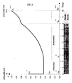
- FIG. 1 is a graph showing the evolution of the correction factor between two consecutive starts.
- FIG. 2 is a graph showing the impact of the engine stop mode on the evolution of the correction factor during the stop period.
- the life of the engine includes a discrete succession of operating and stopping periods.
- Each operating period can be broken down into a start-up phase and possibly an autorotation phase.
- T d n , T r n and T a n the respective start, autorotation (if applicable) and stop times corresponding to the nth operating period, and T d n + 1 the start time of the n + 1 th operating period.
- the quantity of fuel Q n + 1 to be injected at the instant T d n + 1 into the engine is equal to a theoretical quantity Q o calculated as a function of the speed of rotation ⁇ and the temperature of the engine T at start-up multiplied by a correction factor F c .
- the correction factor F c is then calculated by induction as follows:
- the correction factor F c applicable during the n + 1 th start, F c n + 1 is calculated from the value F c used during the n th start, F c n , modified to take into account the operation and engine stop time.
- the function F a1 is an increasing function whereas the function F a2 begins by decreasing before increasing, cf figure 2.
- the determination of the numbers of top dead centers p and q is conventionally carried out by a detector placed in front of the flywheel (method of recognizing the missing tooth, etc.) coupled to a position detector of the ignition key.
- the stop or rest time t you can use either an internal clock or timer, or use the engine temperature, for example the engine coolant water temperature T.
- the temperature of the engine at the time of its last stop is memorized and is compared with the engine temperature at the next start. We then deduce from the temperature difference ⁇ T, the stopping time from a transfer mapping.
- the correction factor is calculated by the injector computer.
- the functions f a , f d and f r are entered in the computer in the form of maps. Values F c n , q n , P n and t n are managed in specific memories.
- the functions F d and F r can be calculated from time and not from the number of top dead centers.
Landscapes
- Engineering & Computer Science (AREA)
- Chemical & Material Sciences (AREA)
- Combustion & Propulsion (AREA)
- Mechanical Engineering (AREA)
- General Engineering & Computer Science (AREA)
- Electrical Control Of Air Or Fuel Supplied To Internal-Combustion Engine (AREA)
- Control Of Vehicle Engines Or Engines For Specific Uses (AREA)
Claims (9)
- Optimierungsverfahren für die Betriebsweise eines mehrzylindrigen Motors mit Treibstoffeinspritzung für Kraftfahrzeuge, dadurch gekennzeichnet, daß es daraus besteht, während der Dauer eines Startvorgangs (n+1) eine Treibstoffmenge (Qn+1) in den Motor einzuspritzen, die gleich ist einer theoretischen Menge (Qo), die als Funktion der Drehgeschwindigkeit und der Temperatur des Motors beim Startvorgang berechnet wird, multipliziert mit einem Korrekturfaktor (FC n+1), der bestimmt wird unter Berücksichtigung- des während des vorhergehenden Startvorgangs (n) bestimmten Wertes des Korrekturfaktors (Fc n) und- der Stillstands- oder Ruhezeit (tn) zwischen dem Zeitpunkt des letzten Stillstands (Ta n) und dem Zeitpunkt des Startvorgangs (Td n+1).
- Optimierungsverfahren nach Anspruch 1, dadurch gekennzeichnet, daß der Korrekturfaktor (Fc n+1) auch von der Art und Weise abhängt, in der der letzte Motorstillstand zum Zeitpunkt (Ta n) erfolgte: Durch Betätigung des Zündschlüssels oder durch Stillstand bei eingelegtem Gang.
- Optimierungsverfahren nach einem der Ansprüche 1 bis 2, dadurch gekennzeichnet, daß der Korrekturfaktor (Fc n+1) auch von den Eigenschaften (qn, pn) der Betriebszeit des Motors abhängt, welche dem Startvorgang (n+1) vorausgeht.
- Optimierungsverfahren nach Anspruch 3, dadurch gekennzeichnet, daß die Eigenschaften der dem Startvorgang (n+1) vorausgehenden Betriebszeit des Motors festgelegt sind durch die Anzahl der oberen Totpunkte (qn), die während der Startphase registriert werden und ggf. durch die Anzahl der oberen Totpunkte (pn), die während des Selbstlaufs registriert worden sind.
- Optimierungsverfahren nach Anspruch 4, dadurch gekennzeichnet, daß der Einfluß der dem Startvorgang (n+1) vorausgehenden Betriebszeit des Motors als eine variable Funktion berechnet wird, die wie folgt definiert ist- während des Startvorgangs durch
 Fd(·): eine variable Korrekturfunktion während der Startphase istFc n: ein Korrekturfaktor ist, anwendbar während des n-ten StartvorgangsFo: eine vorgegebene Konstante istfd(·): eine Funktion ist, deren Wert zwischen 0 und 1 liegtq(·): die Anzahl der gezählten oberen Totpunkte zwischen dem Zeitpunkt des Startens Td n und dem Zeitpunkt t ist- während der Selbstlaufphase
 Fr(·): eine variable Korrekturfunktion während der Selbstlaufphase istFd(Tr n): der Wert der variablen Funktion F(·) zum Zeitpunkt des Übergangs des Startzustandes zum Selbstlaufzustand istfr(·): eine zunehmende Funktion ist, deren Wert zwischen 0 und 1 liegt undp (·): die Anzahl der gezählten oberen Totpunkte zwischen dem Zeitpunkt Tr n und dem Zeitpunkt t ist.
 - Optimierungsverfahren nach Anspruch 5, dadurch gekennzeichnet, daß der Einfluß der Art des Stillstandes berechnet wird gemäß einer kontinuierlich variablen Funktion F(t), die wie folgt definiert ist:- während eines Stillstandes durch den Zündschlüssel
 Fa1 (·): eine variable Korrekturfunktion während der Stillstandszeit ist die einem durch den Zündschlüssel bedingten Stillstand folgtFd(Ta n)= der Wert der Funktion F(t) zum Zeitpunkt Ta n des Motorstillstands istfa1(·)= eine mit der Zeit zunehmende Funktion ist, deren Wert zwischen 0 und 1 liegt- während eines Stillstands, der durch einen eingelegten Gang bewirkt wird
 Fa2 (·): eine variable Korrekturfunktion ist während der Stillstandszeit, die einem durch den eingelegten Gang bewirkten Stillstand folgtFd(Ta n): der Wert der Funktion F(t) zum Zeitpunkt Ta n des Motorstillstands istfa2(·): eine mit der Zeit zunehmende Funktion ist, deren Wert zwischen -0,5 und 1 liegt.
 - Optimierungsverfahren nach Anspruch 6, dadurch gekennzeichnet, daß der für den Startvorgang (n+1) verwendete Korrekturfaktor (Fc n+1) bestimmt wird ausgehend von der Anzahl der oberen Totpunkte (qn) der Startphase und der Anzahl der oberen Totpunkte (pn) der Selbstlaufphase, die dem Startvorgang (n+1) vorhergeht sowie vom Korrekturfaktor (Fc n), der während des Startvorgangs (n) verwendet wurde und der Stillstandszeit (tn) zwischen dem Zeitpunkt des Stillstandes (Ta n) und dem Zeitpunkt des erneuten Startvorgangs (Td n+1) gemäß der Formel- sofern der Stillstand durch den Zündschlüssel bewirkt wurde
 - sofern der Stillstand durch Selbstunterbrechung bewirkt wurde
- Optimierungsverfahren nach einem der Ansprüche 6 bis 7, dadurch gekennzeichnet, daß die Berücksichtigung der Ruhezeit begrenzt werden kann auf den Wert 1 bei Korrekturfunktionen während der Stillstandszeit (fa1, fa2), wenn diese Ruhezeiten größer sind als eine vorgegebene Zeit.
- Optimierungsverfahren nach einem der Ansprüche 1 bis 6, dadurch gekennzeichnet, daß die Messung der Ruhezeit (tn) durchgeführt wird durch Messung des Temperaturunterschiedes des Motors zwischen dem Zeitpunkt seines letzten Stillstandes (Ta n) und dem Zeitpunkt des erneuten Startvorgangs (Td n+1).
Applications Claiming Priority (2)
| Application Number | Priority Date | Filing Date | Title |
|---|---|---|---|
| FR9001843A FR2658243B1 (fr) | 1990-02-15 | 1990-02-15 | Procede d'optimisation de l'injection au redemarrage de moteurs a injection de carburant. |
| FR9001843 | 1990-02-15 |
Publications (2)
| Publication Number | Publication Date |
|---|---|
| EP0442819A1 EP0442819A1 (de) | 1991-08-21 |
| EP0442819B1 true EP0442819B1 (de) | 1993-12-08 |
Family
ID=9393769
Family Applications (1)
| Application Number | Title | Priority Date | Filing Date |
|---|---|---|---|
| EP19910400390 Expired - Lifetime EP0442819B1 (de) | 1990-02-15 | 1991-02-15 | Optimierungsverfahren der Einspritzung für das Wiederaufstarten einer mit Kraftstoff eingespritzten Brennkraftmaschine |
Country Status (4)
| Country | Link |
|---|---|
| EP (1) | EP0442819B1 (de) |
| DE (1) | DE69100729T2 (de) |
| ES (1) | ES2047382T3 (de) |
| FR (1) | FR2658243B1 (de) |
Family Cites Families (6)
| Publication number | Priority date | Publication date | Assignee | Title |
|---|---|---|---|---|
| US3628510A (en) * | 1970-06-10 | 1971-12-21 | Gen Motors Corp | Fuel supply system for an internal combustion engine providing timed cranking enrichment |
| US4148282A (en) * | 1975-03-19 | 1979-04-10 | Robert Bosch Gmbh | Method and apparatus for cold starting fuel injected internal combustion engines |
| JPS5932627A (ja) * | 1982-08-14 | 1984-02-22 | Honda Motor Co Ltd | 内燃エンジンの燃料供給方法 |
| JPS62157247A (ja) * | 1985-12-28 | 1987-07-13 | Mazda Motor Corp | エンジンの燃料制御装置 |
| JPH0665858B2 (ja) * | 1986-05-02 | 1994-08-24 | トヨタ自動車株式会社 | 内燃機関の空燃比制御方法 |
| JPH01142230A (ja) * | 1987-11-27 | 1989-06-05 | Hitachi Ltd | 内燃機関の始動時燃料増量方法 |
-
1990
- 1990-02-15 FR FR9001843A patent/FR2658243B1/fr not_active Expired - Fee Related
-
1991
- 1991-02-15 DE DE1991600729 patent/DE69100729T2/de not_active Expired - Lifetime
- 1991-02-15 ES ES91400390T patent/ES2047382T3/es not_active Expired - Lifetime
- 1991-02-15 EP EP19910400390 patent/EP0442819B1/de not_active Expired - Lifetime
Also Published As
| Publication number | Publication date |
|---|---|
| FR2658243B1 (fr) | 1994-07-29 |
| DE69100729D1 (de) | 1994-01-20 |
| DE69100729T2 (de) | 1994-05-19 |
| EP0442819A1 (de) | 1991-08-21 |
| FR2658243A1 (fr) | 1991-08-16 |
| ES2047382T3 (es) | 1994-02-16 |
Similar Documents
| Publication | Publication Date | Title |
|---|---|---|
| FR2850708A1 (fr) | Dispositif de commande d'arret et de demarrage d'un moteur a combustion interne | |
| FR2823254A1 (fr) | Appareil de commande d'emission d'un moteur a combustion interne et procede pour retarder la deterioration du catalyseur de commande d'emission | |
| FR2817809A1 (fr) | Procede et installation de mise en oeuvre d'un vehicule automobile equipe d'un moteur a combustion interne | |
| EP1696121A2 (de) | Anlassverfahren und Anlassvorrichtung für eine Brennkraftmaschine, Verfahren und Vorrichtung zur Schätzung der gebrauchten Energie während des Anlassens | |
| FR2551798A1 (fr) | Procede de commande d'alimentation en combustible d'un moteur a combustion interne immediatement apres le demarrage | |
| WO2009007605A2 (fr) | Procede de demarrage d'un moteur a combustion interne | |
| FR2575225A1 (fr) | Procede de commande en boucle fermee de la vitesse au ralenti d'un moteur a combustion interne | |
| WO2014044353A1 (fr) | Procédé d'estimation du régime d'un moteur dans une position prédéterminée | |
| WO2008059152A1 (fr) | Procede de commande d'un dispositif d'arret et de redemarrage automatique d'un moteur thermique | |
| FR2905332A1 (fr) | Procede pour demarrer un moteur a combustion interne | |
| FR2548270A1 (fr) | Procede de commande de la quantite d'air admis dans des moteurs a combustion interne a l'achevement de l'interruption de l'alimentation en carburant | |
| FR2824107A1 (fr) | Procede d'exploitation d'un moteur a combustion interne pour vehicule du type a fonctionnement intermittent | |
| FR2541728A1 (fr) | Procede de reglage du ralenti par reaction dans un moteur a combustion interne | |
| JP3859733B2 (ja) | 内燃機関の燃料噴射制御装置 | |
| EP0442819A1 (de) | Optimierungsverfahren der Einspritzung für das Wiederaufstarten einer mit Kraftstoff eingespritzten Brennkraftmaschine | |
| WO2006106254A2 (fr) | Procede et systeme de commande de decollage d'un vehicule automobile par dialogue du calculateur de controle moteur avec la boite de vitesses mecanique pilotee, pendant un redemarrage du vehicule en mode 'stop and start' | |
| WO2018109361A1 (fr) | Procédé de gestion d'une phase transitoire du démarrage d'un moteur thermique par une machine électrique | |
| WO1994024429A1 (fr) | Procede de commande d'un moteur a combustion interne lors d'une entree en regime de ralenti | |
| FR2807100A1 (fr) | Procede de montee en temperature d'un catalyseur de gaz d'echappement pour moteur a combustion interne | |
| FR2548275A1 (fr) | Procede de commande d'alimentation en combustible d'un moteur a combustion interne a plusieurs cylindres apres la fin d'une coupure de combustible | |
| FR2822899A1 (fr) | Procede permettant de determiner un volume de carburant admis au cours du processus de demarrage d'une machine a combustion interne | |
| EP0240409B1 (de) | Verfahren zur Kontrolle der Kraftstoffzufuhr zu einer Brennkraftmaschine nach Beendigung einer Kraftstoffabsperrung im Schiebebetrieb | |
| EP2761153B1 (de) | Steuerung der kraftstoffeinspritzung beim start eines verbrennungsmotors | |
| JP3777946B2 (ja) | 車両のエンジン制御装置 | |
| FR2854925A1 (fr) | Procede de demarrage d'un moteur a combustion interne notamment d'un vehicule automobile |
Legal Events
| Date | Code | Title | Description |
|---|---|---|---|
| PUAI | Public reference made under article 153(3) epc to a published international application that has entered the european phase |
Free format text: ORIGINAL CODE: 0009012 |
|
| AK | Designated contracting states |
Kind code of ref document: A1 Designated state(s): DE ES FR GB IT |
|
| 17P | Request for examination filed |
Effective date: 19920407 |
|
| 17Q | First examination report despatched |
Effective date: 19930223 |
|
| GRAA | (expected) grant |
Free format text: ORIGINAL CODE: 0009210 |
|
| AK | Designated contracting states |
Kind code of ref document: B1 Designated state(s): DE ES FR GB IT |
|
| ITF | It: translation for a ep patent filed | ||
| GBT | Gb: translation of ep patent filed (gb section 77(6)(a)/1977) |
Effective date: 19931216 |
|
| REF | Corresponds to: |
Ref document number: 69100729 Country of ref document: DE Date of ref document: 19940120 |
|
| REG | Reference to a national code |
Ref country code: ES Ref legal event code: FG2A Ref document number: 2047382 Country of ref document: ES Kind code of ref document: T3 |
|
| PLBE | No opposition filed within time limit |
Free format text: ORIGINAL CODE: 0009261 |
|
| STAA | Information on the status of an ep patent application or granted ep patent |
Free format text: STATUS: NO OPPOSITION FILED WITHIN TIME LIMIT |
|
| 26N | No opposition filed | ||
| REG | Reference to a national code |
Ref country code: GB Ref legal event code: IF02 |
|
| REG | Reference to a national code |
Ref country code: FR Ref legal event code: TP |
|
| PGFP | Annual fee paid to national office [announced via postgrant information from national office to epo] |
Ref country code: ES Payment date: 20100222 Year of fee payment: 20 |
|
| PGFP | Annual fee paid to national office [announced via postgrant information from national office to epo] |
Ref country code: FR Payment date: 20100317 Year of fee payment: 20 Ref country code: IT Payment date: 20100220 Year of fee payment: 20 |
|
| PGFP | Annual fee paid to national office [announced via postgrant information from national office to epo] |
Ref country code: GB Payment date: 20100218 Year of fee payment: 20 Ref country code: DE Payment date: 20100219 Year of fee payment: 20 |
|
| REG | Reference to a national code |
Ref country code: DE Ref legal event code: R071 Ref document number: 69100729 Country of ref document: DE |
|
| REG | Reference to a national code |
Ref country code: GB Ref legal event code: PE20 Expiry date: 20110214 |
|
| REG | Reference to a national code |
Ref country code: ES Ref legal event code: FD2A Effective date: 20110614 |
|
| PG25 | Lapsed in a contracting state [announced via postgrant information from national office to epo] |
Ref country code: GB Free format text: LAPSE BECAUSE OF EXPIRATION OF PROTECTION Effective date: 20110214 Ref country code: ES Free format text: LAPSE BECAUSE OF EXPIRATION OF PROTECTION Effective date: 20110216 |
|
| PG25 | Lapsed in a contracting state [announced via postgrant information from national office to epo] |
Ref country code: DE Free format text: LAPSE BECAUSE OF EXPIRATION OF PROTECTION Effective date: 20110215 |