EP0442739B1 - Pile à combustible d'oxyde solide - Google Patents
Pile à combustible d'oxyde solide Download PDFInfo
- Publication number
- EP0442739B1 EP0442739B1 EP91301207A EP91301207A EP0442739B1 EP 0442739 B1 EP0442739 B1 EP 0442739B1 EP 91301207 A EP91301207 A EP 91301207A EP 91301207 A EP91301207 A EP 91301207A EP 0442739 B1 EP0442739 B1 EP 0442739B1
- Authority
- EP
- European Patent Office
- Prior art keywords
- fuel cell
- solid oxide
- oxide fuel
- cell body
- sofc
- Prior art date
- Legal status (The legal status is an assumption and is not a legal conclusion. Google has not performed a legal analysis and makes no representation as to the accuracy of the status listed.)
- Expired - Lifetime
Links
Images


Classifications
-
- H—ELECTRICITY
- H01—ELECTRIC ELEMENTS
- H01M—PROCESSES OR MEANS, e.g. BATTERIES, FOR THE DIRECT CONVERSION OF CHEMICAL ENERGY INTO ELECTRICAL ENERGY
- H01M8/00—Fuel cells; Manufacture thereof
- H01M8/24—Grouping of fuel cells, e.g. stacking of fuel cells
- H01M8/241—Grouping of fuel cells, e.g. stacking of fuel cells with solid or matrix-supported electrolytes
- H01M8/2425—High-temperature cells with solid electrolytes
- H01M8/243—Grouping of unit cells of tubular or cylindrical configuration
-
- H—ELECTRICITY
- H01—ELECTRIC ELEMENTS
- H01M—PROCESSES OR MEANS, e.g. BATTERIES, FOR THE DIRECT CONVERSION OF CHEMICAL ENERGY INTO ELECTRICAL ENERGY
- H01M8/00—Fuel cells; Manufacture thereof
- H01M8/10—Fuel cells with solid electrolytes
- H01M8/12—Fuel cells with solid electrolytes operating at high temperature, e.g. with stabilised ZrO2 electrolyte
- H01M8/1231—Fuel cells with solid electrolytes operating at high temperature, e.g. with stabilised ZrO2 electrolyte with both reactants being gaseous or vaporised
-
- Y—GENERAL TAGGING OF NEW TECHNOLOGICAL DEVELOPMENTS; GENERAL TAGGING OF CROSS-SECTIONAL TECHNOLOGIES SPANNING OVER SEVERAL SECTIONS OF THE IPC; TECHNICAL SUBJECTS COVERED BY FORMER USPC CROSS-REFERENCE ART COLLECTIONS [XRACs] AND DIGESTS
- Y02—TECHNOLOGIES OR APPLICATIONS FOR MITIGATION OR ADAPTATION AGAINST CLIMATE CHANGE
- Y02E—REDUCTION OF GREENHOUSE GAS [GHG] EMISSIONS, RELATED TO ENERGY GENERATION, TRANSMISSION OR DISTRIBUTION
- Y02E60/00—Enabling technologies; Technologies with a potential or indirect contribution to GHG emissions mitigation
- Y02E60/30—Hydrogen technology
- Y02E60/50—Fuel cells
Definitions
- This invention relates to a solid oxide fuel cell.
- the fuel cell is an equipment capable of directly converting chemical energy possessed by fuel to electric energy. Since the fuel cell is free from the limitation of Carnot's cycle, it is an extremely promising technique in that the fuel cell essentially has a high energy conversion efficiency, and various fuels (naphtha, natural gas, methanol, coal reformed gas, heavy oil, etc.) may be used, and the public nuisance is less, and the power generating efficiency is not influenced by the scale of the equipment.
- the solid oxide fuel cell (hereinafter abbreviated as SOFC) operates at a high temperature of 1000°C or more, the activity of the electrode is very high, and the use of a noble metal catalyst such as expensive platinum is not completely required.
- the SOFC since the SOFC has a low polarization and a relatively high output voltage, the energy conversion efficiency is considerably higher than that in other fuel cells.
- the SOFC since the SOFC is constructed with solid materials, it is stable and has a long use life.
- Fig. 6 sectionally shows an example of this type of the SOFC.
- numeral 10 is a supply tube for introducing an oxidizing gas such as air or the like, numeral 6 a bottomed cylindrical porous support tube, numeral 7 an air electrode, numeral 8 a solid electrolyte, numeral 9 a fuel electrode, numeral 16 an upper plate supporting the oxidizing gas supply tube 10 and dividing an oxidizing gas chamber 27 and an exhausts gas chamber 17, numeral 20 a bottom plate supporting an SOFC body 5 and provided with a fuel hole 20a communicating a cell reaction chamber 19 to a fuel chamber 26, numeral 18 a plate holding an outer periphery of an opening side of the SOFC body 5 and provided with a gas hole 18a communicating the cell reaction chamber 19 to the exhaust gas chamber 17.
- an oxidizing gas such as air or the like
- numeral 6 a bottomed cylindrical porous support tube
- numeral 7 an air electrode
- numeral 8 a solid electrolyte
- numeral 16 an upper plate supporting the oxidizing gas supply tube 10 and dividing an oxidizing
- the oxidizing gas such as air or the like
- the oxidizing gas supply tube 10 As shown by an arrow A, it is discharged from an outlet port 10a for the oxidizing gas and turned at the bottomed portion inside the SOFC body 5 as shown by an arrow B to flow out into the exhaust gas chamber 17 as shown by an arrow C.
- a fuel gas such as H 2 , CH 4 or the like is flown through the fuel hole 20a of the bottom plate 20 along an outer surface of the SOFC body 5 as shown by an arrow D.
- oxygen inside the SOFC body 5 flows as an oxygen ion through the solid electrolyte 8 to the fuel electrode 9 and reacts with the fuel gas at the fuel electrode 9 to generate a current between the air electrode 7 and the fuel electrode 9, whereby the cell can be used as a fuel cell.
- the fuel cell is used at a high temperature of about 1000°C, the shape of Fig. 6 capable of constructing without a seal portion is said to be preferable because the occurrence of thermal stress can be reduced.
- the oxidizing gas supply tube 10 and the SOFC body 5 are separately made and the holding of the supply tube 10 is attained only by engaging with the upper plate 16, so that there is caused a problem that the positioning of the supply tube 10 in the SOFC body 5 becomes difficult.
- the position of the supply tube 10 to the SOFC body 5 changes due to the difficulty of the positioning, when the oxidizing gas such as air or the like is supplied through the supply tube 10 and turned at the bottomed portion inside the SOFC body 5 to rise upward between the outer surface of the supply tube 10 and the inner surface of the SOFC body 5, the flowing of the oxidizing gas changes in accordance with the position of the supply tube 10 in the SOFC body 5, so that there is a problem of varying performance between cells.
- the oxidizing gas such as air or the like
- EP-A-0242201 describes a fuel cell generator in which a conduit extends into each fuel cell. Conduits are described as having external fins to provide a self-centering action.
- EP-A-0376579 published after the declared priority date of the present application, discloses a ceramic double tube comprising an outer tube with one end closed, a concentric inner tube, and at least one support member extending laterally to bridge the outer and inner tubes.
- a ceramic double tube comprising an outer tube with one end closed, a concentric inner tube, and at least one support member extending laterally to bridge the outer and inner tubes.
- One mentioned use of such a tube is in a fuel cell.
- an object of the invention to provide a solid oxide fuel cell which can accurately determine the positioning of the supply tube for oxidizing gas or fuel gas inside the SOFC body and has sufficient mechanical strength and fixing strength against vibrations or the like in the mounting or during use.
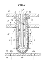
- Fig. 1 is sectionally shown a first embodiment of SOFC according to the invention
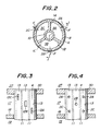
- Fig. 2 is a sectional view taken along a line II-II of Fig. 1.
- Fig. 1 corresponds to a section taken along a line I-I of Fig. 2.
- Fig. 6 the same function part as in Fig. 6 is represented by the same numeral.
- a bottomed cylindrical porous support tube 6 and a solid electrolyte 8 in an SOFC body 15 are extended upward in the drawing and an outer peripheral surface 30 of the SOFC body 15 at its opening end side is rigidly held by and fixed to an upper plate 16.
- three flat plate partition members 1A, 1B, 1C are radially arranged from the the outer peripheral surface of the oxidizing gas supply tube 10 toward the inner peripheral surface of the SOFC body 15 as shown in Fig. 2, whereby the hollow space is divided into three oxidizing gas flowing passages 3A, 3B, 3C.
- a ring-like sealing member 4 is arranged between the gas supply tube 10 and the bottomed cylindrical porous support tube 6 to prevent the discharging of the oxidizing gas from the gas flowing passages 3A, 3B, 3C to an oxidising gas chamber 27.
- the oxidizing gas flowing passages 3A, 3B, 3C are arranged exhaust ports 2A, 2B, 2C for the oxidizing gas facing to the exhaust gas chamber 17, respectively.
- the height levels of these exhaust ports 2A, 2B, 2C are made different in up and down directions in such a manner that two or more adjacent exhaust ports are not existent on the same cut plane when the SOFC body 15 is horizontally cut in the lateral direction.
- the oxidizing gas is supplied from a supply port 10a of the oxidizing gas supply tube 10 to the hollow space of the SOFC body 15 and discharged from the gas flowing passages 3A, 3B, 3C through the exhaust ports 2A, 2B, 2C to the inside of the exhaust gas chamber 17 as shown by an arrow F.
- the air electrode 7 may be made from doped or undoped LaMnO 3 , CaMnO 3 , LaNiO 3 , LaCoO 3 , LaCrO 3 or the like, among which LaMnO 3 doped with strontium is preferable.
- the solid electrolyte 8 may generally be made from zirconia stabilized with yttria or the like.
- the fuel electrode 9 is generally made from nickel-zirconia cermet or cobalt-zirconia cermet.
- the heights of the exhaust ports 2A, 2B, 2C for the oxidizing gas are rendered into different levels so as not to adjacently exist these exhaust ports at the same level, so that the bending strength does not locally lower.
- Figs. 3 and 4 are partial sectional views of another embodiments illustrating the portion of the SOFC near to the opening end side, respectively.
- each of rectangular slit-like exhaust ports 12A, 12B, 12C for the oxidizing gas is arranged in each of the respective oxidizing gas flowing passages 13 (the same exhaust ports are arranged at a side not shown).
- the SOFC of Fig. 4 is a modified embodiment of the SOFC shown in Fig. 3, in which the oxidizing gas flowing passage 13 provided with two exhaust ports 2A, 2C and the oxidizing gas flowing passage 13 provided with an exhaust port 2B are alternately arranged in the circumferential direction of the SOFC body so as to position the height of the exhaust port 2B between the heights of the exhaust ports 2A and 2C.
- Fig. 5 shows the other embodiment of the SOFC according to the invention, which is a modified embodiment of Fig. 1.
- a disc-like depression 29a is formed in an upper plate 29, and the upper part of the SOFC body 15 is inserted into the depression 29a, whereby the outer peripheral surface 30 of the SOFC body 15 is held by and fixed to the upper plate 29.
- the exhaust ports 2A, 2B, 2C for the oxidizing gas are arranged in the respective oxidizing gas flowing passages 3A, 3B, 3C to conduct the discharge of the oxidizing gas having a reduced concentration likewise Fig. 1.
- the leakage of the oxidizing gas passing upward in each of the oxidizing gas flowing passages 3A, 3B, 3C is prevented by the closing member 4.
- the fuel electrode 9 is arranged outside the air electrode 7, but such an electrode arrangement may be reversed.
- the fuel gas is supplied to the hollow space of the SOFC body, while the oxidizing gas is supplied to the outside of the SOFC body.
- the number of flat plate partition members dividing the hollow space or the number of the gas flowing passages may be varied.
- the number of the flat plate partition members may be about 12. Even when the number of the flat plate partition members increases, the loss of the hollow space can be reduced by thinning the thickness of each of the partition members.
- the partition member dividing the hollow space may take various shapes such as wavy form in section and the like in addition to the flat plate.
- unit cell is formed on the bottomed cylindrical porous body, but the cell body may be made self-dependent by constructing the air electrode with a rigid body.
- the partition member is fastened between the inner peripheral surface of the solid oxide fuel cell body and the outer peripheral surface of the gas supply tube, so that the gas supply tube can surely be positioned in the hollow space of the fuel cell body, whereby the scattering of power generation performances in the SOFC body due to the relative position change between the gas supply tube and the SOFC body can be eliminated and the mechanical strengths of the SOFC body can considerably be increased.
- the outer peripheral surface of the SOFC body at its opening end side is fixed to the upper plate, so that the SOFC body itself can rigidly be held and hence the gas supply tube is held by and fixed to the SOFC body through the partition members.
- the opening end of the SOFC body is sealed by the closing member and at least one exhaust port is arranged in each of the gas flowing passages for discharging a gas having a reduced concentration to the exhaust gas chamber, so that the gas having the reduced concentration is not retained in all of the gas flowing passages and a fresh gas is always passed through the hollow space, and consequently the full areas of the air electrode and the fuel electrode can effectively be utilized for power generation to improve the power generation efficiency.
Landscapes
- Life Sciences & Earth Sciences (AREA)
- Engineering & Computer Science (AREA)
- Manufacturing & Machinery (AREA)
- Sustainable Development (AREA)
- Sustainable Energy (AREA)
- Chemical & Material Sciences (AREA)
- Chemical Kinetics & Catalysis (AREA)
- Electrochemistry (AREA)
- General Chemical & Material Sciences (AREA)
- Fuel Cell (AREA)
Claims (7)
- Pile à combustible d'oxyde solide comprenant :un corps (15) de pile à combustible d'oxyde solide cylindrique à fond, au moins pourvu d'un électrolyte solide (8), d'une électrode à air (7) et d'une électrode à combustible (9);un tube (10) d'alimentation en gaz pour fournir un gaz oxydant ou un gaz combustible à un espace creux du corps (15) de la pile à combustible d'oxyde solide;des organes de séparation (1) s'étendant entre une surface périphérique interne du corps (15) de la pile à combustible d'oxyde solide et une surface périphérique externe du tube (10) d'alimentation en gaz et divisant l'espace creux du corps (15) de la pile à combustible d'oxyde solide en un certain nombre de passages d'écoulement de gaz (3) s'étendant le long du corps (15) de la pile à combustible d'oxyde solide;un organe d'étanchéité (4) s'étendant entre la surface périphérique interne du corps (15) de la pile à combustible d'oxyde solide et la surface périphérique externe du tube (10) d'alimentation en gaz afin de fermer l'extrémité d'ouverture du corps de la pile à combustible d'oxyde solide;un moyen de support (16) maintenant une surface périphérique externe (30) du corps (15) de la pile à combustible d'oxyde solide, qui se trouve à l'extrémité d'ouverture du corps (15) de la pile à combustible d'oxyde solide; etau moins un orifice d'échappement (2) formé à travers le corps (15) de la pile à combustible d'oxyde solide à partir de chacun des passages d'écoulement de gaz (3) pour évacuer le gaz oxydant ou le gaz combustible s'écoulant dans le passage d'écoulement de gaz à partir de ces passages, dans une chambre (17) de gaz d'échappement placée autour dudit corps (15) de la pile à combustible d'oxyde solide, à proximité dudit moyen de support (16).
- Pile à combustible d'oxyde solide selon la revendication 1 où lesdits orifices d'échappement (2) formés dans lesdits passages d'écoulement de gaz (3) ont des niveaux différents en hauteur relativement à l'orifice d'échappement (2) des autres passages d'écoulement de gaz (3) afin de ne pas se trouver au même plan de coupe quand ledit corps (15) de la pile à combustible est horizontalement coupé en direction latérale.
- Pile à combustible d'oxyde solide selon la revendication 1 où ladite électrode à air est faite de LaMnO3, CaMnO3, LaNiO3, LaCoO3 ou LaCrO3 dopés ou non dopés.
- Pile à combustible d'oxyde solide selon la revendication 3, où ladite électrode à air (7) est faite de LaMnO3 dopé du strontium.
- Pile à combustible d'oxyde solide selon la revendication 1 où ledit électrolyte solide (8) est fait de zircone stabilisée à l'oxyde d'yttrium.
- Pile à combustible d'oxyde solide selon la revendication 1 où ladite électrode à combustible (9) est faite d'un cermet de nickel-zircone ou d'un cermet de cobalt-zircone.
- Pile à combustible d'oxyde solide selon l'une quelconque des revendications précédentes où une longueur du corps (15) de la pile à combustible d'oxyde solide n'a pas d'électrode, ladite longueur qui n'a pas d'électrode comprenant la région du contact entre le moyen de support (16) et ladite surface périphérique externe (30) à l'extrémité d'ouverture du corps de la pile à combustible d'oxyde solide (15) et comprenant de plus la portion du corps de la pile à combustible solide (15) où sont formés lesdits orifices d'échappement (2).
Applications Claiming Priority (2)
| Application Number | Priority Date | Filing Date | Title |
|---|---|---|---|
| JP2032384A JP2528988B2 (ja) | 1990-02-15 | 1990-02-15 | 固体電解質型燃料電池 |
| JP32384/90 | 1990-02-15 |
Publications (2)
| Publication Number | Publication Date |
|---|---|
| EP0442739A1 EP0442739A1 (fr) | 1991-08-21 |
| EP0442739B1 true EP0442739B1 (fr) | 1997-05-02 |
Family
ID=12357464
Family Applications (1)
| Application Number | Title | Priority Date | Filing Date |
|---|---|---|---|
| EP91301207A Expired - Lifetime EP0442739B1 (fr) | 1990-02-15 | 1991-02-14 | Pile à combustible d'oxyde solide |
Country Status (5)
| Country | Link |
|---|---|
| US (1) | US5176967A (fr) |
| EP (1) | EP0442739B1 (fr) |
| JP (1) | JP2528988B2 (fr) |
| CA (1) | CA2036260C (fr) |
| DE (1) | DE69125872T2 (fr) |
Families Citing this family (13)
| Publication number | Priority date | Publication date | Assignee | Title |
|---|---|---|---|---|
| US5514486A (en) * | 1995-09-01 | 1996-05-07 | The Regents Of The University Of California, Office Of Technology Transfer | Annular feed air breathing fuel cell stack |
| US5595834A (en) * | 1995-09-01 | 1997-01-21 | The Regents Of The University Of Calif. | Annular feed air breathing fuel cell stack |
| USRE39556E1 (en) * | 1997-11-20 | 2007-04-10 | Relion, Inc. | Fuel cell and method for controlling same |
| US6030718A (en) | 1997-11-20 | 2000-02-29 | Avista Corporation | Proton exchange membrane fuel cell power system |
| US6096449A (en) * | 1997-11-20 | 2000-08-01 | Avista Labs | Fuel cell and method for controlling same |
| US5993985A (en) * | 1998-04-09 | 1999-11-30 | Siemens Westinghouse Power Corporation | Fuel cell tubes and method of making same |
| US6468682B1 (en) | 2000-05-17 | 2002-10-22 | Avista Laboratories, Inc. | Ion exchange membrane fuel cell |
| US7326480B2 (en) * | 2000-05-17 | 2008-02-05 | Relion, Inc. | Fuel cell power system and method of controlling a fuel cell power system |
| US20020003085A1 (en) * | 2000-05-19 | 2002-01-10 | Chandran Ravi R. | Multilayer electrochemical cell technology using sol-gel processing applied to ceramic oxygen generator |
| US6376117B1 (en) * | 2000-07-18 | 2002-04-23 | Sofco L.P. | Internal fuel staging for improved fuel cell performance |
| DE10136710A1 (de) * | 2001-07-27 | 2003-02-13 | Siemens Ag | Hochtemperatur-Brennstoffzellen-Reaktor mit HPD-Zellen |
| DE102015210139A1 (de) * | 2015-06-02 | 2016-12-08 | Robert Bosch Gmbh | Brennstoffzellenvorrichtung |
| CN114824351B (zh) * | 2020-03-24 | 2024-01-26 | 苏州国绿新材料科技有限公司 | 固体型氧化物燃料电池单元 |
Family Cites Families (9)
| Publication number | Priority date | Publication date | Assignee | Title |
|---|---|---|---|---|
| US3460991A (en) * | 1967-08-16 | 1969-08-12 | Gen Electric | Fuel cell with tubular electrodes and solid electrolyte |
| ZA814990B (en) * | 1980-12-22 | 1982-11-24 | Westinghouse Electric Corp | Fuel cell generator |
| ZA817158B (en) * | 1980-12-22 | 1983-01-26 | Westinghouse Electric Corp | High temperature solid electrolyte fuel cell configurations and interconnections |
| US4374184A (en) * | 1981-09-29 | 1983-02-15 | Westinghouse Electric Corp. | Fuel cell generator and method of operating same |
| US4664986A (en) * | 1986-04-16 | 1987-05-12 | Westinghouse Electric Corp. | High thermal conductivity gas feeder system |
| JPS63207054A (ja) * | 1987-02-23 | 1988-08-26 | Fujikura Ltd | 固体電解質燃料電池発電装置 |
| US4751152A (en) * | 1987-04-06 | 1988-06-14 | Westinghouse Electric Corp. | High bulk self-supporting electrode with integral gas feed conduit for solid oxide fuel cells |
| US4827606A (en) * | 1988-05-11 | 1989-05-09 | The United States Of America As Represented By The United States Department Of Energy | Method and apparatus for assembling solid oxide fuel cells |
| DE68908140T2 (de) * | 1988-12-22 | 1994-02-03 | Ngk Insulators Ltd | Keramikrohr mit einseitig geschlossenem Rohrmantel und Verfahren zu dessen Herstellung. |
-
1990
- 1990-02-15 JP JP2032384A patent/JP2528988B2/ja not_active Expired - Lifetime
-
1991
- 1991-02-07 US US07/651,972 patent/US5176967A/en not_active Expired - Fee Related
- 1991-02-13 CA CA002036260A patent/CA2036260C/fr not_active Expired - Fee Related
- 1991-02-14 DE DE69125872T patent/DE69125872T2/de not_active Expired - Fee Related
- 1991-02-14 EP EP91301207A patent/EP0442739B1/fr not_active Expired - Lifetime
Also Published As
| Publication number | Publication date |
|---|---|
| JP2528988B2 (ja) | 1996-08-28 |
| CA2036260C (fr) | 1997-07-01 |
| CA2036260A1 (fr) | 1991-08-16 |
| DE69125872T2 (de) | 1997-09-18 |
| JPH03238759A (ja) | 1991-10-24 |
| EP0442739A1 (fr) | 1991-08-21 |
| DE69125872D1 (de) | 1997-06-05 |
| US5176967A (en) | 1993-01-05 |
Similar Documents
| Publication | Publication Date | Title |
|---|---|---|
| US5185219A (en) | Solid oxide fuel cells | |
| US6348280B1 (en) | Fuel cell | |
| EP0505186B1 (fr) | Pile à combustible à électrolyte solide | |
| EP0055016B1 (fr) | Arrangements de piles à combustible à électrolyte solide fonctionnant à haute température | |
| EP0442739B1 (fr) | Pile à combustible d'oxyde solide | |
| EP1969660B1 (fr) | Pile à combustible et empilage de piles à combustible | |
| EP0536925B1 (fr) | Unités de cellule pour piles à combustible à oxydes solides et générateur d'énergie utilisant ces unités de cellule | |
| EP1625635B1 (fr) | Pile a combustible | |
| US7125619B2 (en) | Fuel cell and fuel cell stack | |
| JPH0362460A (ja) | 固体電解質型燃料電池 | |
| US20040053108A1 (en) | Fuel cell | |
| JP4897273B2 (ja) | 燃料電池 | |
| JPH0737595A (ja) | 固体電解質型燃料電池 | |
| JP4300947B2 (ja) | 固体酸化物形燃料電池 | |
| US7258944B2 (en) | Fuel cell with improved separators and circular disk-shaped electrolyte electrode assemblies | |
| JPH03238760A (ja) | 固体電解質型燃料電池 | |
| JPH0758618B2 (ja) | 固体電解質型燃料電池 | |
| JP2698481B2 (ja) | 発電装置 | |
| JP2967878B2 (ja) | 固体電解質型燃料電池のガス供給構造 | |
| JPH06196196A (ja) | 固体電解質型燃料電池 | |
| JPH11233127A (ja) | 円盤積層固体電解質型燃料電池 | |
| JPH034456A (ja) | 固体電解質燃料電池 | |
| JPH06203868A (ja) | 固体電解質型燃料電池式発電炉 | |
| JP2010192376A (ja) | 燃料電池 |
Legal Events
| Date | Code | Title | Description |
|---|---|---|---|
| PUAI | Public reference made under article 153(3) epc to a published international application that has entered the european phase |
Free format text: ORIGINAL CODE: 0009012 |
|
| AK | Designated contracting states |
Kind code of ref document: A1 Designated state(s): BE DE FR GB |
|
| 17P | Request for examination filed |
Effective date: 19920211 |
|
| 17Q | First examination report despatched |
Effective date: 19931207 |
|
| GRAG | Despatch of communication of intention to grant |
Free format text: ORIGINAL CODE: EPIDOS AGRA |
|
| GRAH | Despatch of communication of intention to grant a patent |
Free format text: ORIGINAL CODE: EPIDOS IGRA |
|
| GRAH | Despatch of communication of intention to grant a patent |
Free format text: ORIGINAL CODE: EPIDOS IGRA |
|
| GRAA | (expected) grant |
Free format text: ORIGINAL CODE: 0009210 |
|
| AK | Designated contracting states |
Kind code of ref document: B1 Designated state(s): BE DE FR GB |
|
| REF | Corresponds to: |
Ref document number: 69125872 Country of ref document: DE Date of ref document: 19970605 |
|
| ET | Fr: translation filed | ||
| PGFP | Annual fee paid to national office [announced via postgrant information from national office to epo] |
Ref country code: GB Payment date: 19980204 Year of fee payment: 8 |
|
| PGFP | Annual fee paid to national office [announced via postgrant information from national office to epo] |
Ref country code: FR Payment date: 19980213 Year of fee payment: 8 |
|
| PGFP | Annual fee paid to national office [announced via postgrant information from national office to epo] |
Ref country code: DE Payment date: 19980217 Year of fee payment: 8 |
|
| PGFP | Annual fee paid to national office [announced via postgrant information from national office to epo] |
Ref country code: BE Payment date: 19980218 Year of fee payment: 8 |
|
| PLBE | No opposition filed within time limit |
Free format text: ORIGINAL CODE: 0009261 |
|
| STAA | Information on the status of an ep patent application or granted ep patent |
Free format text: STATUS: NO OPPOSITION FILED WITHIN TIME LIMIT |
|
| 26N | No opposition filed | ||
| PG25 | Lapsed in a contracting state [announced via postgrant information from national office to epo] |
Ref country code: GB Free format text: LAPSE BECAUSE OF NON-PAYMENT OF DUE FEES Effective date: 19990214 |
|
| PG25 | Lapsed in a contracting state [announced via postgrant information from national office to epo] |
Ref country code: BE Free format text: LAPSE BECAUSE OF NON-PAYMENT OF DUE FEES Effective date: 19990228 |
|
| BERE | Be: lapsed |
Owner name: NGK INSULATORS LTD Effective date: 19990228 |
|
| GBPC | Gb: european patent ceased through non-payment of renewal fee |
Effective date: 19990214 |
|
| PG25 | Lapsed in a contracting state [announced via postgrant information from national office to epo] |
Ref country code: FR Free format text: LAPSE BECAUSE OF NON-PAYMENT OF DUE FEES Effective date: 19991029 |
|
| PG25 | Lapsed in a contracting state [announced via postgrant information from national office to epo] |
Ref country code: DE Free format text: LAPSE BECAUSE OF NON-PAYMENT OF DUE FEES Effective date: 19991201 |
|
| REG | Reference to a national code |
Ref country code: FR Ref legal event code: ST |