EP0442499B1 - Flüssigkristallzusammensetzung, Flüssigkristallvorrichtung, Anzeigevorrichtung und diese verwendende Anzeigemethode - Google Patents
Flüssigkristallzusammensetzung, Flüssigkristallvorrichtung, Anzeigevorrichtung und diese verwendende Anzeigemethode Download PDFInfo
- Publication number
- EP0442499B1 EP0442499B1 EP91102104A EP91102104A EP0442499B1 EP 0442499 B1 EP0442499 B1 EP 0442499B1 EP 91102104 A EP91102104 A EP 91102104A EP 91102104 A EP91102104 A EP 91102104A EP 0442499 B1 EP0442499 B1 EP 0442499B1
- Authority
- EP
- European Patent Office
- Prior art keywords
- liquid crystal
- denotes
- crystal composition
- carbon atoms
- display method
- Prior art date
- Legal status (The legal status is an assumption and is not a legal conclusion. Google has not performed a legal analysis and makes no representation as to the accuracy of the status listed.)
- Expired - Lifetime
Links
- 239000004973 liquid crystal related substance Substances 0.000 title claims abstract description 186
- 239000000203 mixture Substances 0.000 title claims abstract description 93
- 238000000034 method Methods 0.000 title claims description 31
- 125000004432 carbon atom Chemical group C* 0.000 claims abstract description 42
- 150000001875 compounds Chemical group 0.000 claims abstract description 32
- 125000000217 alkyl group Chemical group 0.000 claims abstract description 28
- 229910052739 hydrogen Inorganic materials 0.000 claims abstract description 21
- 239000001257 hydrogen Substances 0.000 claims abstract description 21
- 125000002023 trifluoromethyl group Chemical group FC(F)(F)* 0.000 claims abstract description 18
- PXGOKWXKJXAPGV-UHFFFAOYSA-N Fluorine Chemical compound FF PXGOKWXKJXAPGV-UHFFFAOYSA-N 0.000 claims abstract description 12
- 229910052731 fluorine Inorganic materials 0.000 claims abstract description 12
- 239000011737 fluorine Substances 0.000 claims abstract description 12
- 125000001424 substituent group Chemical group 0.000 claims abstract description 9
- 125000003545 alkoxy group Chemical group 0.000 claims abstract description 5
- 239000003607 modifier Substances 0.000 claims description 54
- 239000004990 Smectic liquid crystal Substances 0.000 claims description 8
- OKTJSMMVPCPJKN-UHFFFAOYSA-N Carbon Chemical compound [C] OKTJSMMVPCPJKN-UHFFFAOYSA-N 0.000 claims description 7
- UFHFLCQGNIYNRP-UHFFFAOYSA-N Hydrogen Chemical compound [H][H] UFHFLCQGNIYNRP-UHFFFAOYSA-N 0.000 claims description 3
- 230000003098 cholesteric effect Effects 0.000 claims description 3
- 150000002431 hydrogen Chemical class 0.000 claims 9
- 230000000694 effects Effects 0.000 claims 3
- 229910052799 carbon Inorganic materials 0.000 claims 1
- 230000002441 reversible effect Effects 0.000 abstract description 19
- 125000004435 hydrogen atom Chemical class [H]* 0.000 abstract description 9
- 230000004807 localization Effects 0.000 abstract description 6
- 239000010410 layer Substances 0.000 description 39
- 210000004027 cell Anatomy 0.000 description 28
- 210000002858 crystal cell Anatomy 0.000 description 27
- 239000005262 ferroelectric liquid crystals (FLCs) Substances 0.000 description 23
- 230000004044 response Effects 0.000 description 21
- OKKJLVBELUTLKV-UHFFFAOYSA-N Methanol Chemical compound OC OKKJLVBELUTLKV-UHFFFAOYSA-N 0.000 description 18
- 238000005259 measurement Methods 0.000 description 17
- RTZKZFJDLAIYFH-UHFFFAOYSA-N Diethyl ether Chemical compound CCOCC RTZKZFJDLAIYFH-UHFFFAOYSA-N 0.000 description 16
- 238000006243 chemical reaction Methods 0.000 description 16
- XLYOFNOQVPJJNP-UHFFFAOYSA-N water Substances O XLYOFNOQVPJJNP-UHFFFAOYSA-N 0.000 description 16
- YXFVVABEGXRONW-UHFFFAOYSA-N Toluene Chemical compound CC1=CC=CC=C1 YXFVVABEGXRONW-UHFFFAOYSA-N 0.000 description 15
- 230000010287 polarization Effects 0.000 description 15
- ZMXDDKWLCZADIW-UHFFFAOYSA-N N,N-Dimethylformamide Chemical compound CN(C)C=O ZMXDDKWLCZADIW-UHFFFAOYSA-N 0.000 description 13
- XEKOWRVHYACXOJ-UHFFFAOYSA-N Ethyl acetate Chemical compound CCOC(C)=O XEKOWRVHYACXOJ-UHFFFAOYSA-N 0.000 description 12
- 230000002269 spontaneous effect Effects 0.000 description 12
- JRMUNVKIHCOMHV-UHFFFAOYSA-M tetrabutylammonium bromide Chemical compound [Br-].CCCC[N+](CCCC)(CCCC)CCCC JRMUNVKIHCOMHV-UHFFFAOYSA-M 0.000 description 12
- 239000013078 crystal Substances 0.000 description 11
- 230000005684 electric field Effects 0.000 description 11
- 0 *Oc(c(C#N)c1C#N)ccc1O Chemical compound *Oc(c(C#N)c1C#N)ccc1O 0.000 description 10
- 206010047571 Visual impairment Diseases 0.000 description 10
- 230000003247 decreasing effect Effects 0.000 description 10
- 239000002904 solvent Substances 0.000 description 10
- 239000012043 crude product Substances 0.000 description 9
- 238000001035 drying Methods 0.000 description 9
- VEXZGXHMUGYJMC-UHFFFAOYSA-N hydrochloric acid Substances Cl VEXZGXHMUGYJMC-UHFFFAOYSA-N 0.000 description 9
- 150000002500 ions Chemical class 0.000 description 9
- 239000011541 reaction mixture Substances 0.000 description 8
- 239000000243 solution Substances 0.000 description 8
- 239000004988 Nematic liquid crystal Substances 0.000 description 7
- 125000004093 cyano group Chemical group *C#N 0.000 description 7
- 238000001914 filtration Methods 0.000 description 7
- 238000003756 stirring Methods 0.000 description 7
- QTBSBXVTEAMEQO-UHFFFAOYSA-N Acetic acid Chemical compound CC(O)=O QTBSBXVTEAMEQO-UHFFFAOYSA-N 0.000 description 6
- 239000007864 aqueous solution Substances 0.000 description 6
- 239000012044 organic layer Substances 0.000 description 6
- CSNNHWWHGAXBCP-UHFFFAOYSA-L Magnesium sulfate Chemical compound [Mg+2].[O-][S+2]([O-])([O-])[O-] CSNNHWWHGAXBCP-UHFFFAOYSA-L 0.000 description 5
- 230000015572 biosynthetic process Effects 0.000 description 5
- 238000003786 synthesis reaction Methods 0.000 description 5
- LFQSCWFLJHTTHZ-UHFFFAOYSA-N Ethanol Chemical compound CCO LFQSCWFLJHTTHZ-UHFFFAOYSA-N 0.000 description 4
- 230000002238 attenuated effect Effects 0.000 description 4
- 230000008859 change Effects 0.000 description 4
- 238000010586 diagram Methods 0.000 description 4
- 239000003480 eluent Substances 0.000 description 4
- 238000000605 extraction Methods 0.000 description 4
- 238000010438 heat treatment Methods 0.000 description 4
- KWYUFKZDYYNOTN-UHFFFAOYSA-M potassium hydroxide Inorganic materials [OH-].[K+] KWYUFKZDYYNOTN-UHFFFAOYSA-M 0.000 description 4
- 238000001556 precipitation Methods 0.000 description 4
- 238000010898 silica gel chromatography Methods 0.000 description 4
- HEMHJVSKTPXQMS-UHFFFAOYSA-M sodium hydroxide Inorganic materials [OH-].[Na+] HEMHJVSKTPXQMS-UHFFFAOYSA-M 0.000 description 4
- 239000000758 substrate Substances 0.000 description 4
- MPAIWVOBMLSHQA-UHFFFAOYSA-N 3,6-dihydroxybenzene-1,2-dicarbonitrile Chemical compound OC1=CC=C(O)C(C#N)=C1C#N MPAIWVOBMLSHQA-UHFFFAOYSA-N 0.000 description 3
- UHOVQNZJYSORNB-UHFFFAOYSA-N Benzene Chemical compound C1=CC=CC=C1 UHOVQNZJYSORNB-UHFFFAOYSA-N 0.000 description 3
- YMWUJEATGCHHMB-UHFFFAOYSA-N Dichloromethane Chemical compound ClCCl YMWUJEATGCHHMB-UHFFFAOYSA-N 0.000 description 3
- 238000004891 communication Methods 0.000 description 3
- 230000007423 decrease Effects 0.000 description 3
- 230000005621 ferroelectricity Effects 0.000 description 3
- 239000011521 glass Substances 0.000 description 3
- 238000004519 manufacturing process Methods 0.000 description 3
- 239000000463 material Substances 0.000 description 3
- 238000002156 mixing Methods 0.000 description 3
- 238000012545 processing Methods 0.000 description 3
- 238000010992 reflux Methods 0.000 description 3
- RAOQLAYIDNKQHG-UHFFFAOYSA-N (4-pentylcyclohexyl)methanol Chemical compound CCCCCC1CCC(CO)CC1 RAOQLAYIDNKQHG-UHFFFAOYSA-N 0.000 description 2
- NYFMNLNTXFMPGL-UHFFFAOYSA-N (4-pentylcyclohexyl)methyl methanesulfonate Chemical compound CCCCCC1CCC(COS(C)(=O)=O)CC1 NYFMNLNTXFMPGL-UHFFFAOYSA-N 0.000 description 2
- MXBCYQUALCBQIJ-RYVPXURESA-N (8s,9s,10r,13s,14s,17r)-13-ethyl-17-ethynyl-11-methylidene-1,2,3,6,7,8,9,10,12,14,15,16-dodecahydrocyclopenta[a]phenanthren-17-ol;(8r,9s,13s,14s,17r)-17-ethynyl-13-methyl-7,8,9,11,12,14,15,16-octahydro-6h-cyclopenta[a]phenanthrene-3,17-diol Chemical compound OC1=CC=C2[C@H]3CC[C@](C)([C@](CC4)(O)C#C)[C@@H]4[C@@H]3CCC2=C1.C1CC[C@@H]2[C@H]3C(=C)C[C@](CC)([C@](CC4)(O)C#C)[C@@H]4[C@@H]3CCC2=C1 MXBCYQUALCBQIJ-RYVPXURESA-N 0.000 description 2
- OHBQPCCCRFSCAX-UHFFFAOYSA-N 1,4-Dimethoxybenzene Chemical compound COC1=CC=C(OC)C=C1 OHBQPCCCRFSCAX-UHFFFAOYSA-N 0.000 description 2
- CHCLRVOURKGRSW-UHFFFAOYSA-N 1,4-dibromo-2,5-dimethoxybenzene Chemical compound COC1=CC(Br)=C(OC)C=C1Br CHCLRVOURKGRSW-UHFFFAOYSA-N 0.000 description 2
- MNDIARAMWBIKFW-UHFFFAOYSA-N 1-bromohexane Chemical compound CCCCCCBr MNDIARAMWBIKFW-UHFFFAOYSA-N 0.000 description 2
- XCVWVIHAUUKVAL-UHFFFAOYSA-N 2,5-dihydroxybenzene-1,4-dicarbonitrile Chemical compound OC1=CC(C#N)=C(O)C=C1C#N XCVWVIHAUUKVAL-UHFFFAOYSA-N 0.000 description 2
- PKLOSECFAMYVCD-UHFFFAOYSA-N 2,5-dimethoxybenzene-1,4-dicarbonitrile Chemical compound COC1=CC(C#N)=C(OC)C=C1C#N PKLOSECFAMYVCD-UHFFFAOYSA-N 0.000 description 2
- RPSXPPXHTTXUTE-UHFFFAOYSA-N 2-hexoxy-5-hydroxybenzene-1,4-dicarbonitrile Chemical compound CCCCCCOC1=CC(C#N)=C(O)C=C1C#N RPSXPPXHTTXUTE-UHFFFAOYSA-N 0.000 description 2
- GTQZUSKKYDNKNK-UHFFFAOYSA-N 3-hexoxy-6-hydroxybenzene-1,2-dicarbonitrile Chemical compound CCCCCCOC1=CC=C(O)C(C#N)=C1C#N GTQZUSKKYDNKNK-UHFFFAOYSA-N 0.000 description 2
- OFGDYNUBVQKYOH-UHFFFAOYSA-N 3-hydroxy-6-[(4-pentylcyclohexyl)methoxy]benzene-1,2-dicarbonitrile Chemical compound C1CC(CCCCC)CCC1COC1=CC=C(O)C(C#N)=C1C#N OFGDYNUBVQKYOH-UHFFFAOYSA-N 0.000 description 2
- JUJWROOIHBZHMG-UHFFFAOYSA-N Pyridine Chemical compound C1=CC=NC=C1 JUJWROOIHBZHMG-UHFFFAOYSA-N 0.000 description 2
- WYURNTSHIVDZCO-UHFFFAOYSA-N Tetrahydrofuran Chemical compound C1CCOC1 WYURNTSHIVDZCO-UHFFFAOYSA-N 0.000 description 2
- KBPLFHHGFOOTCA-UHFFFAOYSA-N caprylic alcohol Natural products CCCCCCCCO KBPLFHHGFOOTCA-UHFFFAOYSA-N 0.000 description 2
- 230000000052 comparative effect Effects 0.000 description 2
- 238000013500 data storage Methods 0.000 description 2
- 230000006870 function Effects 0.000 description 2
- 239000004615 ingredient Substances 0.000 description 2
- 239000007788 liquid Substances 0.000 description 2
- VLKZOEOYAKHREP-UHFFFAOYSA-N n-Hexane Chemical compound CCCCCC VLKZOEOYAKHREP-UHFFFAOYSA-N 0.000 description 2
- FBUKVWPVBMHYJY-UHFFFAOYSA-N nonanoic acid Chemical compound CCCCCCCCC(O)=O FBUKVWPVBMHYJY-UHFFFAOYSA-N 0.000 description 2
- 229920001721 polyimide Polymers 0.000 description 2
- BWHMMNNQKKPAPP-UHFFFAOYSA-L potassium carbonate Chemical compound [K+].[K+].[O-]C([O-])=O BWHMMNNQKKPAPP-UHFFFAOYSA-L 0.000 description 2
- 239000000047 product Substances 0.000 description 2
- 238000001953 recrystallisation Methods 0.000 description 2
- 238000012546 transfer Methods 0.000 description 2
- 238000002834 transmittance Methods 0.000 description 2
- 238000005406 washing Methods 0.000 description 2
- JASMXDWQDAVBDJ-UHFFFAOYSA-N (2,3,5,6-tetrafluoro-4-hydroxyphenyl) nonanoate Chemical compound CCCCCCCCC(=O)OC1=C(F)C(F)=C(O)C(F)=C1F JASMXDWQDAVBDJ-UHFFFAOYSA-N 0.000 description 1
- WSLDOOZREJYCGB-UHFFFAOYSA-N 1,2-Dichloroethane Chemical compound ClCCCl WSLDOOZREJYCGB-UHFFFAOYSA-N 0.000 description 1
- ZSDAMBJDFDRLSS-UHFFFAOYSA-N 2,3,5,6-tetrafluorobenzene-1,4-diol Chemical compound OC1=C(F)C(F)=C(O)C(F)=C1F ZSDAMBJDFDRLSS-UHFFFAOYSA-N 0.000 description 1
- NSTREUWFTAOOKS-UHFFFAOYSA-N 2-fluorobenzoic acid Chemical compound OC(=O)C1=CC=CC=C1F NSTREUWFTAOOKS-UHFFFAOYSA-N 0.000 description 1
- PPWKQEDYUMJFNK-UHFFFAOYSA-N 4-pentylcyclohexane-1-carbonyl chloride Chemical compound CCCCCC1CCC(C(Cl)=O)CC1 PPWKQEDYUMJFNK-UHFFFAOYSA-N 0.000 description 1
- RGUKYNXWOWSRET-UHFFFAOYSA-N 4-pyrrolidin-1-ylpyridine Chemical compound C1CCCN1C1=CC=NC=C1 RGUKYNXWOWSRET-UHFFFAOYSA-N 0.000 description 1
- BVKZGUZCCUSVTD-UHFFFAOYSA-M Bicarbonate Chemical compound OC([O-])=O BVKZGUZCCUSVTD-UHFFFAOYSA-M 0.000 description 1
- 229920002799 BoPET Polymers 0.000 description 1
- WKBOTKDWSSQWDR-UHFFFAOYSA-N Bromine atom Chemical compound [Br] WKBOTKDWSSQWDR-UHFFFAOYSA-N 0.000 description 1
- QOSSAOTZNIDXMA-UHFFFAOYSA-N Dicylcohexylcarbodiimide Chemical compound C1CCCCC1N=C=NC1CCCCC1 QOSSAOTZNIDXMA-UHFFFAOYSA-N 0.000 description 1
- 239000012359 Methanesulfonyl chloride Substances 0.000 description 1
- 239000005041 Mylar™ Substances 0.000 description 1
- 239000004642 Polyimide Substances 0.000 description 1
- 230000005856 abnormality Effects 0.000 description 1
- 239000002253 acid Substances 0.000 description 1
- PQLAYKMGZDUDLQ-UHFFFAOYSA-K aluminium bromide Chemical compound Br[Al](Br)Br PQLAYKMGZDUDLQ-UHFFFAOYSA-K 0.000 description 1
- -1 aluminum lithium hydride Chemical compound 0.000 description 1
- 239000011324 bead Substances 0.000 description 1
- GDTBXPJZTBHREO-UHFFFAOYSA-N bromine Substances BrBr GDTBXPJZTBHREO-UHFFFAOYSA-N 0.000 description 1
- 229910052794 bromium Inorganic materials 0.000 description 1
- 239000000872 buffer Substances 0.000 description 1
- 239000003990 capacitor Substances 0.000 description 1
- 230000003197 catalytic effect Effects 0.000 description 1
- 239000003795 chemical substances by application Substances 0.000 description 1
- 230000009918 complex formation Effects 0.000 description 1
- 238000001816 cooling Methods 0.000 description 1
- DOBRDRYODQBAMW-UHFFFAOYSA-N copper(i) cyanide Chemical compound [Cu+].N#[C-] DOBRDRYODQBAMW-UHFFFAOYSA-N 0.000 description 1
- 238000011161 development Methods 0.000 description 1
- 239000006185 dispersion Substances 0.000 description 1
- 230000005592 electrolytic dissociation Effects 0.000 description 1
- 238000011156 evaluation Methods 0.000 description 1
- 229940044631 ferric chloride hexahydrate Drugs 0.000 description 1
- 238000011049 filling Methods 0.000 description 1
- 239000000706 filtrate Substances 0.000 description 1
- 125000000524 functional group Chemical group 0.000 description 1
- 238000007429 general method Methods 0.000 description 1
- 239000012535 impurity Substances 0.000 description 1
- AMGQUBHHOARCQH-UHFFFAOYSA-N indium;oxotin Chemical compound [In].[Sn]=O AMGQUBHHOARCQH-UHFFFAOYSA-N 0.000 description 1
- 230000003993 interaction Effects 0.000 description 1
- NQXWGWZJXJUMQB-UHFFFAOYSA-K iron trichloride hexahydrate Chemical compound O.O.O.O.O.O.[Cl-].Cl[Fe+]Cl NQXWGWZJXJUMQB-UHFFFAOYSA-K 0.000 description 1
- 238000007726 management method Methods 0.000 description 1
- QARBMVPHQWIHKH-UHFFFAOYSA-N methanesulfonyl chloride Chemical compound CS(Cl)(=O)=O QARBMVPHQWIHKH-UHFFFAOYSA-N 0.000 description 1
- 238000013508 migration Methods 0.000 description 1
- 230000005012 migration Effects 0.000 description 1
- TVMXDCGIABBOFY-UHFFFAOYSA-N n-Octanol Natural products CCCCCCCC TVMXDCGIABBOFY-UHFFFAOYSA-N 0.000 description 1
- 230000007935 neutral effect Effects 0.000 description 1
- IAFGQCSBAQSHFW-UHFFFAOYSA-N octyl 3-fluoro-4-hydroxybenzoate Chemical compound CCCCCCCCOC(=O)C1=CC=C(O)C(F)=C1 IAFGQCSBAQSHFW-UHFFFAOYSA-N 0.000 description 1
- 230000003287 optical effect Effects 0.000 description 1
- 229910000027 potassium carbonate Inorganic materials 0.000 description 1
- 230000008569 process Effects 0.000 description 1
- UMJSCPRVCHMLSP-UHFFFAOYSA-N pyridine Natural products COC1=CC=CN=C1 UMJSCPRVCHMLSP-UHFFFAOYSA-N 0.000 description 1
- 150000003242 quaternary ammonium salts Chemical class 0.000 description 1
- 230000000717 retained effect Effects 0.000 description 1
- 150000003839 salts Chemical class 0.000 description 1
- 229910052708 sodium Inorganic materials 0.000 description 1
- 239000011734 sodium Substances 0.000 description 1
- 229910000030 sodium bicarbonate Inorganic materials 0.000 description 1
- UIIMBOGNXHQVGW-UHFFFAOYSA-M sodium bicarbonate Substances [Na+].OC([O-])=O UIIMBOGNXHQVGW-UHFFFAOYSA-M 0.000 description 1
- 125000006850 spacer group Chemical group 0.000 description 1
- 238000004544 sputter deposition Methods 0.000 description 1
- QAOWNCQODCNURD-UHFFFAOYSA-N sulfuric acid Substances OS(O)(=O)=O QAOWNCQODCNURD-UHFFFAOYSA-N 0.000 description 1
- PBCFLUZVCVVTBY-UHFFFAOYSA-N tantalum pentoxide Inorganic materials O=[Ta](=O)O[Ta](=O)=O PBCFLUZVCVVTBY-UHFFFAOYSA-N 0.000 description 1
- YLQBMQCUIZJEEH-UHFFFAOYSA-N tetrahydrofuran Natural products C=1C=COC=1 YLQBMQCUIZJEEH-UHFFFAOYSA-N 0.000 description 1
- 230000007704 transition Effects 0.000 description 1
Images


Classifications
-
- C—CHEMISTRY; METALLURGY
- C09—DYES; PAINTS; POLISHES; NATURAL RESINS; ADHESIVES; COMPOSITIONS NOT OTHERWISE PROVIDED FOR; APPLICATIONS OF MATERIALS NOT OTHERWISE PROVIDED FOR
- C09K—MATERIALS FOR MISCELLANEOUS APPLICATIONS, NOT PROVIDED FOR ELSEWHERE
- C09K19/00—Liquid crystal materials
- C09K19/52—Liquid crystal materials characterised by components which are not liquid crystals, e.g. additives with special physical aspect: solvents, solid particles
- C09K19/58—Dopants or charge transfer agents
- C09K19/582—Electrically active dopants, e.g. charge transfer agents
Definitions
- the present invention relates to a liquid crystal composition, a liquid crystal device, a display apparatus and a display method, and particularly to a liquid crystal composition containing a specific resistivity modifier improving display characteristics, a liquid crystal device using the composition, a display apparatus using the device, and a display method using the composition, device and apparatus.
- liquid crystal devices comprising nematic liquid crystals
- DS dynamic scattering
- TN twisted nematic
- the DS mode liquid crystal device required lowering the resistivity of its liquid crystal layer because there occur difficulties such that incident light is not scattered and that a threshold voltage for driving the device is increased if the resistivity of the liquid crystal layer remains at a high level.
- liquid crystal materials used for the DS mode liquid crystal device generally comprise liquid crystal having a negative dielectric anisotropy (- ⁇ ) (hereinafter, referred to as "N-type liquid crystal” and containing no functional groups such as a cyano group showing a large electron attractive characteristic in liquid crystal molecules in many cases.
- N-type liquid crystal liquid crystal having a negative dielectric anisotropy (- ⁇ )
- N-type liquid crystal no functional groups such as a cyano group showing a large electron attractive characteristic in liquid crystal molecules in many cases.
- the resistivity can be lowered easily by only adding a small amount of quaternary ammonium salts such as tetrabutylammonium bromide ([CH3(CH2)3]4N+ ⁇ Br ⁇ , abbreviated as TBAB).
- TBAB tetrabutylammonium bromide
- TN mode liquid crystal device liquid crystal materials having high resistivities have generally been used.
- a DC (direct current) voltage can be applied to the device because of abnormality in a power supply switch in some cases.
- the DC voltage does not disappear easily, so that a non-display state can continue for several tens of seconds.
- the duration of the non-display state can be shortened by lowering the resistivity of the liquid crystal layer in the TN mode liquid crystal device.
- a small amount of TBAB as described above can be added to the TN mode liquid crystal.
- TBAB has poor electrochemical stability in a long time, whereby the resistivity once lowered is gradually increased to a high level, thus leading to disadvantages, such as a change in threshold characteristic of the liquid crystal.
- a ferroelectric liquid crystal device comprising a liquid crystal showing a chiral smectic phase and ferroelectricity has a peculiar problem as described hereinbelow.
- JP-A 63-135922 Japanese Laid-Open Patent Application No. (JP-A) 63-135922.
- JP-A 63-135922 it is described that the ion localization is caused by migration of ionic impurities in a liquid crystal layer in response to an electric field caused by polarization of liquid crystal molecules.
- an electrically stable state is provided by forming a counter electric field due to the ion localization in reverse to the electric field given by the polarization of the liquid crystal molecule.
- JP-A 64-78235 proposes a solution by controlling the values of spontaneous polarization Ps, capacitance Ci of the insulating layer, resistivity Ri of the insulating layer and capacitance C LC of the liquid crystal layer.
- An object of the present invention is to provide a liquid crystal composition containing a resistivity modifier (compound) which can stably lower a resistivity (R LC ) of a liquid crystal layer with good reproducibility and durability.
- Another object of the present invention is to provide a liquid crystal composition containing a resistivity modifier having good solubility in the composition in view of difficulty such that a salt such as tetrabutylammonium bromide (TBAB) generally has poor solubility in a liquid crystal to precipitate its crystal particularly at low temperatures.
- a salt such as tetrabutylammonium bromide (TBAB) generally has poor solubility in a liquid crystal to precipitate its crystal particularly at low temperatures.
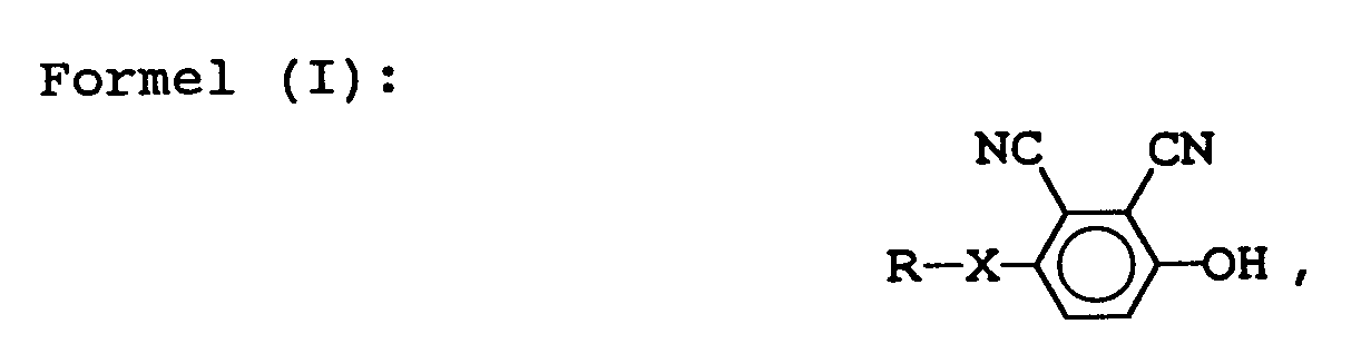
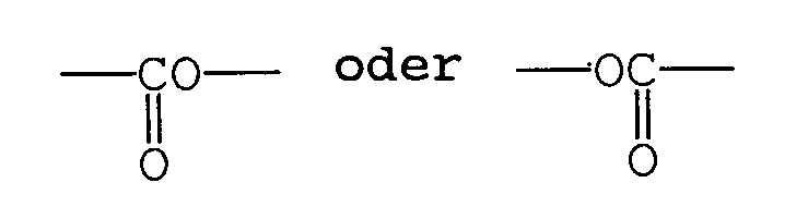
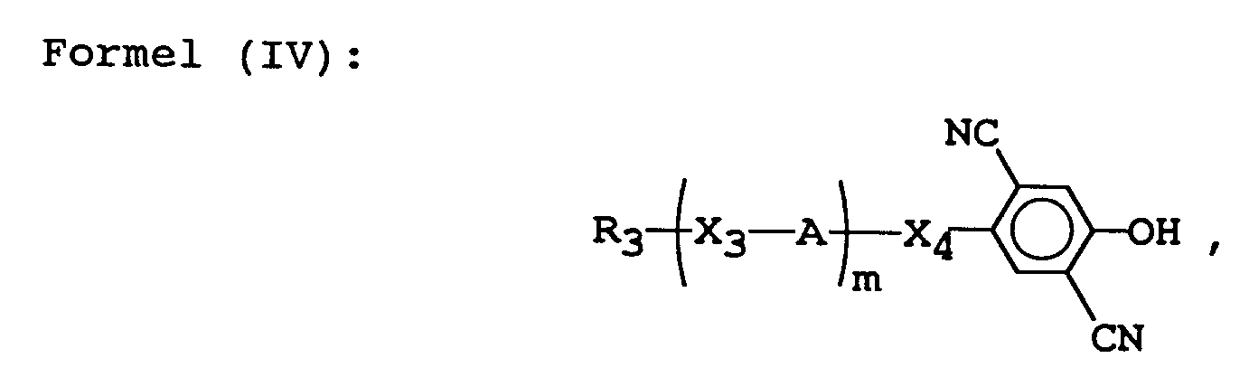
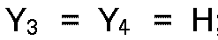
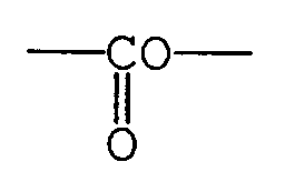
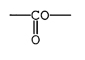
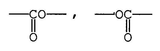
- a liquid crystal composition containing at least one resistivity modifier compound represented by the following formulas (I) to (IV): wherein R denotes hydrogen, or a linear or branched alkyl group having 1 - 18 carbon atoms; and X denotes -O-, wherein R1 denotes a linear or branched alkyl or alkocy group having 1 - 18 carbon atoms; and X1 denotes or -CH2O-: wherein R2 denotes hydrogen, or a linear or branched alkyl group having 1 - 18 carbon atoms; X2 denotes a single bond, -O-, Y1, Y2, Y3 and Y4 respectively denote hydrogen, fluorine or -CF3 with proviso that at least one of Y1, Y2, Y3 and Y4 is fluorine or -CF3; and n is 0 or 1, with the proviso that Y1 to Y4 are not
- the present invention provides a liquid crystal device comprising a pair of electrode plates and the liquid crystal composition described above disposed between the electrode plates.
- the present invention further provides a display apparatus comprising the liquid crystal device.
- the present invention still further provides a display method using the liquid crystal composition, the liquid crystal device or the display apparatus.
- the present invention has been accomplished as a further development of JP-A 63-135922 and minimizes a drawback to a display described below due to the above-mentioned reverse voltage caused by a spontaneous polarization.
- the spontaneous polarization when the spontaneous polarization is large, switching can not effectively be conducted by means of an external electric field and the device does not satisfy fundamental characteristics.
- the spontaneous polarization When the spontaneous polarization is small, bistability can be obtained but the reverse voltage functions like a DC bias to deteriorate image quality in the display.
- the reverse voltage in an FLC display is related with fundamental characteristics of a display panel and an image quality such as afterimage to affect display characteristics.
- R may include the following groups (i) and (ii):
- X may preferably be -O- in the formula (I).
- resistivity modifier represented by the above-mentioned general formula (I) may include those denoted by the following structural formulas.
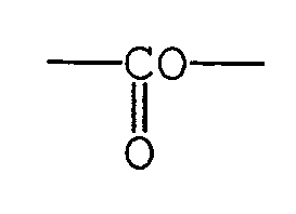
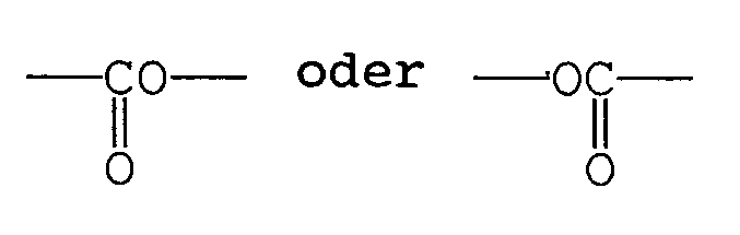
- the resistivity modifier represented by the formula (I) may generally be synthesized through the following reaction schemes. (Case where X is -O-) In the above, Y denotes -Br, -I or and R denotes the same as defined above. (Case where X is In the above, R denotes the same as defined above.
- the crystal was extracted with ether, and the ether layer was washed with 5 %-sodium hydrogen-carbonate aqueous solution and further washed with water, followed by distilling-off of the solvent to obtain a crude product.
- the crude product was treated with activated carbon and recrystalized from methanol to obtain 13.1 g of 2,3-dicyano-4-hexyloxyphenol.
- R1 may preferably be an n-alkyl group having 1 - 18 carbon atoms, more preferably 3 - 14 carbon atoms.
- resistivity modifier represented by the formula (II) may include those denoted by the following structural formulas.
- the resistivity modifier represented by the formula (II) may generally be synthesized through the following reaction schemes. (Case where X1 is (Case where X1 is -CH2O)
- Example Compound No. 2-20 4-n-pentylcyclohexylmethyl 2,3-dicyano-4-hydroxyphenyl ether (Example Compound No. 2-20) was synthesized through the following steps i) - iii).
- the organic layer was washed successively with 5 %-sodium hydrogenecarbonate aqueous solution and water, followed by drying with anhydrous magnesium sulfate and distilling-off of the solvent to obtain a crude product.
- the crude product was purified by silica gel column chromatography (eluent: toluene/ethyl acetate) and treated with activated carbon, followed by recrystallization from methanol to obtain 3.6 g of 4-n-pentylcyclohexylmethyl 2,3-dicyano-4-hydroxyphenyl ether.
- R2 may preferably be any one of hydrogen and the following groups (i) and (ii):
- Y1, Y2, Y3 and Y4 may preferably include the following combinations (iii) to (xi):
- resistivity modifier represented by the formula (III) may include those denoted by the following structural formulas.
- the resistivity modifier represented by the formula (III) may generally be synthesized through the following reaction schemes. (Case where X2 is -O-) (Case where X2 is (Case where X2 is (Case where X2 is
- R3 may preferably include any of the following groups (i) and (ii):
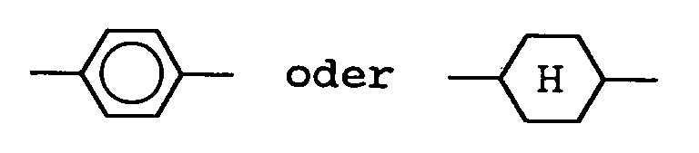
- X4 may preferably be -O- or when m is 0 and may preferably be when m is 1.
- X3 may preferably be a single bond when -A- is
- resistivity modifier represented by the formula (IV) may include those denoted by the following structural formulas.
- the resistivity modifier represented by the formula (IV) may generally be synthesized through the following reaction schemes. (Case where X4 is -O-)
- Example Compound No. 4-3 4-hexyloxy-2,5-dicyanophenol (Example Compound No. 4-3) was synthesized through the following steps i) to iv).
- the crystal was recovered by filtration and washed successively with 20 %-ammonia water, water, and methanol, followed by drying to obtain 142 g of 2,5-dicyano-1,4-dimethoxybenzene (Yield: 74.8 %).
- the crude product was dissolved in ethanol and treated with activated carbon, followed by recrystallization from ethanol to obtain 8.2 g of 4-hexyloxy-2,5-dicyanophenol (Yield: 22.9 %).
- At least one resistivity modifier represented by the formulas (I) - (IV) may preferably be contained at 0.01 - 5 wt. %, more preferably 0.05 - 2 wt. %, further preferably 0.2 - 1 wt. % in the composition.
- the two or more species of resistivity modifiers of the formulas (I) to (IV) may preferably be contained at 0.01 - 10 wt. %, more preferably 0.01 - 4 wt. %, further preferably 0.2 - 2 wt. % in the composition.
- the above-mentioned two or more species of resistivity modifiers may be selected from those represented by at least one of the formulas (I) to (IV).
- two or more species of resistivity modifiers it is possible to increase the addition amount thereof to the composition without precipitation.
- 3 wt. % of one resistivity modifier used in the present invention is added to the composition, there can occur precipitation of the resistivity modifier due to poor solubility at a lower temperature in particular though a resistivity of a liquid crystal layer is sufficiently lowered.
- the addition amount of each resistivity modifier can be 1.5 wt. %. As a result, no precipitation occurs even at a lower temperature and a low resistivity state can be retained stably.
- the liquid crystal composition according to the present invention containing at least one resistivity modifier represented by the formulas (I) to (IV) may assume a mesomorphic phase such as a nematic phase, a cholesteric phase, a smectic phase or a chiral smectic phase.
- the liquid crystal device according to the present invention may preferably be prepared by heating the liquid crystal composition prepared as described above into an isotropic liquid under vacuum, filling a blank cell comprising a pair of oppositely spaced electrode plates with the composition, gradually cooling the cell to form a liquid crystal layer and restoring the normal pressure.
- Figure 1 is a schematic sectional view of an embodiment of the liquid crystal device utilizing ferroelectricity prepared as described above for explanation of the structure thereof.
- the liquid crystal device includes a liquid crystal layer 18 assuming a chiral smectic phase disposed between a pair of glass substrates 11 each having thereon a transparent electrode 12 comprising a film of, e.g., ITO (indium-tin-oxide) and an insulating and alignment control layer 13.
- the liquid crystal layer 18 comprises a position ion 14 and a negative ion 15.
- liquid crystal molecules show two stable states 16 and 17.
- a liquid crystal display apparatus of the present invention which uses the liquid crystal device according to the present invention as a display panel portion.
- the ferroelectric liquid crystal display apparatus 101 includes a graphic controller 102, a display panel 103, a scanning line drive circuit 104, a data line drive circuit 105, a decoder 106, a scanning signal generator 107, a shift resistor 108, a line memory 109, a data signal generator 110, a drive control circuit 111, a graphic central processing unit (GCPU) 112, a host central processing unit (host CPU) 113, and an image data storage memory (VRAM) 114.
- the liquid crystal device further comprises a pair of cross nicol polarizing plates.
- Image data are generated in the graphic controller 102 in an apparatus body and transferred to a display panel 103 by signal transfer means shown in Figures 5 and 6.
- the graphic controller 102 principally comprises a CPU (central processing unit, hereinafter referred to as "GCPU") 112 and a VRAM (video-RAM, image data storage memory) 114 and is in charge of management and communication of image data between a host CPU 113 and the liquid crystal display apparatus (FLCD) 101.
- the control of the display apparatus is principally realized in the graphic controller 102.
- a light source is disposed at the back of the display panel 103.
- a ferroelectric liquid crystal device (cell) having a 1.5 micron-thick liquid crystal layer as shown in Figure 1 was prepared in the following manner.
- each transparent electrode (ITO) 12 disposed on a pair of glass substrates 11 a 1000 ⁇ -thick insulating layer 13 comprising Ta2O5 was formed by sputtering. Further, a 100 ⁇ -thick alignment control layer 13 comprising polyimide (e.g., SE-100, mfd. by Nissan Kagaku K.K.) was formed on the insulating layer 13. The thus prepared pair of glass substrates were placed opposite to each other to prepare a blank cell.
- polyimide e.g., SE-100, mfd. by Nissan Kagaku K.K.
- Liquid crystal compositions having different spontaneous polarizations Ps were respectively prepared by mixing the following ingredients in prescribed proportions.
- a resistivity modifier (Example Compound No. 1-10) represented by the formula (I) was added to each liquid crystal composition prepared above in an amount of 1 wt. %, and then each of the resultant liquid crystal compositions was injected into the blank cell to prepare the ferroelectric liquid crystal device (cell).
- a control cell was prepared separately by omitting the insulating layer.
- a saturation voltage pulse sufficient to cause a 100 % inversion for the control cell was applied to each sample cell and the areal proportion of the inverted proportion was measured in terms of a ratio of the transmittance through the sample cell to that through the control cell.
- Table 1 Inverted Proportion (%) (at 25 o C) Ps (nC/cm2) Resistivity Modifier (1 wt.%) Added Not added 30 about 60 ⁇ 40 25 90 about 60 20 100 80 15 100 90 10 100 100 100
- Ferroelectric liquid crystal cells were prepared in the same manner as in Example 1 except that a resistivity modifier and the addition amount thereof were changed as shown in Table 2 appearing hereinafter.
- the resistivity of a liquid crystal layer (R LC ) for measurement is measured by a method shown in Figure 3A.
- a rectangular wave is applied from a function generator to a cell 31 for resistivity measurement to which a Mylar capacitor 32 (capacitance: Ci) is externally applied.
- the cell 31 comprises an alignment layer comprising a thin polyimide film (thickness: ⁇ 50 ⁇ ) disposed on an ITO electrode.
- a voltage waveform of the cell 31 measured through a buffer amplifier 34 is given, e.g., as shown in Figure 3B.
- a maximum voltage V0 is attempted to V0/e (e: the base of natural logarithm) in a time ⁇ (sec) counted from the polarity inversion of a rectangular wave.
- Figure 4A shows a change in luminance (transmittance) based on a photomultiplier output signal level of "white” when a pulse voltage for switching into “white” is applied to a cell which is currently showing “black” under right-angle cross-nicol polarizers. In several seconds, the level of luminance is lower than the saturation level. We refer to this phenomenon as “shortage or retardation of response”. A time from the pulse voltage application until the luminance reaches the prescribed "white” level is referred to as “response retardation time”.
- the above-mentioned response retardation may be attributable to a phenomenon that the reverse voltage causes liquid crystal molecules to return to "black” when a pulse for switching from "black” to “white” is applied, thus lowering the luminance of "white” level during the presence of the reverse voltage.
- the volume resistivity of the liquid crystal layer was stably and repetitively lowered by adding the resistivity modifier used in the present invention. Further, as shown in Figure 4, the response retardation substantially or completely disappeared to remarkably decrease panel afterimages (image (e.g., "black”) remaining on subsequently displayed images (e.g., "white”) in a display panel).
- image e.g., "black
- subsequently displayed images e.g., "white
- Ferroelectric liquid crystal cells were prepared in the same manner as in Example 1 except that the resistivity modifier of Ex. Comp. Nos. (1-1), (1-3), (1-6), (1-16), (1-24), (1-25), (1-28) and (1-32) were used.
- the above prepared liquid crystal compositions or cells were respectively subjected to measurement of a volume resistivity ( ⁇ LC ) and a response retardation time in the same manner as in Examples 2 - 7 to obtain good display characteristics with decreased panel afterimages.
- Ferroelectric liquid crystal cells were prepared in the same manner as in Example 1 except for using the resistivity modifier of Ex. Comp. No. (2-4) instead of (1-10) and respectively subjected to measurement of an inverted proportion. The results are shown in Table 3 below. Table 3 Inverted Proportion (%) (at 25 o C) Ps (nC/cm2) Resistivity Modifier (1 wt.%) Added Not added 30 about 60 ⁇ 40 25 90 about 60 20 100 80 15 100 90 10 100 100 100
- Ferroelectric liquid crystal cells were prepared in the same manner as in addition amounts shown in Table 4 below were used.
- the above prepared liquid crystal cells were respectively subjected to measurement of a volume resistivity ( ⁇ LC ) and a response retardation time in the same manner as in Examples 2 - 7.
- the results are shown in Table 4 below.
- liquid crystal composition of the present invention containing the resistivity modifier had a lower volume resistivity to shorten the response retardation time, whereby panel after images were decreased.
- Liquid crystal cells were prepared in the same manner as in Example 1 by using commercial available liquid crystals shown in Table 5 below.
- the liquid crystal cells were respectively subjected to measurement of a volume resistivity ( ⁇ LC ) and a response retardation time in the same manner as in Examples 2 - 7. The results are shown in Table 5 below.
- the resistivity modifier used in the present invention could lower the volume resistivity and the response retardation time of each of such different liquid crystals.
- Ferroelectric liquid crystal cells were prepared in the same manner as in Example 10 except that the resistivity modifiers of Ex. Comp. Nos. (2-2), (2-8), (2-9), (2-11), (2-15), (2-23) and (2-27) were used instead of (2-20), and respectively subjected to measurement of a volume resistivity ( ⁇ LC ) and a response retardation time in the same manner as in Examples 2 - 7 to obtain good display characteristics with decreased panel after images similar to those in Example 10.
- the resistivity modifiers of Ex. Comp. Nos. (2-2), (2-8), (2-9), (2-11), (2-15), (2-23) and (2-27) were used instead of (2-20), and respectively subjected to measurement of a volume resistivity ( ⁇ LC ) and a response retardation time in the same manner as in Examples 2 - 7 to obtain good display characteristics with decreased panel after images similar to those in Example 10.
- Ferroelectric liquid crystal cells were prepared in the same manner as in Example 1 except for using the resistivity modifier of Ex. Comp. No. (3-28) instead of (1-10) and respectively subjected to measurement of a reverse proportion. The results are shown in Table 6 below. Further, volume resistivities of the above-prepared liquid crystal cells showed the following values.
- Ferroelectric liquid crystal cells were prepared in the same manner as in addition amounts shown in Table 7 below were used.
- the above prepared liquid crystal cells were respectively subjected to measurement of a volume resistivity ( ⁇ LC ) and a response retardation time in the same manner as in Examples 2 - 7.
- the results are shown in Table 7 below. From the above results, the liquid crystal composition of the present invention containing the resistivity modifier had a lower volume resistivity to shorten the response retardation time, whereby panel after images were decreased.
- Ferroelectric liquid crystal cells were prepared in the same manner as in Example 18 except that the resistivity modifiers of Ex. Comp. Nos. (3-1), (3-5), (3-11), (3-15), (3-42), (3-61) and (3-67) were used instead of (3-28), and respectively subjected to measurement of a volume resistivity ( ⁇ LC ) and a response retardation time in the same manner as in Examples 2 - 7 to obtain good display characteristics with decreased panel after images similar to those in Example 18.
- Ferroelectric liquid crystal cells were prepared in the same manner as in addition amounts shown in Table 8 below were used.
- the above prepared liquid crystal cells were respectively subjected to measurement of a volume resistivity ( ⁇ LC ) and a response retardation time in the same manner as in Examples 2 - 7.
- the results are shown in Table 8 below.
- the liquid crystal of the present invention containing the resistivity modifier had a lower volume resistivity to shorten the response retardation time, whereby panel after images were decreased.
- Liquid crystal cells were prepared by mixing a commercially available ferroelectric liquid crystal (CS-1014, mfd. by Chisso K.K.) with the materials shown below in prescribed proportions, and respectively subjected to measurement of a volume resistivity ( ⁇ LC ) in the same manner as in Examples 2 - 7. The results are shown in Figure 7.
- CS-1014 ferroelectric liquid crystal
- ⁇ LC volume resistivity
- N-type nematic liquid crystal composition containing no cyano group was prepared by using mesomorphic compounds represented by the following formulas in indicated proportions to show a clearing point of 72 o C.
- the liquid crystal cells were prepared by mixing the above nematic liquid crystal composition with the following compounds (resistivity modifiers) in indicated proportions, and respectively subjected to measurement of a volume resistivity ( ⁇ LC ) in the same manner as in Examples 2 - 7. The results are shown in Table 9 below.
- a blank cell was prepared by using two electrode plates each provided with an ITO film coated thereon with a homeotropic aligning agent (ODS-E, mfd. by Chisso K.K.) and applying the two electrode plates to each other.
- ODS-E homeotropic aligning agent
- the cell gap was 10 microns and the thickness of the alignment layer was 50 ⁇ (after drying).
- Example 29 Into the blank cell, the liquid crystal composition prepared in Example 29 was injected to prepare a liquid crystal device.
- Liquid crystal cell were prepared in the same manner as in Examples 29 - 33 except that a p-type nematic liquid crystal having a cyano group (ZLI-2411, mfd. by E. Merck) was used instead of the nematic liquid crystal composition having no cyano group and that TBAB was used in Comparative Example.
- a p-type nematic liquid crystal having a cyano group ZLI-2411, mfd. by E. Merck
- the resistivity modifiers (a) to (d) used in the present invention could effectively lower the resistivities of the above liquid crystals whether the liquid crystals had a cyano group or not.
- blank liquid crystal cells were respectively prepared by using a pair of electrode substrates each having a transparent electrode coated with an alignment film (thickness ⁇ 50 ⁇ (after drying)) for examining stability of a nematic liquid crystal composition.
- Liquid crystal compositions respectively containing the resistivity modifiers (a) to (d) used in Examples 34 - 38 and TBAB used in Comparative Example in respectively indicated addition amounts in Table 10 were respectively injected into the above-prepared blank cell to prepare liquid crystal cells.
- the liquid crystal cells were subjected to DC voltage application (20 V) and then subjected to measurement of volume resistivities before and after the DC voltage application.
- the liquid crystal cells containing the resistivity modifiers used in Examples 34 - 38 respectively showed substantially no change in the volume resistivity even after 30 hours compared with those in Table 10.
- the liquid crystal cell containing TBAB showed increase in the volume resistivity by 20 % after 30 hours compared with that in Table 10.
- the resistivity modifier used in the present invention provided a liquid crystal composition having good stability of the volume resistivity even after a long lapse of time.
- the liquid crystal composition containing at least one resistivity modifier of the formulas (I) - (IV) according to the present invention can have a stably and durably decreased resistivity of the liquid crystal layer. Since the resistivity modifier is added in a small amount, the resistivity modifier has little or no influence on characteristics such as a viscosity and a phase transition temperature of the liquid crystal composition.
- the liquid crystal device comprising the liquid crystal composition, and the display method using the composition and the device according to the present invention can provide remarkably improved image qualities such that: bistability of liquid crystal molecules is improved in a liquid crystal cell having an insulating layer; and switching of a display image is smoothly conducted since afterimages of "blurring black” caused by a reverse voltage are attenuated quickly due to a low resistivity when a "black” data signal is changed into a “white” data signal.
- a display apparatus utilizing the liquid crystal device of the present invention as a display unit, which shows good display characteristic in combination with a light source, a drive circuit, etc.
Landscapes
- Chemical & Material Sciences (AREA)
- Crystallography & Structural Chemistry (AREA)
- Engineering & Computer Science (AREA)
- Materials Engineering (AREA)
- Organic Chemistry (AREA)
- Liquid Crystal Substances (AREA)
- Liquid Crystal (AREA)
Claims (48)
- Flüssigkristallmischung, die mindestens eine Verbindung enthält, die durch die folgenden Formeln (I) bis (IV) wiedergegeben wird:


- Flüssigkristallmischung nach Anspruch 1, bei der R in der Formel (I) durch irgendeine der folgenden Gruppen (i) und (ii) wiedergegeben wird:(i) eine n-Alkylgruppe mit 1 bis 18 Kohlenstoffatomen und(ii)

- Flüssigkristallmischung nach Anspruch 1, bei der X -O- bezeichnet.
- Flüssigkristallmischung nach Anspruch 1, bei der R₁ eine n-Alkylgruppe mit 1 bis 18 Kohlenstoffatomen bezeichnet.
- Flüssigkristallmischung nach Anspruch 1, bei der R₁ eine n-Alkylgruppe mit 3 bis 14 Kohlenstoffatomen bezeichnet.
- Flüssigkristallmischung nach Anspruch 1, bei der R₂ in der Formel (III) durch irgendeines von Wasserstoff und den folgenden Gruppen (i) und (ii) wiedergegeben wird:(i) einer n-Alkylgruppe mit 1 bis 18 Kohlenstoffatomen und(ii)

- Flüssigkristallmischung nach Anspruch 1, bei der Y₁, Y₂, Y₃ und Y₄ in der Formel (III) durch irgendeine der folgenden Kombinationen (iii) bis (xi) wiedergegeben werden:(iii)
 (iv)
(iv)
 (v)
(v)
 (vi)
(vi)
 (vii)
(vii)
 (viii)
 (ix)
(ix) (x)
(x)
 (xi)
(xi)

- Flüssigkristallmischung nach Anspruch 1, bei der R₃ in der Formel (IV) durch irgendeine der folgenden Gruppen (i) und (ii) wiedergegeben wird:(i) eine n-Alkylgruppe mit 1 bis 18 Kohlenstoffatomen und(ii)

- Flüssigkristallmischung nach Anspruch 1, bei der in der Formel (IV) X₄ -O- oder

- Flüssigkristallmischung nach Anspruch 1, bei der in der Formel (IV) X₃ eine Einfachbindung bezeichnet, wenn -A-

- Flüssigkristallmischung nach Anspruch 1, die 0,01 bis 5 Masse% einer Verbindung enthält, die durch irgendeine der Formeln (I) bis (IV) wiedergegeben wird.
- Flüssigkristallmischung nach Anspruch 1, die 0,05 bis 2 Masse% einer Verbindung enthält, die durch irgendeine der Formeln (I) bis (IV) wiedergegeben wird.
- Flüssigkristallmischung nach Anspruch 1, die 0,2 bis 1 Masse% einer Verbindung enthält, die durch irgendeine der Formeln (I) bis (IV) wiedergegeben wird.
- Flüssigkristallmischung nach Anspruch 1, die 0,01 bis 10 Masse% von zwei oder mehr Verbindungen enthält, die durch die Formeln (I) bis (IV) wiedergegeben werden.
- Flüssigkristallmischung nach Anspruch 1, die 0,01 bis 4 Masse% von zwei oder mehr Verbindungen enthält, die durch die Formeln (I) bis (IV) wiedergegeben werden.
- Flüssigkristallmischung nach Anspruch 1, die 0,2 bis 2 Masse% von zwei oder mehr Verbindungen enthält, die durch die Formeln (I) bis (IV) wiedergegeben werden.
- Flüssigkristallmischung nach Anspruch 1, die eine chirale smektische Phase annimmt.
- Flüssigkristallmischung nach Anspruch 1, die eine nematische Phase annimmt.
- Flüssigkristallmischung nach Anspruch 1, die eine cholesterische Phase annimmt.
- Flüssigkristallmischung nach Anspruch 1, die eine smektische Phase annimmt.
- Flüssigkristallvorrichtung mit einem Paar Elektrodenplatten und einer Flüssigkristallmischung nach Anspruch 1, die zwischen den Elektrodenplatten angeordnet ist.
- Flüssigkristallvorrichtung nach Anspruch 21, die ferner eine isolierende Ausrichtungseinstellungsschicht umfaßt.
- Anzeigegerät mit einer Flüssigkristallvorrichtung nach Anspruch 21 und einer Einrichtung zum Anlegen einer Spannung für die Ansteuerung der Flüssigkristallvorrichtung.
- Anzeigegerät nach Anspruch 23, bei dem die Flüssigkristallvorrichtung ein Anzeigefeld bildet, bei dem die Ausrichtungsrichtung von Flüssigkristallmolekülen durch Anwendung der Einrichtung zum Anlegen einer Spannung umgeschaltet wird, um eine Anzeige zu bewirken.
- Anzeigegerät nach Anspruch 23, das ferner eine Lichtquelle umfaßt.
- Anzeigeverfahren, bei dem
eine Flüssigkristallmischung bereitgestellt wird, die mindestens ein Mittel zur Änderung des spezifischen Widerstandes enthält, das durch die folgenden Formeln (I) bis (IV) wiedergegeben wird:


die Ausrichtungsrichtung von Flüssigkristallmolekülen durch Anwendung einer Einrichtung zum Anlegen einer Spannung umgeschaltet wird, um eine Anzeige zu bewirken. - Anzeigeverfahren nach Anspruch 26, bei dem R in der Formel (I) durch irgendeine der folgenden Gruppen (i) und (ii) wiedergegeben wird:(i) eine n-Alkylgruppe mit 1 bis 18 Kohlenstoffatomen und(ii)

- Anzeigeverfahren nach Anspruch 26, bei dem X -O- bezeichnet.
- Anzeigeverfahren nach Anspruch 26, bei dem R₁ eine n-Alkylgruppe mit 1 bis 18 Kohlenstoffatomen bezeichnet.
- Anzeigeverfahren nach Anspruch 26, bei dem R₁ eine n-Alkylgruppe mit 3 bis 14 Kohlenstoffatomen bezeichnet.
- Anzeigeverfahren nach Anspruch 26, bei dem R₂ in der Formel (III) durch irgendeines von Wasserstoff und den folgenden Gruppen (i) und (ii) wiedergegeben wird:(i) einer n-Alkylgruppe mit 1 bis 18 Kohlenstoffatomen und(ii)
- Anzeigeverfahren nach Anspruch 26, bei dem Y₁, Y₂, Y₃ und Y₄ in der Formel (III) durch irgendeine der folgenden Kombinationen (iii) bis (xi) wiedergegeben werden:(iii)

 (iv)
(iv)
 (v)
(v)
 (vi)
(vi)
 (vii)
(vii)
 (viii)
 (ix)
(ix) (x)
(x)
 (xi)
(xi)

- Anzeigeverfahren nach Anspruch 26, bei dem R₃ in der Formel (IV) durch irgendeine der folgenden Gruppen (i) und (ii) wiedergegeben wird:(i) eine n-Alkylgruppe mit 1 bis 18 Kohlenstoffatomen und(ii)
- Anzeigeverfahren nach Anspruch 26, bei dem in der Formel (IV) X₄ -O- oder

- Anzeigeverfahren nach Anspruch 26, bei dem in der Formel (IV) X₃ eine Einfachbindung bezeichnet, wenn -A-

- Anzeigeverfahren nach Anspruch 26, bei dem die Flüssigkristallmischung 0,01 bis 5 Masse% einer Verbindung enthält, die durch irgendeine der Formeln (I) bis (IV) wiedergegeben wird.
- Anzeigeverfahren nach Anspruch 26, bei dem die Flüssigkristallmischung 0,05 bis 2 Masse% einer Verbindung enthält, die durch irgendeine der Formeln (I) bis (IV) wiedergegeben wird.
- Anzeigeverfahren nach Anspruch 26, bei dem die Flüssigkristallmischung 0,2 bis 1 Masse% einer Verbindung enthält, die durch irgendeine der Formeln (I) bis (IV) wiedergegeben wird.
- Anzeigeverfahren nach Anspruch 26, bei dem die Flüssigkristallmischung 0,01 bis 10 Masse% von zwei oder mehr Verbindungen enthält, die durch die Formeln (I) bis (IV) wiedergegeben werden.
- Anzeigeverfahren nach Anspruch 26, bei dem die Flüssigkristallmischung 0,01 bis 4 Masse% von zwei oder mehr Verbindungen enthält, die durch die Formeln (I) bis (IV) wiedergegeben werden.
- Anzeigeverfahren nach Anspruch 26, bei dem die Flüssigkristallmischung 0,2 bis 2 Masse% von zwei oder mehr Verbindungen enthält, die durch die Formeln (I) bis (IV) wiedergegeben werden.
- Anzeigeverfahren nach Anspruch 26, bei dem die Flüssigkristallmischung eine chirale smektische Phase annimmt.
- Anzeigeverfahren nach Anspruch 26, bei dem die Flüssigkristallmischung eine nematische Phase annimmt.
- Anzeigeverfahren nach Anspruch 26, bei dem die Flüssigkristallmischung eine cholesterische Phase annimmt.
- Anzeigeverfahren nach Anspruch 26, bei dem die Flüssigkristallmischung eine smektische Phase annimmt.
- Anzeigeverfahren, bei dem
eine Flüssigkristallvorrichtung mit einem Paar Elektrodenplatten und einer dazwischen angeordneten Flüssigkristallmischung, die mindestens ein Mittel zur Änderung des spezifischen Widerstandes enthält, das durch die folgenden Formeln (I) bis (IV) wiedergegeben wird: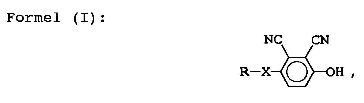


bereitgestellt wird und
die Ausrichtungsrichtung von Flüssigkristallmolekülen durch Anwendung einer Einrichtung zum Anlegen einer Spannung umgeschaltet wird, um eine Anzeige zu bewirken. - Anzeigeverfahren nach Anspruch 46, bei dem die Flüssigkristallvorrichtung ferner eine isolierende Ausrichtungseinstellungsschicht umfaßt.
- Anzeigeverfahren nach Anspruch 46, das ferner einen Schritt der Beleuchtung der Flüssigkristallvorrichtung mit Licht umfaßt.
Applications Claiming Priority (8)
| Application Number | Priority Date | Filing Date | Title |
|---|---|---|---|
| JP3523390 | 1990-02-15 | ||
| JP3523490 | 1990-02-15 | ||
| JP35234/90 | 1990-02-15 | ||
| JP35233/90 | 1990-02-15 | ||
| JP35235/90 | 1990-02-15 | ||
| JP3523590 | 1990-02-15 | ||
| JP11000/91 | 1991-01-31 | ||
| JP03011000A JP3143483B2 (ja) | 1990-02-15 | 1991-01-31 | 液晶組成物、及びこの使用方法,これを使用した液晶素子,表示装置 |
Publications (3)
| Publication Number | Publication Date |
|---|---|
| EP0442499A2 EP0442499A2 (de) | 1991-08-21 |
| EP0442499A3 EP0442499A3 (en) | 1992-08-05 |
| EP0442499B1 true EP0442499B1 (de) | 1995-09-20 |
Family
ID=27455507
Family Applications (1)
| Application Number | Title | Priority Date | Filing Date |
|---|---|---|---|
| EP91102104A Expired - Lifetime EP0442499B1 (de) | 1990-02-15 | 1991-02-14 | Flüssigkristallzusammensetzung, Flüssigkristallvorrichtung, Anzeigevorrichtung und diese verwendende Anzeigemethode |
Country Status (5)
| Country | Link |
|---|---|
| US (1) | US5217643A (de) |
| EP (1) | EP0442499B1 (de) |
| JP (1) | JP3143483B2 (de) |
| AT (1) | ATE128172T1 (de) |
| DE (1) | DE69113075T2 (de) |
Families Citing this family (8)
| Publication number | Priority date | Publication date | Assignee | Title |
|---|---|---|---|---|
| US5342544A (en) * | 1991-10-28 | 1994-08-30 | Asahi Denka Kogyo Kabushiki Kaisha | Liquid crystal composition |
| SG44527A1 (en) * | 1993-01-11 | 1997-12-19 | Chisso Corp | Liquid crystal compositions and liquid crystal display devices |
| US5858269A (en) * | 1995-09-20 | 1999-01-12 | Canon Kabushiki Kaisha | Liquid crystal device and liquid crystal apparatus |
| TWI239997B (en) * | 1998-02-04 | 2005-09-21 | Merck Patent Gmbh | Liquid-crystal composition, method of adjusting the resistance of a liquid-crystal composition, liquid-crystal display and substituted phenols |
| WO2005022244A1 (en) * | 2003-08-28 | 2005-03-10 | Koninklijke Philips Electronics N.V. | Lateral ion pumping in liquid crystal displays |
| CN101407482B (zh) * | 2008-03-27 | 2012-05-30 | 河北迈尔斯通电子材料有限公司 | 一种用于合成丁烯类液晶的中间体及其合成方法 |
| KR20180002794A (ko) * | 2015-05-04 | 2018-01-08 | 메르크 파텐트 게엠베하 | 액정 매질 |
| CN113604009B (zh) * | 2021-09-08 | 2022-11-15 | 宁波聚嘉新材料科技有限公司 | 一种高韧性液晶聚合物薄膜及其制备方法 |
Family Cites Families (14)
| Publication number | Priority date | Publication date | Assignee | Title |
|---|---|---|---|---|
| JPS5039686A (de) * | 1973-08-15 | 1975-04-11 | ||
| US4033905A (en) * | 1975-11-05 | 1977-07-05 | Rca Corporation | Method for increasing the conductivity of electrically resistive organic materials |
| US4091847A (en) * | 1976-11-22 | 1978-05-30 | Rca Corporation | Process for filling dynamic scattering liquid crystal cells |
| FR2439765A1 (fr) * | 1978-10-27 | 1980-05-23 | Thomson Csf | Compose organique mesomorphe dont la formule chimique derive d'un acide alcoxy-4 tetrafluorobenzoique, et dispositif a cristal liquide utilisant un tel compose |
| GB2094311A (en) * | 1980-08-22 | 1982-09-15 | Ivaschenko Aleksandr Vasilevic | New derivatives of phenic acid method of obtaining them liquid crystal material with negative dielectric anisotropy method of obtaining that liquid crystal material liquid crystal material with low frequency in version of sign of dielectric anisotropy and method of obtaining that liquid crystal material |
| FR2503703A1 (fr) * | 1981-04-08 | 1982-10-15 | Ivaschenko Alexandr | Nouveaux derives du phenol, leur procede de preparation, materiau a base de cristaux liquides a anisotropie dielectrique negative, procede de preparation de ce materiau, materiau a base de cristaux liquides a inversion basse frequence du signe d'anisotropie dielectrique et procede de preparation de ce dernier |
| JPH0623156B2 (ja) * | 1982-02-25 | 1994-03-30 | 三菱化成株式会社 | フタロニトリル誘導体 |
| JPH0833560B2 (ja) * | 1986-11-27 | 1996-03-29 | キヤノン株式会社 | 液晶素子 |
| DE3712817A1 (de) * | 1987-04-15 | 1988-10-27 | Bayer Ag | Verwendung von fluormethylphenolen als loesungsmittel fuer lc-polymere, und neue fluormethylphenole |
| JP2710779B2 (ja) * | 1987-06-03 | 1998-02-10 | 株式会社クラレ | 高分子液晶化合物への電場印加方法 |
| JPS6478235A (en) * | 1987-09-19 | 1989-03-23 | Canon Kk | Ferroelectric liquid crystal element |
| JPS6490413A (en) * | 1987-09-30 | 1989-04-06 | Idemitsu Kosan Co | Non-linear optical device |
| US4909598A (en) * | 1988-07-30 | 1990-03-20 | Konica Corporation | Non-linear optical device |
| KR900701959A (ko) * | 1988-08-31 | 1990-12-05 | 호이만, 쉬틀러 | 열색 혼합물 |
-
1991
- 1991-01-31 JP JP03011000A patent/JP3143483B2/ja not_active Expired - Fee Related
- 1991-02-11 US US07/653,233 patent/US5217643A/en not_active Expired - Fee Related
- 1991-02-14 EP EP91102104A patent/EP0442499B1/de not_active Expired - Lifetime
- 1991-02-14 AT AT91102104T patent/ATE128172T1/de active
- 1991-02-14 DE DE69113075T patent/DE69113075T2/de not_active Expired - Fee Related
Also Published As
| Publication number | Publication date |
|---|---|
| DE69113075T2 (de) | 1996-03-28 |
| ATE128172T1 (de) | 1995-10-15 |
| EP0442499A3 (en) | 1992-08-05 |
| US5217643A (en) | 1993-06-08 |
| JP3143483B2 (ja) | 2001-03-07 |
| JPH04211492A (ja) | 1992-08-03 |
| DE69113075D1 (de) | 1995-10-26 |
| EP0442499A2 (de) | 1991-08-21 |
Similar Documents
| Publication | Publication Date | Title |
|---|---|---|
| US4856875A (en) | Liquid-crystal display devices of twisted nematic type | |
| US5194179A (en) | Liquid crystal compounds | |
| EP0694599B1 (de) | Flüssigkristallzusammensetzung, -vorrichtung, -apparat und Anzeigeverfahren, die sie verwenden | |
| EP0442499B1 (de) | Flüssigkristallzusammensetzung, Flüssigkristallvorrichtung, Anzeigevorrichtung und diese verwendende Anzeigemethode | |
| JPS6055078A (ja) | 液晶組成物 | |
| EP0829468A1 (de) | Verbindungen enthaltend ein Schwalbenschwanz-Endstück und sie enthaltende ferrielektrische flüssigkristalline Zusammensetzung | |
| US5688437A (en) | Liquid crystal composition, liquid crystal device using the composition, liquid crystal apparatus and display method | |
| JPH0762349A (ja) | スメクチック液晶混合物 | |
| EP0469893B1 (de) | Fluorierte Pyrimidin-Phenyl optisch aktive Verbindungen und sie enthaltende flüssigkristalline Zusammensetzungen | |
| JP4731014B2 (ja) | 単安定強誘電性アクティブマトリックスディスプレイ | |
| US5858269A (en) | Liquid crystal device and liquid crystal apparatus | |
| JP2001511470A (ja) | アクティブマトリクス素子を有する強誘電性液晶ディスプレイ | |
| JP2732765B2 (ja) | 強誘電性液晶表示素子 | |
| JP3453781B2 (ja) | ネマチック液晶組成物及びこれを用いた液晶表示装置 | |
| JPS6348259B2 (de) | ||
| US4981967A (en) | Pyrimidine compounds and their use as liquid crystals | |
| JPH10120629A (ja) | フェニルエステル化合物及びそれを含むフェリ誘電性液晶組成物 | |
| JPH1150054A (ja) | フェリ誘電性液晶組成物 | |
| JP3216752B2 (ja) | 光学活性化合物、それを含有する液晶組成物、それを有する液晶素子及びそれらを用いた表示方法、表示装置 | |
| JPH0424345B2 (de) | ||
| JP2726111B2 (ja) | 強誘電性液晶素子 | |
| JPH0778042B2 (ja) | ピリミジン化合物 | |
| JP2946792B2 (ja) | 2,3−ジシアノヒドロキノン誘導体および液晶組成物および液晶表示素子 | |
| JPH10245364A (ja) | フェニルエステル化合物及びそれを含むフェリ誘電性液晶組成物 | |
| KR19990072773A (ko) | 페리유전성액정화합물 |
Legal Events
| Date | Code | Title | Description |
|---|---|---|---|
| PUAI | Public reference made under article 153(3) epc to a published international application that has entered the european phase |
Free format text: ORIGINAL CODE: 0009012 |
|
| 17P | Request for examination filed |
Effective date: 19910214 |
|
| AK | Designated contracting states |
Kind code of ref document: A2 Designated state(s): AT BE CH DE DK ES FR GB GR IT LI LU NL SE |
|
| PUAL | Search report despatched |
Free format text: ORIGINAL CODE: 0009013 |
|
| AK | Designated contracting states |
Kind code of ref document: A3 Designated state(s): AT BE CH DE DK ES FR GB GR IT LI LU NL SE |
|
| 17Q | First examination report despatched |
Effective date: 19931210 |
|
| GRAA | (expected) grant |
Free format text: ORIGINAL CODE: 0009210 |
|
| AK | Designated contracting states |
Kind code of ref document: B1 Designated state(s): AT BE CH DE DK ES FR GB GR IT LI LU NL SE |
|
| PG25 | Lapsed in a contracting state [announced via postgrant information from national office to epo] |
Ref country code: GR Free format text: LAPSE BECAUSE OF FAILURE TO SUBMIT A TRANSLATION OF THE DESCRIPTION OR TO PAY THE FEE WITHIN THE PRESCRIBED TIME-LIMIT Effective date: 19950920 Ref country code: ES Free format text: THE PATENT HAS BEEN ANNULLED BY A DECISION OF A NATIONAL AUTHORITY Effective date: 19950920 Ref country code: DK Effective date: 19950920 Ref country code: BE Effective date: 19950920 Ref country code: AT Effective date: 19950920 |
|
| REF | Corresponds to: |
Ref document number: 128172 Country of ref document: AT Date of ref document: 19951015 Kind code of ref document: T |
|
| REF | Corresponds to: |
Ref document number: 69113075 Country of ref document: DE Date of ref document: 19951026 |
|
| ET | Fr: translation filed | ||
| ITF | It: translation for a ep patent filed | ||
| PG25 | Lapsed in a contracting state [announced via postgrant information from national office to epo] |
Ref country code: LU Free format text: LAPSE BECAUSE OF NON-PAYMENT OF DUE FEES Effective date: 19960229 |
|
| PLBE | No opposition filed within time limit |
Free format text: ORIGINAL CODE: 0009261 |
|
| STAA | Information on the status of an ep patent application or granted ep patent |
Free format text: STATUS: NO OPPOSITION FILED WITHIN TIME LIMIT |
|
| 26N | No opposition filed | ||
| REG | Reference to a national code |
Ref country code: GB Ref legal event code: IF02 |
|
| PGFP | Annual fee paid to national office [announced via postgrant information from national office to epo] |
Ref country code: SE Payment date: 20030205 Year of fee payment: 13 |
|
| PGFP | Annual fee paid to national office [announced via postgrant information from national office to epo] |
Ref country code: FR Payment date: 20030210 Year of fee payment: 13 |
|
| PGFP | Annual fee paid to national office [announced via postgrant information from national office to epo] |
Ref country code: GB Payment date: 20030212 Year of fee payment: 13 |
|
| PGFP | Annual fee paid to national office [announced via postgrant information from national office to epo] |
Ref country code: CH Payment date: 20030214 Year of fee payment: 13 |
|
| PGFP | Annual fee paid to national office [announced via postgrant information from national office to epo] |
Ref country code: NL Payment date: 20030226 Year of fee payment: 13 |
|
| PGFP | Annual fee paid to national office [announced via postgrant information from national office to epo] |
Ref country code: DE Payment date: 20030227 Year of fee payment: 13 |
|
| PG25 | Lapsed in a contracting state [announced via postgrant information from national office to epo] |
Ref country code: GB Free format text: LAPSE BECAUSE OF NON-PAYMENT OF DUE FEES Effective date: 20040214 |
|
| PG25 | Lapsed in a contracting state [announced via postgrant information from national office to epo] |
Ref country code: SE Free format text: LAPSE BECAUSE OF NON-PAYMENT OF DUE FEES Effective date: 20040215 |
|
| PG25 | Lapsed in a contracting state [announced via postgrant information from national office to epo] |
Ref country code: LI Free format text: LAPSE BECAUSE OF NON-PAYMENT OF DUE FEES Effective date: 20040229 Ref country code: CH Free format text: LAPSE BECAUSE OF NON-PAYMENT OF DUE FEES Effective date: 20040229 |
|
| PG25 | Lapsed in a contracting state [announced via postgrant information from national office to epo] |
Ref country code: NL Free format text: LAPSE BECAUSE OF NON-PAYMENT OF DUE FEES Effective date: 20040901 Ref country code: DE Free format text: LAPSE BECAUSE OF NON-PAYMENT OF DUE FEES Effective date: 20040901 |
|
| EUG | Se: european patent has lapsed | ||
| GBPC | Gb: european patent ceased through non-payment of renewal fee |
Effective date: 20040214 |
|
| REG | Reference to a national code |
Ref country code: CH Ref legal event code: PL |
|
| PG25 | Lapsed in a contracting state [announced via postgrant information from national office to epo] |
Ref country code: FR Free format text: LAPSE BECAUSE OF NON-PAYMENT OF DUE FEES Effective date: 20041029 |
|
| NLV4 | Nl: lapsed or anulled due to non-payment of the annual fee |
Effective date: 20040901 |
|
| REG | Reference to a national code |
Ref country code: FR Ref legal event code: ST |
|
| PG25 | Lapsed in a contracting state [announced via postgrant information from national office to epo] |
Ref country code: IT Free format text: LAPSE BECAUSE OF NON-PAYMENT OF DUE FEES;WARNING: LAPSES OF ITALIAN PATENTS WITH EFFECTIVE DATE BEFORE 2007 MAY HAVE OCCURRED AT ANY TIME BEFORE 2007. THE CORRECT EFFECTIVE DATE MAY BE DIFFERENT FROM THE ONE RECORDED. Effective date: 20050214 |