EP0442487A2 - Connecting element for two construction frame members - Google Patents
Connecting element for two construction frame members Download PDFInfo
- Publication number
- EP0442487A2 EP0442487A2 EP91102067A EP91102067A EP0442487A2 EP 0442487 A2 EP0442487 A2 EP 0442487A2 EP 91102067 A EP91102067 A EP 91102067A EP 91102067 A EP91102067 A EP 91102067A EP 0442487 A2 EP0442487 A2 EP 0442487A2
- Authority
- EP
- European Patent Office
- Prior art keywords
- connecting element
- spring
- spring tongue
- element according
- locking
- Prior art date
- Legal status (The legal status is an assumption and is not a legal conclusion. Google has not performed a legal analysis and makes no representation as to the accuracy of the status listed.)
- Granted
Links
Images
Classifications
-
- E—FIXED CONSTRUCTIONS
- E04—BUILDING
- E04B—GENERAL BUILDING CONSTRUCTIONS; WALLS, e.g. PARTITIONS; ROOFS; FLOORS; CEILINGS; INSULATION OR OTHER PROTECTION OF BUILDINGS
- E04B2/00—Walls, e.g. partitions, for buildings; Wall construction with regard to insulation; Connections specially adapted to walls
- E04B2/88—Curtain walls
- E04B2/96—Curtain walls comprising panels attached to the structure through mullions or transoms
- E04B2/967—Details of the cross-section of the mullions or transoms
Definitions
- the invention relates to a releasable, the static connection function taking over connecting element between two frame components, in particular an inner and outer post or transom of a mullion-transom facade, each of which faces a mutually facing, undercut on both sides, extending in the longitudinal direction of the profile for the positive reception of one end have the connecting element.
- the connecting element has a rotating part which can be rotated manually from the outside via a handle about its longitudinal axis in the coupling or decoupling position, in its coupling position at one end with a hammer head in an undercut groove and at its other end with anchoring means in the engages other undercut groove and can be locked in this coupling position by a rotation lock.
- the anchoring means have a slider which is arranged to be longitudinally displaceable in the groove and carries the rotating part.
- the handle consists of a spring-elastic element that is non-rotatably connected to the rotating part, which protrudes between the two components in the uncoupling position and engages behind a holder in the coupling position under bending stress.
- the invention has for its object to develop an easily assembled and non-destructively removable connector that not only takes over the static connection function between the two frame components, but also their thermal separation.
- each spring tongue has a nose-shaped or strip-shaped handle, which is a shorter distance from the other end of the connecting element in comparison to the latching nose has and protrudes in the coupling position over the outer contour of the body.
- the handle is therefore outside the assigned undercut groove of the frame component and is therefore freely accessible to a tool.
- the connecting element is characterized according to the invention by a flat, square or rectangular body which has on its two opposite flat sides each a plurality of spring tongues, each arranged in a row at a distance from one another, each around the opposite row of spring tongues about half a spring tongue distance are arranged offset. Due to the offset arrangement of the spring tongues, the connecting element can be kept very flat, which has a positive effect on the thermal separation.
- the handling that protrudes on both flat sides of the connecting element can be done with a tool, e.g. a flat iron, act together so that the associated frame component can be removed in a simple manner without destruction.
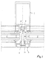
- FIG. 1 shows an inner post 1, preferably formed by an aluminum profile, which is connected to an outer post 3 via a releasable connecting element 2, which takes over the static connection function, which also preferably consists of an aluminum profile.
- Two insulating glazings 4 are clamped between the inner and outer posts 1, 3.
- Inner and outer posts 1, 3 each have a mutually facing, undercut groove 5 and 6 in the longitudinal direction of the profile, for the positive reception of one end of the connecting element 2.
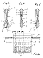
- the connecting element 2 shown in more detail in FIGS. 2 to 5 is made of plastic and has a flat body 7 which is at least approximately square in accordance with FIG. 2 and which is equipped at its lower end in the figures with spring tongues 9 forming a releasable coupling.
- These spring tongues 9 are on the two opposite flat sides 8 of the body 7 arranged in a row next to each other at a distance, the two rows of spring tongues lying opposite one another being offset from one another by about half the spring tongue distance, so that each spring tongue is arranged between two opposite spring tongues.
- Each spring tongue 9 can be pivoted about its spring tongue foot 10 lying at the extreme end of the body 7 into an inner cavity 11 of the body 7 into a decoupling position, specifically against the action of a counter spring 12 projecting into this cavity 11.
- Each spring tongue 9 is equipped with a latching lug 13 which, in the coupling position of the spring tongue 9, projects beyond the outer contour of the body 7 and engages behind the associated undercut groove 6 of the outer post 3 (see FIG. 1).
- each spring tongue 9 is pressed against the action of the counter spring 12 acting on it into said cavity 11 until the counter spring 12 engages behind the free end of the spring tongue 9 in a locking manner.
- a recess 14 is provided at the free end of each spring tongue 9, in which the counter spring 12 can engage in a locking manner.
- the latching lug 13 then lies at least largely within the outer contour of the body 7, so that the one end of the connecting element 2 can be pulled out of the groove 6 of the outer post 3.
- each spring tongue 9 has a nose-shaped or strip-shaped handle 15, which has a shorter distance from the other end of the connecting element 2 in comparison to the latching lug 13 and which is shown in FIG. 1 Clutch position protrudes beyond the outer contour of the body 7. This makes it possible, without optical control and complex manipulation, for example with flat-nose pliers, to simultaneously press the opposing spring tongues 9 into their unlocked position in the cavity 11 of the connecting element 2, where the spring tongues 9 are then automatically locked by the associated counter springs 12.
- the upper end of the connecting element 2 is designed as a resilient fork, the two spring tines 16 of which can be pressed resiliently against one another at their free end each have a detent 17 projecting in a spread coupling position over the outer contour of the body 7, which in the coupling position has the associated one reach behind the undercut groove 5 of the inner post 1 on both sides.
- the connecting element 2 is inserted with its fork tines 16 into the groove 5, the bevels provided on the latching lugs 17 leading to a compression of the fork tines 16 when the connecting element 2 is pushed in, which automatically reach the locking position when the groove bottom is reached due to their inherent elasticity rebound.
- the bolts 18 indicated in FIG. 2 are inserted between the fork tines 16.
- the bolts 18 can have longitudinal teeth 19 and can be fixed in their locking position by local brackets 20.
- the connecting element 2 combines both a thermal separation and a static connection of the metal components 1, 3, without thereby generating new cold bridges. Nevertheless, it is an easily detachable connection that can be dismantled e.g. of the outer post 3 enables without destruction.
- the spring tongues 9 engage behind the undercut groove 6 on both sides, i.e. for decoupling the spring tongues 9 provided on both flat sides 8 of the connecting element 2 must be pressed into the body 7, this body can be made very flat due to the offset arrangement of the spring tongues 9 and has in a special embodiment has a thickness of only 11.5 mm. This enables very favorable values for the thermal separation of the frame profiles.
- each spring tongue 9 lies outside the groove 6, the handles 15 are easily accessible to a tool.
Abstract
Description
Die Erfindung betrifft ein lösbares, die statische verbindungsfunktion übernehmendes Verbindungselement zwischen zwei Rahmenbauteilen, insbesondere einem Innen- und Außenpfosten bzw. Riegel einer Pfosten-Riegel-Fassade, die je eine einander zugewandte, beidseitig hinterschnittene, in Profillängsrichtung verlaufende Nut zur formschlüssigen Aufnahme je eines Endes des verbindungselementes aufweisen.The invention relates to a releasable, the static connection function taking over connecting element between two frame components, in particular an inner and outer post or transom of a mullion-transom facade, each of which faces a mutually facing, undercut on both sides, extending in the longitudinal direction of the profile for the positive reception of one end have the connecting element.
Eine derartige Ausführungsform läßt sich der DE-C1-35 39 003 entnehmen. Das Verbindungselement weist ein Drehteil auf, das von außen manuell über eine Handhabe um seine Längsachse in Kupplungs- bzw. Entkupplungsstellung drehbar ist, in seiner Kupplungsstellung an seinem einen Ende mit einem Hammerkopf in die eine hinterschnittene Nut und an seinem anderen Ende mit Verankerungsmitteln in die andere hinterschnittene Nut eingreift und in dieser Kupplungsstellung durch eine Drehsicherung arretierbar ist. Die Verankerungsmittel weisen ein Gleitstück auf, das in der Nut längsverschiebbar angeordnet ist und das Drehteil trägt. Die Handhabe besteht aus einem federelastischen, drehfest mit dem Drehteil verbundenen Element, das in Entkupplungsstellung zwischen den beiden Bauteilen herausragt und in Kupplungsstellung unter Biegespannung eine Halterung hintergreift.Such an embodiment can be found in DE-C1-35 39 003. The connecting element has a rotating part which can be rotated manually from the outside via a handle about its longitudinal axis in the coupling or decoupling position, in its coupling position at one end with a hammer head in an undercut groove and at its other end with anchoring means in the engages other undercut groove and can be locked in this coupling position by a rotation lock. The anchoring means have a slider which is arranged to be longitudinally displaceable in the groove and carries the rotating part. The handle consists of a spring-elastic element that is non-rotatably connected to the rotating part, which protrudes between the two components in the uncoupling position and engages behind a holder in the coupling position under bending stress.
Der Erfindung liegt die Aufgabe zugrunde, ein leicht montierbares und zerstörungsfrei demontierbares Verbindungselement zu entwickeln, das nicht nur die statische Verbindungsfunktion zwischen den beiden Rahmenbauteilen, sondern auch noch deren thermische Trennung übernimmt.The invention has for its object to develop an easily assembled and non-destructively removable connector that not only takes over the static connection function between the two frame components, but also their thermal separation.
Diese Aufgabe wird erfindungsgemäß durch folgende Merkmale gelöst:
- a) Das Verbindungselement besteht aus Kunststoff;
- b) das eine Ende des Verbindungselementes weist eine lösbare Kupplung bildende Federzungen auf, die mit je einer Rastnase bestückt sind, die in Kupplungsstellung über die Außenkontur des Körpers vorstehen, um die zugeordnete hinterschnittene Nut beidseitig verriegelnd zu hintergreifen;
- c) jede Federzunge ist gegen die Wirkung einer in einen inneren Hohlraum des Körpers ragende Gegenfeder in diesen Hohlraum hinein verschwenkbar in eine Entkupplungsstellung, in der die Rastnase zumindest weitgehend innerhalb der Außenkontur des Körpers liegt;
- d) in einer Entkupplungsstellung wird die Federzunge durch die das freie Ende der Federzunge hintergreifende Gegenfeder automatisch arretiert.
- a) The connecting element is made of plastic;
- b) the one end of the connecting element has a releasable coupling spring tongues, which are each equipped with a locking lug, which protrude beyond the outer contour of the body in the coupling position in order to engage behind the associated undercut groove in a locking manner on both sides;
- c) each spring tongue can be pivoted against the action of a counter spring projecting into an inner cavity of the body into this cavity into a decoupling position in which the latching lug lies at least largely within the outer contour of the body;
- d) in a decoupling position, the spring tongue is automatically locked by the counter spring engaging behind the free end of the spring tongue.
Um das Verschwenken der Federzungen in ihre Entkupplungsstellung zu erleichtern und z.B. mit einem Werkzeug durchführen zu können, ist es zweckmäßig, wenn jede Federzunge einen nasen- bzw. leistenförmige Handhabe aufweist, die im Vergleich zur Rastnase einen kürzeren Abstand vom anderen Ende des Verbindungselementes aufweist und in Kupplungsstellung über die Außenkontur des Körpers vorsteht. Die Handhabe liegt also außerhalb der zugeordneten hinterschnittenen Nut des Rahmenbauteils und ist daher einem Werkzeug frei zugänglich.In order to facilitate the pivoting of the spring tongues into their uncoupling position and, for example, to be able to carry them out with a tool, it is expedient if each spring tongue has a nose-shaped or strip-shaped handle, which is a shorter distance from the other end of the connecting element in comparison to the latching nose has and protrudes in the coupling position over the outer contour of the body. The handle is therefore outside the assigned undercut groove of the frame component and is therefore freely accessible to a tool.
Zur Optimierung der thermischen Trennung ist das Verbindungselement erfindungsgemäß gekennzeichnet durch einen flachen, quadratisch oder rechteckig ausgebildeten Körper, der auf seinen beiden sich gegenüberliegenden Flachseiten jeweils mehrere, in je einer Reihe mit Abstand nebeneinander angeordnete Federzungen aufweist, die gegenüber der gegenüberliegenden Federzungen-Reihe jeweils um etwa einen halben Federzungenabstand versetzt angeordnet sind. Durch die versetzte Anordnung der Federzungen kann das Verbindungselement sehr flach gehalten werden, was sich hinsichtlich der thermischen Trennung positiv auswirkt. Die auf beiden Flachseiten des Verbindungselementes herausragenden Handhabungen lassen sich mit einem Werkzeug, z.B. einem Flacheisen, gemeinsam beaufschlagen, so daß sich das zugeordnete Rahmenbauteil in einfacher Weise ohne Zerstörung abnehmen läßt.To optimize the thermal separation, the connecting element is characterized according to the invention by a flat, square or rectangular body which has on its two opposite flat sides each a plurality of spring tongues, each arranged in a row at a distance from one another, each around the opposite row of spring tongues about half a spring tongue distance are arranged offset. Due to the offset arrangement of the spring tongues, the connecting element can be kept very flat, which has a positive effect on the thermal separation. The handling that protrudes on both flat sides of the connecting element can be done with a tool, e.g. a flat iron, act together so that the associated frame component can be removed in a simple manner without destruction.
Weitere Merkmale der Erfindung sind Gegenstand der Unteransprüche und werden in Verbindung mit weiteren Vorteilen der Erfindung anhand eines Ausführungsbeispieles näher erläutert.Further features of the invention are the subject of the dependent claims and are explained in connection with further advantages of the invention using an exemplary embodiment.
In der Zeichnung ist eine als Beispiel dienende Ausführungsform der Erfindung dargestellt. Es zeigen:
Figur 1 einen Horizontalschnitt durch den Pfosten einer Pfosten-Riegel-Fassade;Figur 2 ein inFigur 1 in Draufsicht dargestelltes Verbindungselement in Seitenansicht;Figur 3 einen Schnitt gemäß der Linie III inFigur 2;Figur 4 einen Schnitt gemäß der Linie IV inFigur 2 undFigur 5 einen Schnitt gemäß der Linie V inFigur 2.
- Figure 1 shows a horizontal section through the post of a mullion-transom facade;
- Figure 2 is a side view of a connecting element shown in Figure 1 in plan view;
- 3 shows a section along the line III in Figure 2;
- 4 shows a section along the line IV in Figure 2 and
- 5 shows a section along the line V in Figure 2.
Figur 1 zeigt einen vorzugsweise durch ein Aluminiumprofil gebildeten Innenpfosten 1, der über ein lösbares, die statische Verbindungsfunktion übernehmendes Verbindungselement 2 mit einem Außenpfosten 3 verbunden ist, der ebenfalls vorzugsweise aus einem Aluminiumprofil besteht. Zwischen Innen- und Außenpfosten 1,3 sind zwei Isolierverglasungen 4 eingespannt. Innen- und Außenpfosten 1,3 weisen je eine einander zugewandte, beidseitig hinterschnittene, in Profillängsrichtung verlaufende Nut 5 bzw. 6 auf zur formschlüssigen Aufnahme je eines Endes des Verbindungselementes 2.FIG. 1 shows an
Das in den Figuren 2 bis 5 näher dargestellte Verbindungselement 2 besteht aus Kunststoff und weist einen flachen, gemäß Figur 2 zumindest angenähert quadratisch ausgebildeten Körper 7 auf, der an seinem in den Figuren jeweils unten liegenden Ende mit eine lösbare Kupplung bildenden Federzungen 9 bestückt ist. Diese Federzungen 9 sind auf den beiden sich gegenüberliegenden Flachseiten 8 des Körpers 7 in jeweils einer Reihe mit Abstand nebeneinander angeordnet, wobei die beiden sich gegenüberliegenden Federzungen-Reihen um etwa einen halben Federzungen-Abstand gegeneinander versetzt angeordnet sind, so daß jede Federzunge zwischen zwei gegenüberliegenden Federzungen angeordnet ist.The connecting
Jede Federzunge 9 ist um ihren am äußersten einen Ende des Körpers 7 liegenden Federzungen-Fuß 10 in einen inneren Hohlraum 11 des Körpers 7 hinein in eine Entkupplungsstellung verschwenkbar und zwar gegen die Wirkung einer in diesen Hohlraum 11 ragenden Gegenfeder 12.Each
Jede Federzunge 9 ist mit einer Rastnase 13 bestückt, die in Kupplungsstellung der Federzunge 9 über die Außenkontur des Körpers 7 vorsteht und die zugeordnete hinterschnittene Nut 6 des Außenpfostens 3 verriegelnd hintergreift (siehe Figur 1). Zur Entkupplung wird jede Federzunge 9 gegen die Wirkung der sie beaufschlagenden Gegenfeder 12 in den genannten Hohlraum 11 soweit eingedrückt, bis die Gegenfeder 12 das freie Ende der Federzunge 9 verriegelnd hintergreift. Zur eindeutigen Definition dieser Entkupplungsstellung ist am freien Ende jeder Federzunge 9 eine Ausnehmung 14 vorgesehen, in die die Gegenfeder 12 verriegelnd eingreifen kann. In dieser Entkupplungsstellung liegt dann die Rastnase 13 zumindest weitgehend innerhalb der Außenkontur des Körpers 7, so daß das Verbindungselement 2 mit seinem einen Ende aus der Nut 6 des Außenpfostens 3 herausgezogen werden kann.Each
Um das Eindrücken der Federzungen 9 in ihre Entriegelungsstellung zu vereinfachen, weist jede Federzunge 9 eine nasen- bzw. leistenförmige Handhabe 15 auf, die im Vergleich zur Rastnase 13 einen kürzeren Abstand von dem anderen Ende des Verbindungselementes 2 aufweist und in der in Figur 1 dargestellten Kupplungsstellung über die Außenkontur des Körpers 7 vorsteht. Dadurch ist es möglich, ohne optische Kontrolle und aufwendige Manipulation beispielsweise mit einer Flachzange die sich gegenüberliegenden Federzungen 9 gleichzeitig in ihre Entriegelungsstellung in den Hohlraum 11 des Verbindungselementes 2 hineinzudrücken, wo dann eine automatische Arretierung aller Federzungen 9 durch die zugeordneten Gegenfedern 12 erfolgt.In order to simplify the pushing-in of the
Das andere, in den Figuren jeweils obere Ende des Verbindungselementes 2 ist als federnde Gabel ausgebildet, deren beiden federelastisch gegeneinander drückbaren Gabelzinken 16 an ihrem freien Ende je eine in gespreizter Kupplungsstellung über die Außenkontur des Körpers 7 vorstehende Rastnase 17 aufweisen, die in Kupplungsstellung die zugeordnete hinterschnittene Nut 5 des Innenpfostens 1 beidseitig verriegelnd hintergreifen. Zur Herstellung der Verbindung wird das Verbindungselement 2 mit seinen Gabelzinken 16 in die Nut 5 eingeschoben, wobei die an den Rastnasen 17 vorgesehenen Anlaufschrägen beim Einschieben des Verbindungselementes 2 zu einem Zusammendrücken der Gabelzinken 16 führen, die bei Erreichen des Nutgrundes aufgrund ihrer Eigenelastizität selbsttätig in Verriegelungsstellung ausfedern. Zur Arretierung dieser Kupplungsstellung werden die in Figur 2 angedeuteten Bolzen 18 zwischen die Gabelzinken 16 eingeschoben. Die Bolzen 18 können eine Längsverzahnung 19 aufweisen und durch örtliche Halterungen 20 in ihre Arretierungsstellung fixiert werden.The other, in the figures, the upper end of the connecting
Die Verriegelung des mit den Federzungen 9 bestückten Endes des Verbindungselementes 2 mit der Nut 6 des Außenpfostens 3 erfolgt ebenfalls durch bloßes Einschieben des Verbindungselementes 2, wodurch die mit Auflaufschrägen versehenen Federzungen 9 nach innen gedrückt werden, um nach Erreichen des Nutgrundes wieder ausfedern zu können. Dieses Eindrücken der Federzungen 9 erfolgt zwar gegen die Wirkung der Gegenfedern 12, jedoch nur soweit in den Hohlraum 11 hinein, daß die Gegenfedern 12 den freien Rand der Federzunge 9 noch nicht verriegelnd hintergreifen können.The locking of the end of the connecting
Zur Querschnittsverringerung sind in dem Körper 7 des Verbindungselementes 2 Hohlkammern 21 angeordnet. In Figur 2 sind die massiven Trennstege zwischen den einzelnen Federzungen 9 mit dem Bezugszeichen 22 gekennzeichnet.To reduce the cross-section, 2
Das Verbindungselement 2 vereinigt in sich sowohl eine thermische Trennung als auch eine statische Verbindung der aus Metall bestehenden Bauteile 1,3 , ohne hierbei neue Kältebrücken zu erzeugen. Dennoch handelt es sich um eine leicht lösbare Verbindung, die die Demontage z.B. des Außenpfostens 3 ohne Zerstörung ermöglicht. Obwohl die Federzungen 9 die hinterschnittene Nut 6 beidseitig hintergreifen, also zur Entkupplung die auf beiden Flachseiten 8 des Verbindungselementes 2 vorgesehenen Federzungen 9 in den Körper 7 eingedrückt werden müssen, kann dieser Körper aufgrund der versetzten Anordnung der Federzungen 9 sehr flach ausgebildet werden und weist in einem speziellen Ausführungsbeispiel eine Dicke von nur 11,5 mm auf. Dies ermöglicht sehr günstige Werte für die thermische Trennung der Rahmenprofile.The connecting
Da die Handhabe 15 jeder Federzunge 9 außerhalb der Nut 6 liegt, sind die Handhaben 15 einem Werkzeug ohne weiteres zugänglich.Since the
Claims (8)
Applications Claiming Priority (2)
| Application Number | Priority Date | Filing Date | Title |
|---|---|---|---|
| DE4004586 | 1990-02-15 | ||
| DE4004586A DE4004586A1 (en) | 1990-02-15 | 1990-02-15 | CONNECTING ELEMENT BETWEEN TWO FRAME COMPONENTS |
Publications (3)
| Publication Number | Publication Date |
|---|---|
| EP0442487A2 true EP0442487A2 (en) | 1991-08-21 |
| EP0442487A3 EP0442487A3 (en) | 1992-03-04 |
| EP0442487B1 EP0442487B1 (en) | 1993-05-26 |
Family
ID=6400148
Family Applications (1)
| Application Number | Title | Priority Date | Filing Date |
|---|---|---|---|
| EP91102067A Expired - Lifetime EP0442487B1 (en) | 1990-02-15 | 1991-02-14 | Connecting element for two construction frame members |
Country Status (4)
| Country | Link |
|---|---|
| EP (1) | EP0442487B1 (en) |
| AT (1) | ATE89886T1 (en) |
| DE (2) | DE4004586A1 (en) |
| DK (1) | DK0442487T3 (en) |
Cited By (5)
| Publication number | Priority date | Publication date | Assignee | Title |
|---|---|---|---|---|
| WO1999058782A1 (en) * | 1998-05-11 | 1999-11-18 | Naimon Investments Limited | Panel assembly |
| WO2004088170A1 (en) * | 2003-04-04 | 2004-10-14 | Murtfeldt Kunstostoffe Gmbh & Co. Kg | Method and device for connecting two profiled members having a different function |
| WO2018114353A1 (en) * | 2016-12-21 | 2018-06-28 | Frener & Reifer Gmbh / Srl | Fastening element for façade mullion-transom system, and façade mullion-transom system |
| CN112031219A (en) * | 2020-05-27 | 2020-12-04 | 浙江斯泰新材料科技股份有限公司 | Groove type embedded part and manufacturing method thereof |
| CN112982759A (en) * | 2021-03-12 | 2021-06-18 | 中建八局第二建设有限公司 | Novel energy-saving system of super high-rise unit type curtain wall |
Families Citing this family (9)
| Publication number | Priority date | Publication date | Assignee | Title |
|---|---|---|---|---|
| DE4105208C2 (en) * | 1991-02-20 | 1997-08-07 | Trube & Kings Kg | Mullion or transom profile for building facade constructions |
| DE29612381U1 (en) * | 1996-07-23 | 1996-09-12 | Knak Ulrich Joachim | Device for the thermally insulated fastening of flat components |
| EP0821127A3 (en) * | 1996-07-23 | 1998-09-16 | Ulrich Knak | Device for fixing of flat construction elements in a thermally insulated way |
| DE19833029C2 (en) * | 1997-07-25 | 2001-05-31 | Linnenbrink Hans Josef | Front frame for doors with a cutout |
| DE10058159A1 (en) * | 2000-11-22 | 2002-05-23 | Gunvar Blanck | Facing construction for building has separating element with low heat conductivity located between adjoining facing elements, with separating element formed by beam and facing elements by rectangular panels with double glazing |
| DE20305555U1 (en) * | 2003-04-04 | 2004-07-01 | Murtfeldt Kunststoffe Gmbh & Co. Kg | Connecting system for attaching chain guide rail to plastic support rail comprises T-shaped connector with arms which fit into groove in the support rail and whose top fits into T-shaped groove in guide rail |
| DE102004016215B4 (en) * | 2004-04-01 | 2008-11-06 | Frener & Reifer - Metallbau Gmbh | Mullion-transom system with low view width |
| WO2010126433A1 (en) * | 2009-04-28 | 2010-11-04 | Ge Healthcare Bio-Sciences Ab | An attachment arrangement for a column holder |
| SE2151599A1 (en) * | 2021-12-22 | 2023-06-23 | Bark Fasadsystem Ab | Construction system comprising carrying profile and an isolating element |
Citations (2)
| Publication number | Priority date | Publication date | Assignee | Title |
|---|---|---|---|---|
| US4008552A (en) * | 1973-07-11 | 1977-02-22 | Howmet Corporation | Wall structure and elements therefor |
| US4428171A (en) * | 1982-03-12 | 1984-01-31 | Atlantic Richfield Company | Thermal storefront system |
Family Cites Families (1)
| Publication number | Priority date | Publication date | Assignee | Title |
|---|---|---|---|---|
| DE3539003C1 (en) * | 1985-11-02 | 1987-01-15 | Eltreva Ag | Frame construction |
-
1990
- 1990-02-15 DE DE4004586A patent/DE4004586A1/en not_active Withdrawn
-
1991
- 1991-02-14 DE DE9191102067T patent/DE59100124D1/en not_active Expired - Fee Related
- 1991-02-14 AT AT91102067T patent/ATE89886T1/en not_active IP Right Cessation
- 1991-02-14 DK DK91102067.5T patent/DK0442487T3/en active
- 1991-02-14 EP EP91102067A patent/EP0442487B1/en not_active Expired - Lifetime
Patent Citations (2)
| Publication number | Priority date | Publication date | Assignee | Title |
|---|---|---|---|---|
| US4008552A (en) * | 1973-07-11 | 1977-02-22 | Howmet Corporation | Wall structure and elements therefor |
| US4428171A (en) * | 1982-03-12 | 1984-01-31 | Atlantic Richfield Company | Thermal storefront system |
Cited By (5)
| Publication number | Priority date | Publication date | Assignee | Title |
|---|---|---|---|---|
| WO1999058782A1 (en) * | 1998-05-11 | 1999-11-18 | Naimon Investments Limited | Panel assembly |
| WO2004088170A1 (en) * | 2003-04-04 | 2004-10-14 | Murtfeldt Kunstostoffe Gmbh & Co. Kg | Method and device for connecting two profiled members having a different function |
| WO2018114353A1 (en) * | 2016-12-21 | 2018-06-28 | Frener & Reifer Gmbh / Srl | Fastening element for façade mullion-transom system, and façade mullion-transom system |
| CN112031219A (en) * | 2020-05-27 | 2020-12-04 | 浙江斯泰新材料科技股份有限公司 | Groove type embedded part and manufacturing method thereof |
| CN112982759A (en) * | 2021-03-12 | 2021-06-18 | 中建八局第二建设有限公司 | Novel energy-saving system of super high-rise unit type curtain wall |
Also Published As
| Publication number | Publication date |
|---|---|
| EP0442487B1 (en) | 1993-05-26 |
| EP0442487A3 (en) | 1992-03-04 |
| DE4004586A1 (en) | 1991-08-29 |
| ATE89886T1 (en) | 1993-06-15 |
| DK0442487T3 (en) | 1993-07-26 |
| DE59100124D1 (en) | 1993-07-01 |
Similar Documents
| Publication | Publication Date | Title |
|---|---|---|
| EP0442487B1 (en) | Connecting element for two construction frame members | |
| DE2809811A1 (en) | KIT | |
| EP0220389A2 (en) | Panel to cover walls or ceilings | |
| EP0526873A1 (en) | Section member assembly, especially for aluminium profile members | |
| EP0266500A2 (en) | Overlapping connection | |
| DE1140330B (en) | Component made from plate-shaped light metal or plastic elements | |
| DE3609584A1 (en) | DEVICE FOR LOCKING A BLADE FRAME | |
| EP0281983A2 (en) | Assembling system for a housing frame | |
| EP0733753A1 (en) | Mullion-transom connection, in particular for building of glass facades | |
| EP0059458B1 (en) | Connector section | |
| DE4210556A1 (en) | Fastener between electrical apparatus and carrier rails - has flat plug element with two parallel springs and crossbar fitting into socket on apparatus | |
| AT396384B (en) | METAL PROFILES FOR THE PRODUCTION OF DOORS AND WINDOWS AND SIMILAR | |
| EP0178369B1 (en) | Fastening element | |
| EP0644311A2 (en) | Detachable fixing arrangement for preferably plane elements in a system made of mullions and transoms | |
| DE19921212B4 (en) | Stulpschienenbeschlag for a window, a door o. | |
| DE8134756U1 (en) | "PANEL-SHAPED COMPONENT MADE OF HARD-FOAM PLASTIC OR THE LIKE, IN PARTICULAR FOR THE HEAT-INSULATION OF ROOF AND WALL SURFACES OF BUILDINGS" | |
| EP0475031B1 (en) | Facade | |
| CH624449A5 (en) | Device for connecting a covering frame to a base frame for windows, facades or room partitions | |
| DE4315534A1 (en) | Riser with cover frame | |
| DE3200078A1 (en) | Connection between a first part and a second part | |
| DE2942555A1 (en) | Versatile picture frame for easy assembly - has detachable corner angles holding section rods together with double-sided viewing surface | |
| EP0297320B1 (en) | Connecting device | |
| DE3107398C2 (en) | Composite element | |
| DE3636434C2 (en) | Detachable connection between a switch strip and a housing | |
| DE8213561U1 (en) | Electric key switch |
Legal Events
| Date | Code | Title | Description |
|---|---|---|---|
| PUAI | Public reference made under article 153(3) epc to a published international application that has entered the european phase |
Free format text: ORIGINAL CODE: 0009012 |
|
| AK | Designated contracting states |
Kind code of ref document: A2 Designated state(s): AT BE CH DE DK FR GB GR IT LI LU NL |
|
| PUAL | Search report despatched |
Free format text: ORIGINAL CODE: 0009013 |
|
| AK | Designated contracting states |
Kind code of ref document: A3 Designated state(s): AT BE CH DE DK FR GB GR IT LI LU NL |
|
| 17P | Request for examination filed |
Effective date: 19920304 |
|
| 17Q | First examination report despatched |
Effective date: 19920923 |
|
| GRAA | (expected) grant |
Free format text: ORIGINAL CODE: 0009210 |
|
| AK | Designated contracting states |
Kind code of ref document: B1 Designated state(s): AT BE CH DE DK FR GB GR IT LI LU NL |
|
| REF | Corresponds to: |
Ref document number: 89886 Country of ref document: AT Date of ref document: 19930615 Kind code of ref document: T |
|
| GBT | Gb: translation of ep patent filed (gb section 77(6)(a)/1977) |
Effective date: 19930601 |
|
| REF | Corresponds to: |
Ref document number: 59100124 Country of ref document: DE Date of ref document: 19930701 |
|
| ET | Fr: translation filed | ||
| REG | Reference to a national code |
Ref country code: DK Ref legal event code: T3 |
|
| ITF | It: translation for a ep patent filed |
Owner name: MODIANO & ASSOCIATI S.R |
|
| REG | Reference to a national code |
Ref country code: GR Ref legal event code: FG4A Free format text: 3008275 |
|
| EPTA | Lu: last paid annual fee | ||
| PLBE | No opposition filed within time limit |
Free format text: ORIGINAL CODE: 0009261 |
|
| STAA | Information on the status of an ep patent application or granted ep patent |
Free format text: STATUS: NO OPPOSITION FILED WITHIN TIME LIMIT |
|
| 26N | No opposition filed | ||
| PGFP | Annual fee paid to national office [announced via postgrant information from national office to epo] |
Ref country code: FR Payment date: 19950203 Year of fee payment: 5 |
|
| PGFP | Annual fee paid to national office [announced via postgrant information from national office to epo] |
Ref country code: GB Payment date: 19950206 Year of fee payment: 5 |
|
| PGFP | Annual fee paid to national office [announced via postgrant information from national office to epo] |
Ref country code: LU Payment date: 19960101 Year of fee payment: 6 |
|
| PGFP | Annual fee paid to national office [announced via postgrant information from national office to epo] |
Ref country code: GR Payment date: 19960124 Year of fee payment: 6 |
|
| PGFP | Annual fee paid to national office [announced via postgrant information from national office to epo] |
Ref country code: BE Payment date: 19960207 Year of fee payment: 6 |
|
| PGFP | Annual fee paid to national office [announced via postgrant information from national office to epo] |
Ref country code: AT Payment date: 19960209 Year of fee payment: 6 |
|
| PG25 | Lapsed in a contracting state [announced via postgrant information from national office to epo] |
Ref country code: GB Effective date: 19960214 |
|
| PGFP | Annual fee paid to national office [announced via postgrant information from national office to epo] |
Ref country code: DK Payment date: 19960227 Year of fee payment: 6 |
|
| GBPC | Gb: european patent ceased through non-payment of renewal fee |
Effective date: 19960214 |
|
| PG25 | Lapsed in a contracting state [announced via postgrant information from national office to epo] |
Ref country code: FR Effective date: 19961031 |
|
| REG | Reference to a national code |
Ref country code: FR Ref legal event code: ST |
|
| PG25 | Lapsed in a contracting state [announced via postgrant information from national office to epo] |
Ref country code: LU Free format text: LAPSE BECAUSE OF NON-PAYMENT OF DUE FEES Effective date: 19970214 Ref country code: DK Effective date: 19970214 Ref country code: AT Effective date: 19970214 |
|
| REG | Reference to a national code |
Ref country code: DK Ref legal event code: EBP |
|
| PG25 | Lapsed in a contracting state [announced via postgrant information from national office to epo] |
Ref country code: BE Effective date: 19970228 |
|
| PGFP | Annual fee paid to national office [announced via postgrant information from national office to epo] |
Ref country code: NL Payment date: 19970228 Year of fee payment: 7 |
|
| BERE | Be: lapsed |
Owner name: ELTREVA A.G. Effective date: 19970228 |
|
| PG25 | Lapsed in a contracting state [announced via postgrant information from national office to epo] |
Ref country code: GR Free format text: THE PATENT HAS BEEN ANNULLED BY A DECISION OF A NATIONAL AUTHORITY Effective date: 19970831 |
|
| REG | Reference to a national code |
Ref country code: GR Ref legal event code: MM2A Free format text: 3008275 |
|
| PGFP | Annual fee paid to national office [announced via postgrant information from national office to epo] |
Ref country code: DE Payment date: 19980321 Year of fee payment: 8 |
|
| PGFP | Annual fee paid to national office [announced via postgrant information from national office to epo] |
Ref country code: CH Payment date: 19980401 Year of fee payment: 8 |
|
| PG25 | Lapsed in a contracting state [announced via postgrant information from national office to epo] |
Ref country code: NL Free format text: LAPSE BECAUSE OF NON-PAYMENT OF DUE FEES Effective date: 19980901 |
|
| NLV4 | Nl: lapsed or anulled due to non-payment of the annual fee |
Effective date: 19980901 |
|
| PG25 | Lapsed in a contracting state [announced via postgrant information from national office to epo] |
Ref country code: LI Free format text: LAPSE BECAUSE OF NON-PAYMENT OF DUE FEES Effective date: 19990228 Ref country code: CH Free format text: LAPSE BECAUSE OF NON-PAYMENT OF DUE FEES Effective date: 19990228 |
|
| REG | Reference to a national code |
Ref country code: CH Ref legal event code: PL |
|
| PG25 | Lapsed in a contracting state [announced via postgrant information from national office to epo] |
Ref country code: DE Free format text: LAPSE BECAUSE OF NON-PAYMENT OF DUE FEES Effective date: 19991201 |
|
| PG25 | Lapsed in a contracting state [announced via postgrant information from national office to epo] |
Ref country code: IT Free format text: LAPSE BECAUSE OF NON-PAYMENT OF DUE FEES;WARNING: LAPSES OF ITALIAN PATENTS WITH EFFECTIVE DATE BEFORE 2007 MAY HAVE OCCURRED AT ANY TIME BEFORE 2007. THE CORRECT EFFECTIVE DATE MAY BE DIFFERENT FROM THE ONE RECORDED. Effective date: 20050214 |