EP0281983A2 - Assembling system for a housing frame - Google Patents
Assembling system for a housing frame Download PDFInfo
- Publication number
- EP0281983A2 EP0281983A2 EP88103469A EP88103469A EP0281983A2 EP 0281983 A2 EP0281983 A2 EP 0281983A2 EP 88103469 A EP88103469 A EP 88103469A EP 88103469 A EP88103469 A EP 88103469A EP 0281983 A2 EP0281983 A2 EP 0281983A2
- Authority
- EP
- European Patent Office
- Prior art keywords
- plug
- wall
- profile
- profile rod
- profiled
- Prior art date
- Legal status (The legal status is an assumption and is not a legal conclusion. Google has not performed a legal analysis and makes no representation as to the accuracy of the status listed.)
- Granted
Links
Images

Classifications
-
- H—ELECTRICITY
- H02—GENERATION; CONVERSION OR DISTRIBUTION OF ELECTRIC POWER
- H02B—BOARDS, SUBSTATIONS OR SWITCHING ARRANGEMENTS FOR THE SUPPLY OR DISTRIBUTION OF ELECTRIC POWER
- H02B1/00—Frameworks, boards, panels, desks, casings; Details of substations or switching arrangements
- H02B1/01—Frameworks
- H02B1/013—Profiles for cabinet frames
-
- H—ELECTRICITY
- H02—GENERATION; CONVERSION OR DISTRIBUTION OF ELECTRIC POWER
- H02B—BOARDS, SUBSTATIONS OR SWITCHING ARRANGEMENTS FOR THE SUPPLY OR DISTRIBUTION OF ELECTRIC POWER
- H02B1/00—Frameworks, boards, panels, desks, casings; Details of substations or switching arrangements
- H02B1/01—Frameworks
- H02B1/014—Corner connections for frameworks
Definitions
- the invention relates to a plug system for constructing a housing frame according to the preamble of claim 1.
- a 16 such plug system is essentially known from DE-OS 2511584.
- the profile rods are designed as one-piece metallic extruded profiles, the center line a (FIG. 3) of the sliding grooves lying in the profile rod cross section extending approximately at 45 degrees to the long side walls of the profile rod.
- a disadvantage of the known plug-in system is that the profile rods form undesirable thermal bridges between the interior of the housing and the environment when using heat-insulating wall elements.
- Another disadvantage is the arrangement of the sliding groove which runs obliquely to the side walls of the profile rod and which often makes it more difficult to fix internals.
- the invention has for its object to develop a plug-in system of the type mentioned, in which the passage of heat through the profile bars is significantly more difficult and the fastening of built-in parts is facilitated by means of screws in the sliding grooves.
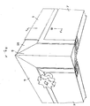
- Figure 1 shows a corner of a cube or cuboid housing, which is constructed with the aid of a plug-in system according to the invention.
- the housing frame consists of profiled bars 6, of which three profiled bars cut to size converge in each corner. These are held together by a corner piece 69, which consists of a central cube-shaped part, from which three outlets arranged at right angles to one another extend, onto which the profile rods 6 are pushed.
- the corner piece 69 is visible by breaking off the end of a profile bar made.
- the connection between the profile stems and the corner pieces can be made, for example, by gluing, screwing or riveting.
- the profile bars are pushed so far over the corner piece 69 that this disappears completely in the profile bars.
- wall elements 1 are inserted, which bear with a contact flange 22 against a contact flange 63 of the profile rods 6 and can be locked by means of a locking bolt 41 on the wall element which engages behind the contact flange 63.
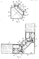
- the profile rod 6 shown in cross section in FIG. 3 consists of a first metallic profile rod part 60 and a second metallic profile rod part 70.
- the first profile rod part 60 forms a closed chamber 66 in cross section, which is delimited by two long side walls 61 adjoining one another at right angles, the other of which Each ends a short side wall 62 adjoins at right angles, the ends of which are connected to one another by a side wall 65 running obliquely to the other side walls 61, 62.
- the latter side wall 65 can also be dispensed with. From the connection points between the side walls 62 and 65, a contact flange 63 for the contact of the wall elements extends parallel to a long side wall 61.
- the second profile rod part 70 consists essentially of two known ones arranged at right angles to one another and parallel to one housing side wall Sliding grooves 71 for receiving screws 91, with the help of which devices can be fastened inside the housing.
- the screws are preferably designed as hammer head screws, which can be inserted at any point by turning into the sliding groove.
- the two profile rod parts 60 and 70 are connected to one another via two insulating web walls 65, which extend from the rear of the contact flanges 63 to the lower side of the base wall 72 of the sliding grooves extend.
- the ends of the insulating webs are dovetail-shaped.
- the relatively narrow projection 26 is initially less angled in the extruded profile rod parts and is pressed after the insertion of the insulating web walls against the insulating web walls, whereby a rigid and firm connection is achieved.
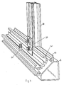
- FIG. 4 shows the connection of such an intermediate profile rod 80 to an outer profile rod 6.
- the cross-sectional profile of this intermediate profile rod can be seen in FIG. 5. It consists of two metallic intermediate profiles 81, 82, both of which are essentially plate-shaped and are connected to one another via two heat-insulating insulating web walls 65.
- the first intermediate profile rod part 81 lying on the outside of the housing forms a double contact flange 83 for two adjacent wall elements 1, of which the left one lies against the flange in FIG can be inserted from the outside, can be rotated.
- the second intermediate profile rod part 82 has a sliding groove 71 on its inward side.
- projections 26, 27 are again present for receiving the correspondingly shaped ends of the insulating web walls.
- the outermost flanges 86 of the displacement groove 71 are in the direction of Side of the intermediate profile rod extended so far that they adjoin a connected wall element.
- the intermediate profile rod is butted onto the high edges of the contact flange 63 and the displacement groove 71 and is connected to the latter with a bracket 90 and two screws via adjacent displacement grooves of the intermediate profile rod and the main profile rod.
Abstract
Description
Die Erfindung betrifft ein Stecksystem zum Aufbau eines Gehäuserahmens gemäß dem Oberbegriff des Anspruches 1. Ein 16 solches Stecksystem ist im wesentlichen bekannt aus der DE-OS 2511584.The invention relates to a plug system for constructing a housing frame according to the preamble of claim 1. A 16 such plug system is essentially known from DE-OS 2511584.
Bei dem bekannten Stecksystem sind die Profilstangen als einteilige metallische Strangpreßprofile ausgebildet, wobei die im Profilstangenquerschnitt liegenden Mittellinie a (Figur 3) der Verschiebenuten etwa unter 45 Grad zu den langen Seitewänden der Profilstange verläuft.In the known plug-in system, the profile rods are designed as one-piece metallic extruded profiles, the center line a (FIG. 3) of the sliding grooves lying in the profile rod cross section extending approximately at 45 degrees to the long side walls of the profile rod.
Ein Nachteil des bekannten Stecksystems besteht darin, daß die Profilstangen bei Verwendung wärmeisolierender Wandelemente unerwünschte Wärmebrücken zwischen dem Innenraum des Gehäuses und der Umgebung bilden. Ein weiterer Nachteil ist die genannte, zu den Seitewänden der Profilstange schräg verlaufende Anordnung der Verschiebenut, die eine Befestigung von Einbauten häufig erschwert.A disadvantage of the known plug-in system is that the profile rods form undesirable thermal bridges between the interior of the housing and the environment when using heat-insulating wall elements. Another disadvantage is the arrangement of the sliding groove which runs obliquely to the side walls of the profile rod and which often makes it more difficult to fix internals.
Der Erfindung liegt die Aufgabe zugrunde ein Stecksystem der eingangs genannten Art zu entwickeln, bei welchem ein Wärmedurchtritt durch die Profilstangen wesentlich erschwert ist und die Befestigung von Einbauteilen mit Hilfe von Schrauben in den Verschiebenuten erleichtert ist.The invention has for its object to develop a plug-in system of the type mentioned, in which the passage of heat through the profile bars is significantly more difficult and the fastening of built-in parts is facilitated by means of screws in the sliding grooves.
Zur Lösung dieser Aufgabe wird ein Stecksystem gemäß dem Oberbegriff des Anspruches 1 vorgeschlagen, welches erfindungsgemäß die im kennzeichnenden Teil des Anspruches 1 genannten Merkmale hat.To solve this problem, a plug-in system is proposed according to the preamble of claim 1, which according to the invention has the features mentioned in the characterizing part of claim 1.
Vorteilhafte Ausgestaltungen der Erfindung sind in den weiteren Ansprüchen genannt.Advantageous embodiments of the invention are mentioned in the further claims.
Anhand der in den Figuren gezeigten Ausführungsbeispiele soll die Erfindung näher erläutert werden. Es zeigen
- Figur 1 die Ecke eines Gehäuses, deren Rahmen aus einem Stecksystem gemäß der Erfindung aufgebaut ist und in welchen Wandelemente eingesetzt sind,
- Figur 2 eine Ansicht von oben auf den in Figur 1 gezeigten Gehäuseausschnitt,
- Figur 3 ein Ausführungsbeispiel einer bei dem Stecksystem nach der Erfindung verwendbaren Profilstange im Querschnitt,
- Figur 4 ein Ausführungsbeispiel einer an eine Außenprofilstange angeschlossenen Zwischenprofilstange,
- Figur 5 die Zwischenprofilstange gemäß Figur 4 im Querschnitt mit daran anschließbaren Wandelementen.
- 1 shows the corner of a housing, the frame of which is constructed from a plug-in system according to the invention and in which wall elements are used,
- FIG. 2 shows a view from above of the housing section shown in FIG. 1,
- FIG. 3 shows an exemplary embodiment in cross section of a profile rod that can be used in the plug-in system according to the invention,
- FIG. 4 shows an exemplary embodiment of an intermediate profile rod connected to an outer profile rod,
- Figure 5 shows the intermediate profile rod according to Figure 4 in cross section with attachable wall elements.
Figur 1 zeigt eine Ecke eines würfel- oder quaderförmigen Gehäuses, welches mit Hilfe eines Stecksystems gemäß der Erfindung aufgebaut ist. Der Gehäuserahmen besteht aus Profilstangen 6, von denen in jeder Ecke drei auf Gährung abgeschnittene Profilstangen zusammenlaufen. Diese werden zusammengehalten durch ein Eckstück 69, das aus einem zentralen würfelförmigen Teil besteht, von dem drei rechtwinklig zueinander angeordnete Stutzen ausgehen, auf welche die Profilstangen 6 aufgeschoben sind. In Figur 1 ist das Eckstück 69 durch Wegbrechen des Endes einer Profilstange sichtbar gemacht. Die Verbindung zwischen den Profilstanqen und den Eckstücken kann beispielsweise durch Kleben, Schrauben oder Nieten erfolgen. Die Profilstangen sind soweit über das Eckstück 69 geschoben, daß dieses vollständig in den Profilstangen verschwindet. In die von den Profilstangen 6 gebildeten Seitenöffnungen sind Wandelemente 1 eingesetzt, die mit einem Anlageflansch 22 gegen einen Anlageflansch 63 der Profilstangen 6 anliegen und mittels eines am Wandelement vorhandenen Verschlußriegel 41, der hinter den Anlageflansch 63 greift, verriegelbar sind.Figure 1 shows a corner of a cube or cuboid housing, which is constructed with the aid of a plug-in system according to the invention. The housing frame consists of profiled
Die in Figur 3 im Querschnitt gezeigte Profilstange 6 besteht aus einem ersten metallischen Profilstangenteil 60 und einem zweiten metallischen Profilstangenteil 70. Das erste Profilstangenteil 60 bildet im Querschnitt eine geschlossene Kammer 66, die begrenzt wird von zwei rechwinklig aneinander grenzenden langen Seitewänden 61, an deren anderen Enden sich je eine kurze Seitewand 62 rechtwinklig anschließt, deren Enden durch eine schräg zu den anderen Seitewänden 61,62 verlaufende Seitewand 65 miteinander verbunden sind. Auf die letztgenannte Seitewand 65 kann auch verzichtet werden. Von den Verbindungspunkten zwischen den Seitewänden 62 und 65 erstreckt sich je ein Anlageflansch 63 für die Anlage der Wandelemente parallel zu je einer langen Seitewand 61. Das zweite Profilstangenteil 70 besteht im wesentlichen aus zwei rechtwinklig zueinander und parallel zu je einer Gehäuseseitenwand angeordnete, an sich bekannte Verschiebenuten 71 zur Aufnahme von Schrauben 91, mit deren Hilfe Geräte im Inneren des Gehäuses befestigt werden können. Die Schrauben sind vorzugsweise als Hammerkopfschrauben ausgebildet, die an jeder beliebigen Stelle durch Drehen in die Verschiebenut einsetzbar sind. Zur Verhinderung eines Wärmedurchtrittes durch die Profilstange vom Gehäuseinneren nach außen oder umgekehrt sind die beiden Profilstangenteile 60 und 70 über zwei Isolierstegwände 65 miteinander verbunden, die sich von der Rückseite der Anlageflansche 63 zur unteren Seite der Boden wand 72 der Verschiebenuten erstrecken. Die Isolierstegwände sind an ihren Enden schwalbenschwanzförmig ausgebildet. Eine andere Möglichkeit ihrer Ausbildung besteht darin, sie an ihren Enden abzuwinkeln, wie dies bei den Isolierstegwänden 65 in Figur 5 der Fall ist. Der relativ schmale Vorsprung 26 ist bei den stranggepreßten Profilstangenteilen zunächst weniger stark abgewinkelt und wird nach dem Einsetzen der Isolierstegwände gegen die Isolierstegwände gedrückt, wodurch eine starre und feste Verbindung erreicht wird.The
Zwischen den Außenprofilstange 6, die in derselben Seitenebene des Gehäuses liegen, können Zwischenprofilstangen 80 eingefügt werden (Figur 4 und 5), wodurch die Seitenöffnung des Gehäuserahmens in zwei oder mehrere Felder unterteilt werden kann. In jedes dieser Felder ist dann ein Wandelement einsetzbar. Figur 4 zeigt den Anschluß einer solchen Zwischenprofilstange 80 an eine Außenprofilstange 6. Das Querschnittsprofil dieser Zwischenprofilstange ist aus Figur 5 ersichtlich. Es besteht aus zwei metallischen Zwischenprofilen 81,82, die beide im wesentlichen plattenförmig ausgebildet sind und über zwei wärmeisolierende Isolierstegwände 65 miteinander verbunden sind. Das zur Außenseite des Gehäuses liegende erste Zwischenprofilstangenteil 81 bildet einen Doppelanlageflansch 83 für zwei benachbarte Wandelemente 1, von denen in Figur 5 das linke am Flansch anliegt und mit diesem über einen drehbaren Verschlußriegel 41 verriegelt ist, der über eine Antriebswelle 42, in die ein Vierkantschlüssel von außen einsteckbar ist, gedreht werden kann. Das zweite Zwischenprofilstangenteil 82 trägt auf seiner nach innen gerichteten Seite eine Verschiebenut 71. An den durch die Isolierstegwände verbundenen Seiten der beiden plattenförmigen Teile 81,82 sind wieder Vorsprünge 26,27 zur Aufnahme der entsprechend geformte Enden der Isolierstegwände vorhanden. Um auf der Innenseite des Gehäuses möglichst durchgehende glatte Flächen zu bekommen, sind die äußersten Flansche 86 der Verschiebenut 71 in Richtung zur Seite der Zwischenprofilstange soweit verlängert, daß sie an ein angeschlossenes Wandelement angrenzen.
Wie Figur 4 zeigt, wird die Zwischenprofilstange stumpf auf die hohen Kanten des Anlageflansches 63 und der Verschiebenut 71 aufgesetzt und mit einer Lasche 90 und zwei Schrauben über benachbarte Verschiebenuten von Zwischenprofilstange und Hauptprofilstange mit der letzteren verbunden.As FIG. 4 shows, the intermediate profile rod is butted onto the high edges of the
Claims (8)
Priority Applications (1)
| Application Number | Priority Date | Filing Date | Title |
|---|---|---|---|
| AT88103469T ATE91858T1 (en) | 1987-03-12 | 1988-03-05 | PLUG-IN SYSTEM FOR CONSTRUCTING A HOUSING FRAME. |
Applications Claiming Priority (2)
| Application Number | Priority Date | Filing Date | Title |
|---|---|---|---|
| DE8703695U DE8703695U1 (en) | 1987-03-12 | 1987-03-12 | |
| DE8703695U | 1987-03-12 |
Publications (3)
| Publication Number | Publication Date |
|---|---|
| EP0281983A2 true EP0281983A2 (en) | 1988-09-14 |
| EP0281983A3 EP0281983A3 (en) | 1989-05-03 |
| EP0281983B1 EP0281983B1 (en) | 1993-07-28 |
Family
ID=6805739
Family Applications (1)
| Application Number | Title | Priority Date | Filing Date |
|---|---|---|---|
| EP88103469A Expired - Lifetime EP0281983B1 (en) | 1987-03-12 | 1988-03-05 | Assembling system for a housing frame |
Country Status (3)
| Country | Link |
|---|---|
| EP (1) | EP0281983B1 (en) |
| AT (1) | ATE91858T1 (en) |
| DE (2) | DE8703695U1 (en) |
Cited By (7)
| Publication number | Priority date | Publication date | Assignee | Title |
|---|---|---|---|---|
| FR2648005A1 (en) * | 1989-06-05 | 1990-12-07 | Merlin Gerin | WATERPROOF CABINET OF ELECTRICAL EQUIPMENT |
| FR2675961A1 (en) * | 1991-04-29 | 1992-10-30 | Merlin Gerin | EXTENSION FOR ELECTRICAL BOX. |
| FR2682257A1 (en) * | 1991-10-02 | 1993-04-09 | Loh Rittal Werk Gmbh Co | HOLLOW PROFILE FOR A CHASSIS-FRAME OF A SWITCHING CABINET. |
| WO1995011538A1 (en) * | 1993-10-23 | 1995-04-27 | Rittal-Werk Rudolf Loh Gmbh & Co. Kg | Switch cupboard with a rack made of frame pieces |
| WO2001040599A1 (en) * | 1999-11-30 | 2001-06-07 | Ul Tech Ag | Frame structural system |
| GB2529827A (en) * | 2014-09-02 | 2016-03-09 | Cp Cases Ltd | Electronic rack and mounting chassis |
| CN108899779A (en) * | 2018-08-27 | 2018-11-27 | 江苏南瑞帕威尔电气有限公司 | A kind of reinforced type switch cabinet back door and reinforced type switch cabinet |
Families Citing this family (12)
| Publication number | Priority date | Publication date | Assignee | Title |
|---|---|---|---|---|
| DE9203100U1 (en) * | 1992-03-09 | 1993-07-08 | Boewe Systec Ag | |
| DE4227532C3 (en) * | 1992-08-20 | 1999-01-14 | Thielmann Ag Kg | Frame profile for the frame of a control cabinet |
| DE9217801U1 (en) * | 1992-12-23 | 1993-02-25 | Hansa Ventilatoren U. Maschinenbau Neumann Gmbh & Co Kg, 2915 Saterland, De | |
| DE4336187C2 (en) * | 1993-10-23 | 1996-12-12 | Loh Kg Rittal Werk | Frame leg for a frame of a control cabinet |
| DE4336204C2 (en) * | 1993-10-23 | 1996-11-07 | Loh Kg Rittal Werk | Frame for a control cabinet |
| DE4439551C1 (en) * | 1994-11-05 | 1995-12-21 | Loh Kg Rittal Werk | Frame post for switchgear cabinet |
| DE19507438C1 (en) * | 1995-03-03 | 1996-04-04 | Loh Kg Rittal Werk | Mounting rail fixing for switch cabinet frame |
| DE19537016C1 (en) * | 1995-10-04 | 1996-10-10 | Loh Kg Rittal Werk | Switching cabinet mounting frame |
| DE19536950C1 (en) * | 1995-10-04 | 1996-11-21 | Loh Kg Rittal Werk | Shaped frame struts for construction of switch-cabinet housing |
| DE29521934U1 (en) * | 1995-10-04 | 1998-09-24 | Loh Kg Rittal Werk | Frame leg for a control cabinet |
| DE19544432C2 (en) * | 1995-11-29 | 1999-07-29 | Loh Kg Rittal Werk | Frame for a control cabinet |
| DE202018100613U1 (en) * | 2018-02-05 | 2018-02-14 | Rittal Gmbh & Co. Kg | Arrangement with two interconnected via a bay connector control cabinet frame racks |
Citations (4)
| Publication number | Priority date | Publication date | Assignee | Title |
|---|---|---|---|---|
| DE2731328A1 (en) * | 1977-07-12 | 1979-02-01 | Guenter Smitka | Housing for electrical and electronic equipment - has frame elements with fastening members for direct attachment of mounting bars |
| GB2083116A (en) * | 1980-09-03 | 1982-03-17 | Gartner & Co J | Composite bar |
| DE3120076A1 (en) * | 1981-05-20 | 1982-12-09 | Helmar Dr.Dr. 8530 Neustadt Nahr | Heat-insulating profile body |
| CH662166A5 (en) * | 1984-03-23 | 1987-09-15 | Semilavorati Spa | Metallic anticondensation section, in particular for refrigerated conditioning and display cabinet |
-
1987
- 1987-03-12 DE DE8703695U patent/DE8703695U1/de not_active Expired
-
1988
- 1988-03-05 DE DE8888103469T patent/DE3882555D1/en not_active Expired - Fee Related
- 1988-03-05 EP EP88103469A patent/EP0281983B1/en not_active Expired - Lifetime
- 1988-03-05 AT AT88103469T patent/ATE91858T1/en not_active IP Right Cessation
Patent Citations (4)
| Publication number | Priority date | Publication date | Assignee | Title |
|---|---|---|---|---|
| DE2731328A1 (en) * | 1977-07-12 | 1979-02-01 | Guenter Smitka | Housing for electrical and electronic equipment - has frame elements with fastening members for direct attachment of mounting bars |
| GB2083116A (en) * | 1980-09-03 | 1982-03-17 | Gartner & Co J | Composite bar |
| DE3120076A1 (en) * | 1981-05-20 | 1982-12-09 | Helmar Dr.Dr. 8530 Neustadt Nahr | Heat-insulating profile body |
| CH662166A5 (en) * | 1984-03-23 | 1987-09-15 | Semilavorati Spa | Metallic anticondensation section, in particular for refrigerated conditioning and display cabinet |
Cited By (14)
| Publication number | Priority date | Publication date | Assignee | Title |
|---|---|---|---|---|
| US5202818A (en) * | 1989-06-05 | 1993-04-13 | Merlin Gerin | Sealed switchgear cabinet |
| EP0402276A1 (en) * | 1989-06-05 | 1990-12-12 | Merlin Gerin | Sealed cabinet for electrical apparatus |
| TR24645A (en) * | 1989-06-05 | 1992-01-01 | Merlin Gerin | SEALING BOARD OF SEALING. |
| AU624717B2 (en) * | 1989-06-05 | 1992-06-18 | Schneider Electric Sa | Sealed switchgear cabinet |
| FR2648005A1 (en) * | 1989-06-05 | 1990-12-07 | Merlin Gerin | WATERPROOF CABINET OF ELECTRICAL EQUIPMENT |
| FR2675961A1 (en) * | 1991-04-29 | 1992-10-30 | Merlin Gerin | EXTENSION FOR ELECTRICAL BOX. |
| EP0512929A1 (en) * | 1991-04-29 | 1992-11-11 | Schneider Electric Sa | Base frame for electrical box |
| FR2682257A1 (en) * | 1991-10-02 | 1993-04-09 | Loh Rittal Werk Gmbh Co | HOLLOW PROFILE FOR A CHASSIS-FRAME OF A SWITCHING CABINET. |
| WO1995011538A1 (en) * | 1993-10-23 | 1995-04-27 | Rittal-Werk Rudolf Loh Gmbh & Co. Kg | Switch cupboard with a rack made of frame pieces |
| WO2001040599A1 (en) * | 1999-11-30 | 2001-06-07 | Ul Tech Ag | Frame structural system |
| GB2529827A (en) * | 2014-09-02 | 2016-03-09 | Cp Cases Ltd | Electronic rack and mounting chassis |
| GB2529827B (en) * | 2014-09-02 | 2017-01-04 | Cp Cases Ltd | Electronic rack and mounting chassis |
| US10045460B2 (en) | 2014-09-02 | 2018-08-07 | Cp Cases Limited | Electronic rack and mounting chassis |
| CN108899779A (en) * | 2018-08-27 | 2018-11-27 | 江苏南瑞帕威尔电气有限公司 | A kind of reinforced type switch cabinet back door and reinforced type switch cabinet |
Also Published As
| Publication number | Publication date |
|---|---|
| DE3882555D1 (en) | 1993-09-02 |
| EP0281983B1 (en) | 1993-07-28 |
| DE8703695U1 (en) | 1987-12-17 |
| ATE91858T1 (en) | 1993-08-15 |
| EP0281983A3 (en) | 1989-05-03 |
Similar Documents
| Publication | Publication Date | Title |
|---|---|---|
| EP0281983A2 (en) | Assembling system for a housing frame | |
| EP0404284B1 (en) | Framework for a switchbox consisting of a multiple of profiled elements, the said elements having a plurality of bends | |
| DE3843911C2 (en) | ||
| DE2152341C3 (en) | Construction toys | |
| EP0384153A2 (en) | Supporting chain for energy carrier | |
| EP1994614B1 (en) | Frame construction for a switchgear cabinet, switchgear cabinet and construction kit for the switchgear cabinet | |
| WO2006092391A1 (en) | Profile connector | |
| DE3441416A1 (en) | Electrical plug connector | |
| EP0032408A2 (en) | Thermally insulating profile member | |
| DE3442550C1 (en) | Connection shoe for C-shaped sheet-metal profiles | |
| EP0182288B1 (en) | Cubical construction | |
| EP0039467A2 (en) | Spacer | |
| DE2803972C2 (en) | Meter and distributor cabinet made from plastic extruder profiles | |
| DE202006020037U1 (en) | Frame construction for a control cabinet, control cabinet and kit for the control cabinet | |
| CH683807A5 (en) | Apparatus for recording LPs, tape or video cassettes. | |
| EP0623530A1 (en) | Overhead conveyor system with a set of profiling strips for mounting | |
| EP0067970A1 (en) | Fastening device for facing elements on outer wall | |
| DE3706236C2 (en) | Connection element for two supporting parts | |
| DE3001445A1 (en) | HOLLOW BARS BUILT WITH BOARDS | |
| EP0959536B1 (en) | Multisocket power outlet box | |
| DE841499C (en) | Component in the form of a U-rail | |
| DE19824063A1 (en) | I-shaped beam for building constructions | |
| DE3610377C2 (en) | ||
| DE4227531C2 (en) | Corner connector for a frame of a control cabinet | |
| DE8109470U1 (en) | "Schematic pocket for a control cabinet" |
Legal Events
| Date | Code | Title | Description |
|---|---|---|---|
| PUAI | Public reference made under article 153(3) epc to a published international application that has entered the european phase |
Free format text: ORIGINAL CODE: 0009012 |
|
| AK | Designated contracting states |
Kind code of ref document: A2 Designated state(s): AT BE CH DE FR GB IT LI NL SE |
|
| PUAL | Search report despatched |
Free format text: ORIGINAL CODE: 0009013 |
|
| RHK1 | Main classification (correction) |
Ipc: A47B 47/03 |
|
| AK | Designated contracting states |
Kind code of ref document: A3 Designated state(s): AT BE CH DE FR GB IT LI NL SE |
|
| 17P | Request for examination filed |
Effective date: 19891021 |
|
| 17Q | First examination report despatched |
Effective date: 19910926 |
|
| GRAA | (expected) grant |
Free format text: ORIGINAL CODE: 0009210 |
|
| AK | Designated contracting states |
Kind code of ref document: B1 Designated state(s): AT BE CH DE FR GB IT LI NL SE |
|
| REF | Corresponds to: |
Ref document number: 91858 Country of ref document: AT Date of ref document: 19930815 Kind code of ref document: T |
|
| REF | Corresponds to: |
Ref document number: 3882555 Country of ref document: DE Date of ref document: 19930902 |
|
| ET | Fr: translation filed | ||
| ITF | It: translation for a ep patent filed |
Owner name: JACOBACCI CASETTA & PERANI S.P.A. |
|
| GBT | Gb: translation of ep patent filed (gb section 77(6)(a)/1977) |
Effective date: 19931027 |
|
| PGFP | Annual fee paid to national office [announced via postgrant information from national office to epo] |
Ref country code: GB Payment date: 19940303 Year of fee payment: 7 |
|
| PGFP | Annual fee paid to national office [announced via postgrant information from national office to epo] |
Ref country code: FR Payment date: 19940310 Year of fee payment: 7 |
|
| PGFP | Annual fee paid to national office [announced via postgrant information from national office to epo] |
Ref country code: BE Payment date: 19940315 Year of fee payment: 7 |
|
| PGFP | Annual fee paid to national office [announced via postgrant information from national office to epo] |
Ref country code: SE Payment date: 19940324 Year of fee payment: 7 |
|
| PGFP | Annual fee paid to national office [announced via postgrant information from national office to epo] |
Ref country code: CH Payment date: 19940328 Year of fee payment: 7 |
|
| PGFP | Annual fee paid to national office [announced via postgrant information from national office to epo] |
Ref country code: AT Payment date: 19940329 Year of fee payment: 7 |
|
| PGFP | Annual fee paid to national office [announced via postgrant information from national office to epo] |
Ref country code: NL Payment date: 19940331 Year of fee payment: 7 |
|
| PLBE | No opposition filed within time limit |
Free format text: ORIGINAL CODE: 0009261 |
|
| STAA | Information on the status of an ep patent application or granted ep patent |
Free format text: STATUS: NO OPPOSITION FILED WITHIN TIME LIMIT |
|
| 26N | No opposition filed | ||
| EAL | Se: european patent in force in sweden |
Ref document number: 88103469.8 |
|
| PG25 | Lapsed in a contracting state [announced via postgrant information from national office to epo] |
Ref country code: GB Effective date: 19950305 Ref country code: AT Effective date: 19950305 |
|
| PG25 | Lapsed in a contracting state [announced via postgrant information from national office to epo] |
Ref country code: SE Effective date: 19950306 |
|
| PG25 | Lapsed in a contracting state [announced via postgrant information from national office to epo] |
Ref country code: LI Effective date: 19950331 Ref country code: CH Effective date: 19950331 Ref country code: BE Effective date: 19950331 |
|
| BERE | Be: lapsed |
Owner name: FISCHBACH G.M.B.H. & CO. K.G. Effective date: 19950331 |
|
| PG25 | Lapsed in a contracting state [announced via postgrant information from national office to epo] |
Ref country code: NL Effective date: 19951001 |
|
| GBPC | Gb: european patent ceased through non-payment of renewal fee |
Effective date: 19950305 |
|
| PG25 | Lapsed in a contracting state [announced via postgrant information from national office to epo] |
Ref country code: FR Free format text: LAPSE BECAUSE OF NON-PAYMENT OF DUE FEES Effective date: 19951130 |
|
| REG | Reference to a national code |
Ref country code: CH Ref legal event code: PL |
|
| NLV4 | Nl: lapsed or anulled due to non-payment of the annual fee |
Effective date: 19951001 |
|
| EUG | Se: european patent has lapsed |
Ref document number: 88103469.8 |
|
| REG | Reference to a national code |
Ref country code: FR Ref legal event code: ST |
|
| PGFP | Annual fee paid to national office [announced via postgrant information from national office to epo] |
Ref country code: DE Payment date: 19960529 Year of fee payment: 9 |
|
| PG25 | Lapsed in a contracting state [announced via postgrant information from national office to epo] |
Ref country code: DE Effective date: 19971202 |
|
| PG25 | Lapsed in a contracting state [announced via postgrant information from national office to epo] |
Ref country code: IT Free format text: LAPSE BECAUSE OF NON-PAYMENT OF DUE FEES Effective date: 20050305 |