EP0442456A1 - Spanndorn - Google Patents
Spanndorn Download PDFInfo
- Publication number
- EP0442456A1 EP0442456A1 EP91101983A EP91101983A EP0442456A1 EP 0442456 A1 EP0442456 A1 EP 0442456A1 EP 91101983 A EP91101983 A EP 91101983A EP 91101983 A EP91101983 A EP 91101983A EP 0442456 A1 EP0442456 A1 EP 0442456A1
- Authority
- EP
- European Patent Office
- Prior art keywords
- clamping
- bodies
- clamping head
- head
- clamping bodies
- Prior art date
- Legal status (The legal status is an assumption and is not a legal conclusion. Google has not performed a legal analysis and makes no representation as to the accuracy of the status listed.)
- Withdrawn
Links
Images

Classifications
-
- B—PERFORMING OPERATIONS; TRANSPORTING
- B23—MACHINE TOOLS; METAL-WORKING NOT OTHERWISE PROVIDED FOR
- B23B—TURNING; BORING
- B23B31/00—Chucks; Expansion mandrels; Adaptations thereof for remote control
- B23B31/40—Expansion mandrels
- B23B31/404—Gripping the work or tool by jaws moving radially controlled by conical surfaces
- B23B31/4066—Gripping the work or tool by jaws moving radially controlled by conical surfaces using mechanical transmission through the spindle
-
- Y—GENERAL TAGGING OF NEW TECHNOLOGICAL DEVELOPMENTS; GENERAL TAGGING OF CROSS-SECTIONAL TECHNOLOGIES SPANNING OVER SEVERAL SECTIONS OF THE IPC; TECHNICAL SUBJECTS COVERED BY FORMER USPC CROSS-REFERENCE ART COLLECTIONS [XRACs] AND DIGESTS
- Y10—TECHNICAL SUBJECTS COVERED BY FORMER USPC
- Y10S—TECHNICAL SUBJECTS COVERED BY FORMER USPC CROSS-REFERENCE ART COLLECTIONS [XRACs] AND DIGESTS
- Y10S279/00—Chucks or sockets
- Y10S279/901—Chuck or chuck jaw changing means
-
- Y—GENERAL TAGGING OF NEW TECHNOLOGICAL DEVELOPMENTS; GENERAL TAGGING OF CROSS-SECTIONAL TECHNOLOGIES SPANNING OVER SEVERAL SECTIONS OF THE IPC; TECHNICAL SUBJECTS COVERED BY FORMER USPC CROSS-REFERENCE ART COLLECTIONS [XRACs] AND DIGESTS
- Y10—TECHNICAL SUBJECTS COVERED BY FORMER USPC
- Y10T—TECHNICAL SUBJECTS COVERED BY FORMER US CLASSIFICATION
- Y10T279/00—Chucks or sockets
- Y10T279/10—Expanding
- Y10T279/1004—Collet type
- Y10T279/1012—Fixed cam and moving jaws
-
- Y—GENERAL TAGGING OF NEW TECHNOLOGICAL DEVELOPMENTS; GENERAL TAGGING OF CROSS-SECTIONAL TECHNOLOGIES SPANNING OVER SEVERAL SECTIONS OF THE IPC; TECHNICAL SUBJECTS COVERED BY FORMER USPC CROSS-REFERENCE ART COLLECTIONS [XRACs] AND DIGESTS
- Y10—TECHNICAL SUBJECTS COVERED BY FORMER USPC
- Y10T—TECHNICAL SUBJECTS COVERED BY FORMER US CLASSIFICATION
- Y10T82/00—Turning
- Y10T82/26—Work driver
- Y10T82/266—Mandrel
- Y10T82/268—Expansible
Definitions
- the invention relates to a mandrel for machine tools with a plurality of radially aligned clamping bodies, each of which is provided with a flat surface and is supported with this surface on an associated support surface of a cross-section polygonal clamping cone, against which the clamping body for generating a radial clamping movement in the axial direction Direction are displaceable by a tensile body, the clamping bodies are each formed with a radially oriented projection for positive entrainment during the axial movement.
- Mandrels of the type mentioned at the beginning are used for clamping workpieces or tools during machining. Often, they not only support the machining forces, but also automatically bring the workpiece or tool into a specific position required for perfect machining during the clamping process.
- a mandrel can always be used for different shapes and dimensions of workpieces or tools within a certain range. Workpieces are clamped in their pre-machined or finished bores on mandrels during turning and external cylindrical grinding. The clamping force acts radially from the inside out.
- the mandrel has several clamping bodies that are evenly distributed over the circumference and are radially adjustable. The known mandrels have a relatively low concentricity.
- the invention has for its object to develop a generic mandrel so that a concentricity can be maintained with an accuracy of less than 10 ⁇ 2 mm.
- clamping bodies are arranged in radial, open to the front receptacles of a clamping head, which is provided with an annular groove for receiving the projections of the clamping body and can be connected to the traction body by a quickly releasable connection (bayonet lock), and that the clamping head is held in its position of use by an unlockable anti-rotation lock against rotation.
- the mandrel according to the invention thus consists of a clamping head with radially aligned slots, the mutually facing inner walls of which run parallel to one another and are matched to the thickness of the clamping bodies.
- the clamping bodies can move radially inwards or outwards. Since the surfaces are flat and lie in one plane with the support surfaces, it is ensured that the surfaces facing one another are in pressure connection with one another over maximum surfaces. The wear of the surfaces and the support surfaces is therefore minimal. All forces acting on the clamping body are therefore radially aligned.
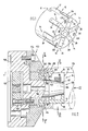
- the mandrel 10 shown in the figures comprises a clamping head 12 which has radially aligned clamping bodies 14 with surfaces 64 (cf. FIG. 6) and which cooperate with a clamping cone 104 having clamping cones 104.
- the support surfaces 62 are designed as flat sections of the tensioning cone 104 tapering towards its free end, which lie in one plane with the associated surfaces 64.
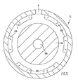
- the lamellar clamping bodies 14 have an approximately rectangular cross-section with outer sides 26 and end faces 38.
- the outer sides 26 of the clamping bodies 14 are in pressure connection with a workpiece 126, while the end sides 38 protrude from the mandrel 10 on the one hand and face the interior of the workpiece 126 on the other hand are.
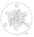
- the lamellar clamping bodies 14 are mounted in receptacles 92 arranged radially in the clamping head 12.
- the recordings 92 have extensions, which as annular recess in the clamping head 12 are formed. In these extensions, elastically deformable holding bodies 80 made of rubber or plastic, which connect the clamping bodies 14 to the clamping head 12, are used, so that the holding bodies 80 endeavor to move the clamping bodies 14 radially inwards.
- the coupling elements are designed on the one hand as projections 142 arranged radially on the clamping bodies 14 and on the other hand as grooves 140 made in the clamping head 12.
- the projections 142 of the clamping bodies 14 engage in the corresponding grooves 140 of the clamping head 12.
- the grooves 140 are open radially inwards and result in an annular groove in which the projections 142 of the clamping bodies 14 are suspended.
- the clamping bodies 14 are clamped in the clamping head 12 by the holding bodies 80 arranged between the individual clamping bodies 14. In order not to adversely affect the accuracy of the setting by hooking the projections 142 into the grooves 140, the radial depth of the grooves 140 is matched to the working area of the clamping bodies 14.
- the clamping head 12 furthermore has a radial groove 144, which is formed by radial projections 200 and 202 at the end facing away from the workpiece 126.
- Corresponding projections 204 arranged on the pull body 156 engage in this groove 144 and, together with the projections 202, form a bayonet lock, which can be released when the mandrel 10 is rotated relative to the pull body 156.
- the projections 204 of the tension member 156 enter recesses arranged between the projections 202, so that the mandrel 10 can be pulled off the clamping cone 104.
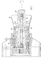
- an unlocking device 160 is provided, with which the force to move the clamping body 14 held by the holding bodies 80 can be generated (see FIG. 3).
- An axial bore 106 is formed in the clamping cone 104, to which a recess 175 extending in the radial direction of the clamping cone 104 is connected.
- An actuating mechanism is arranged in the bore 106 and the recess 175, which has an actuating bolt 172 arranged in the bore 106, which is connected in a rotationally fixed manner to a yoke 174 arranged in the recess 175.
- a locking pin 176 arranged parallel to the actuating pin 172 is fastened to the yoke 174 and, when the mandrel 10 is placed on the clamping cone 104, engages in a locking receptacle 8 which is arranged on the end of the clamping head 12 facing away from the workpiece 126.
- the locking pin 176 secures the mandrel 10 in its working position.
- the bore 106 is widened; a spring 170 is arranged in the widening, which actuating bolt 172 with yoke 174 arranged thereon and the locking pin 176 in the direction of the conical end of the clamping cone.
- the actuating pin 172 is movable on a working stroke h2 in the axial direction of the mandrel. This stroke h2 is larger than an unlocking stroke h1, through which the locking pin 176 can be pulled out of the locking receptacle 8. Accordingly, the working stroke h2 is greater than the depth of the locking receptacle 8.
- the unlocking device 160 has an axially extending unlocking bolt 162 which engages in the bore 106 and through which the actuating bolt 172 can be displaced in the tensioning cone 104 against the force of the spring 170.
- the unlocking bolt 162 is mounted in the unlocking device 160 by means of a compression spring 164.
- driving bolts 166 are arranged on the unlocking device 160, which can be inserted into corresponding bores 120 arranged in the end face of the mandrel 10. These drive pins 166 are used for precise positioning of the unlocking device 160 on the mandrel 10.
- magnets 182 are used in addition to the drive pins 166, which hold the unlocking device 160 releasably on the mandrel 10 as adhesive bodies.
- a spindle head 152 holding the clamping cone 104 and the attached mandrel 10 is connected by means of screws 154 to a base body 158 which is fastened to the spindle of a lathe. Bores for screws 150 are provided in the base body 158, through which the pulling body 156 is connected to the bayonet catch.
- the tension body 156 is movable in the axial direction of the tensioning cone 104, the stroke d 1 of the tension body 156 being dimensioned such that the tensioning body 14 can be maximally retracted and extended according to their size.
Landscapes
- Engineering & Computer Science (AREA)
- Mechanical Engineering (AREA)
- Gripping On Spindles (AREA)
Applications Claiming Priority (2)
| Application Number | Priority Date | Filing Date | Title |
|---|---|---|---|
| DE4004819A DE4004819C1 (it) | 1990-02-16 | 1990-02-16 | |
| DE4004819 | 1990-02-16 |
Publications (1)
| Publication Number | Publication Date |
|---|---|
| EP0442456A1 true EP0442456A1 (de) | 1991-08-21 |
Family
ID=6400284
Family Applications (1)
| Application Number | Title | Priority Date | Filing Date |
|---|---|---|---|
| EP91101983A Withdrawn EP0442456A1 (de) | 1990-02-16 | 1991-02-13 | Spanndorn |
Country Status (3)
| Country | Link |
|---|---|
| US (1) | US5133565A (it) |
| EP (1) | EP0442456A1 (it) |
| DE (1) | DE4004819C1 (it) |
Cited By (3)
| Publication number | Priority date | Publication date | Assignee | Title |
|---|---|---|---|---|
| EP1884303A1 (de) | 2006-07-31 | 2008-02-06 | Gebr. Heller Maschinenfabrik GmbH | Verfahren zum Zentrieren von Werkstücken sowie Vorrichtung zur Durchführung eines solchen Verfahrens |
| CN103182402A (zh) * | 2011-12-29 | 2013-07-03 | 安东石油技术(集团)有限公司 | 一种涨紧机构及其制造方法及炮管 |
| CN107350496A (zh) * | 2017-09-04 | 2017-11-17 | 福建兵工装备有限公司 | 加工套筒类零件外圆的专用夹具 |
Families Citing this family (15)
| Publication number | Priority date | Publication date | Assignee | Title |
|---|---|---|---|---|
| DE19526348C1 (de) * | 1995-07-19 | 1997-02-06 | Preh Elektro Feinmechanik | Verfahren und Vorrichtung zur Anpressung von geklebten Folienstreifen |
| DE19543178A1 (de) * | 1995-11-20 | 1997-05-22 | Weh Verbindungstechnik | Spannzangenvorrichtung |
| US5816581A (en) * | 1997-02-20 | 1998-10-06 | Chase; R. Lee | ID chuck providing workpiece registration and operable by push or pull to attach a workpiece |
| US6279437B1 (en) | 1998-05-26 | 2001-08-28 | Climax Portable Machine Tools, Inc. | Pipe beveling machine |
| US6536316B2 (en) * | 1999-11-29 | 2003-03-25 | Climax Portable Machine Tools, Inc. | Pipe beveling and facing tool |
| US6883407B2 (en) * | 2002-08-30 | 2005-04-26 | Hardinge Inc. | Expanding collet assembly for pick-off spindle |
| US6980874B2 (en) * | 2003-07-01 | 2005-12-27 | General Electric Company | System and method for detecting an anomalous condition in a multi-step process |
| DE20320084U1 (de) * | 2003-12-23 | 2004-03-04 | Hainbuch Gmbh Spannende Technik | Innenspanneinrichtung und damit ausgerüstetes Spannsystem |
| US8684364B2 (en) * | 2007-01-12 | 2014-04-01 | Sil Han | Positive release collet |
| ITBS20110131A1 (it) * | 2011-09-28 | 2013-03-29 | Gnutti Transfer S P A | Macchina utensile con dispositivo di supporto ed afferraggio di pezzi meccanici |
| CN103286323B (zh) * | 2013-05-02 | 2015-06-24 | 中冶陕压重工设备有限公司 | 利用涨胎式芯轴加工长薄壁套的方法 |
| CA2843304A1 (en) * | 2013-07-22 | 2015-01-22 | Narr Beteiligungs Gmbh | Clamping device |
| DE102016005373A1 (de) * | 2016-04-26 | 2017-10-26 | Westinghouse Electric Germany Gmbh | Spannvorrichtung |
| DE102016116666A1 (de) | 2016-09-06 | 2018-03-08 | GDS Präzisionszerspanungs GmbH | Werkzeugmaschinenvorrichtung |
| CN110944782B (zh) * | 2017-05-26 | 2021-11-02 | 莱维克龙有限公司 | 自锁空心转轴夹紧机构 |
Citations (2)
| Publication number | Priority date | Publication date | Assignee | Title |
|---|---|---|---|---|
| FR2212201A1 (it) * | 1973-01-03 | 1974-07-26 | Tobler Sa | |
| DE9001831U1 (de) * | 1990-02-16 | 1990-04-19 | Schmidt, Claus, 7120 Bietigheim-Bissingen | Spanndorn mit Spannkopf |
Family Cites Families (14)
| Publication number | Priority date | Publication date | Assignee | Title |
|---|---|---|---|---|
| US1808288A (en) * | 1925-04-24 | 1931-06-02 | Gen Motors Corp | Work holder |
| US1807264A (en) * | 1929-02-27 | 1931-05-26 | Titan Tool Co | Self-opening tool |
| US2270661A (en) * | 1939-01-12 | 1942-01-20 | New Britain Machine Co | Spring collet |
| US2459899A (en) * | 1944-02-04 | 1949-01-25 | Jacobs Mfg Co | Collet |
| US2817532A (en) * | 1955-10-20 | 1957-12-24 | Woodworth Co N A | Expansion arbor with inclined flats |
| US3332693A (en) * | 1964-07-10 | 1967-07-25 | Armstrong | Collet and holder |
| FR1595583A (it) * | 1968-09-12 | 1970-06-15 | ||
| US3909021A (en) * | 1974-01-14 | 1975-09-30 | Mp Tool & Engineering Co | Collet chuck |
| CA1031940A (en) * | 1975-03-26 | 1978-05-30 | Howard A. Petteys | Expander tool |
| DE2831140A1 (de) * | 1978-07-15 | 1980-01-24 | Hainbuch Wilh Gmbh Co | Spannzange |
| US4121847A (en) * | 1977-10-28 | 1978-10-24 | Morawski London T | Collet chuck |
| US4391451A (en) * | 1980-09-17 | 1983-07-05 | Great Lakes Industries, Inc. | Expansible chuck assembly |
| US4416459A (en) * | 1981-06-03 | 1983-11-22 | Morawski Longine V | Collet chuck for splined workpieces |
| DE3629722A1 (de) * | 1986-09-01 | 1988-03-03 | Hainbuch Wilh Gmbh Co | Spannfutter |
-
1990
- 1990-02-16 DE DE4004819A patent/DE4004819C1/de not_active Expired - Lifetime
-
1991
- 1991-02-13 EP EP91101983A patent/EP0442456A1/de not_active Withdrawn
- 1991-02-15 US US07/656,300 patent/US5133565A/en not_active Expired - Fee Related
Patent Citations (2)
| Publication number | Priority date | Publication date | Assignee | Title |
|---|---|---|---|---|
| FR2212201A1 (it) * | 1973-01-03 | 1974-07-26 | Tobler Sa | |
| DE9001831U1 (de) * | 1990-02-16 | 1990-04-19 | Schmidt, Claus, 7120 Bietigheim-Bissingen | Spanndorn mit Spannkopf |
Cited By (3)
| Publication number | Priority date | Publication date | Assignee | Title |
|---|---|---|---|---|
| EP1884303A1 (de) | 2006-07-31 | 2008-02-06 | Gebr. Heller Maschinenfabrik GmbH | Verfahren zum Zentrieren von Werkstücken sowie Vorrichtung zur Durchführung eines solchen Verfahrens |
| CN103182402A (zh) * | 2011-12-29 | 2013-07-03 | 安东石油技术(集团)有限公司 | 一种涨紧机构及其制造方法及炮管 |
| CN107350496A (zh) * | 2017-09-04 | 2017-11-17 | 福建兵工装备有限公司 | 加工套筒类零件外圆的专用夹具 |
Also Published As
| Publication number | Publication date |
|---|---|
| US5133565A (en) | 1992-07-28 |
| DE4004819C1 (it) | 1991-08-08 |
Similar Documents
| Publication | Publication Date | Title |
|---|---|---|
| EP0714338B1 (de) | Verfahren und vorrichtung zum schleifen einer kurbelwelle | |
| DE3504905C2 (it) | ||
| EP0442456A1 (de) | Spanndorn | |
| DE69714781T2 (de) | Hydromechanisches futter | |
| DE3324312C2 (de) | Werkzeugmaschine mit Werkzeugwechselvorrichtung | |
| DE19857359B4 (de) | Verfahren und Vorrichtung zum Bearbeiten von Werkstücken mit dünnwandigen Bereichen, die zentrische Formabweichungen aufweisen | |
| EP1932607A1 (de) | Werkstückträger zum positionsgenauen Festlegen an einem Spannfutter sowie Spannvorrichtung mit einem Spannfutter und einem positionsgenau daran festspannbaren Werkstückträger | |
| DE102012209836A1 (de) | Gewindeschneideinrichtung für starres oder synchrones Gewindeschneiden | |
| DE4309321C2 (de) | Anordnung zur zentrierten und axial fixierten Aufnahme eines rotierenden Körpers und zugehöriger Adapter | |
| EP0451360A2 (de) | Spannvorrichtung zum Einspannen eines Werkzeuges in einem Werkzeugträger | |
| EP1233848B1 (de) | Honahle | |
| CH662964A5 (de) | Verfahren zur bearbeitung eines werkstuecks in einer drehmaschine zwischen spitzen sowie spannvorrichtung zur durchfuehrung dieses verfahrens. | |
| EP3093088A1 (de) | Werkstückspannvorrichtung mit stirnseitenmitnehmer | |
| EP1884303B1 (de) | Verfahren zum Zentrieren von Werkstücken sowie Vorrichtung zur Durchführung eines solchen Verfahrens | |
| DE3400082C2 (it) | ||
| DE907233C (de) | Werkstueckaufnahme fuer Werkzeugmaschinen | |
| WO2022167420A1 (de) | Spannmittel und reduzierring hierfür | |
| DE19646124C1 (de) | Spannvorrichtung für ringförmige Werkstückpakete | |
| DE3708363A1 (de) | Spannfutter fuer werkzeugmaschinen | |
| EP0412157A1 (de) | Spannvorrichtung für einen stab | |
| DE19941424A1 (de) | Vorrichtung zum Aufspannen eines Werkstückes | |
| DE3705753C2 (it) | ||
| DE2025227B2 (de) | Verfahren und Vorrichtung zum Span nen und Festhalten langgestreckter Werk stucke, insbesondere auf Induktions Harte maschinen | |
| DE3340320C2 (de) | Modular-Spannzeug und Verfahren zum Einspannen eines Werkzeuges | |
| DE69033337T2 (de) | Rohrendbearbeitungswerkzeug mit verbesserten Torsionreaktion und Spannmöglichkeiten |
Legal Events
| Date | Code | Title | Description |
|---|---|---|---|
| PUAI | Public reference made under article 153(3) epc to a published international application that has entered the european phase |
Free format text: ORIGINAL CODE: 0009012 |
|
| AK | Designated contracting states |
Kind code of ref document: A1 Designated state(s): AT BE CH DE DK ES FR GB GR IT LI LU NL SE |
|
| 17P | Request for examination filed |
Effective date: 19910725 |
|
| RBV | Designated contracting states (corrected) |
Designated state(s): FR GB |
|
| REG | Reference to a national code |
Ref country code: DE Ref legal event code: 8566 |
|
| 17Q | First examination report despatched |
Effective date: 19921221 |
|
| STAA | Information on the status of an ep patent application or granted ep patent |
Free format text: STATUS: THE APPLICATION IS DEEMED TO BE WITHDRAWN |
|
| 18D | Application deemed to be withdrawn |
Effective date: 19930622 |