EP0442456A1 - Expansion mandrel - Google Patents
Expansion mandrel Download PDFInfo
- Publication number
- EP0442456A1 EP0442456A1 EP91101983A EP91101983A EP0442456A1 EP 0442456 A1 EP0442456 A1 EP 0442456A1 EP 91101983 A EP91101983 A EP 91101983A EP 91101983 A EP91101983 A EP 91101983A EP 0442456 A1 EP0442456 A1 EP 0442456A1
- Authority
- EP
- European Patent Office
- Prior art keywords
- clamping
- bodies
- clamping head
- head
- clamping bodies
- Prior art date
- Legal status (The legal status is an assumption and is not a legal conclusion. Google has not performed a legal analysis and makes no representation as to the accuracy of the status listed.)
- Withdrawn
Links
Images

Classifications
-
- B—PERFORMING OPERATIONS; TRANSPORTING
- B23—MACHINE TOOLS; METAL-WORKING NOT OTHERWISE PROVIDED FOR
- B23B—TURNING; BORING
- B23B31/00—Chucks; Expansion mandrels; Adaptations thereof for remote control
- B23B31/40—Expansion mandrels
- B23B31/404—Gripping the work or tool by jaws moving radially controlled by conical surfaces
- B23B31/4066—Gripping the work or tool by jaws moving radially controlled by conical surfaces using mechanical transmission through the spindle
-
- Y—GENERAL TAGGING OF NEW TECHNOLOGICAL DEVELOPMENTS; GENERAL TAGGING OF CROSS-SECTIONAL TECHNOLOGIES SPANNING OVER SEVERAL SECTIONS OF THE IPC; TECHNICAL SUBJECTS COVERED BY FORMER USPC CROSS-REFERENCE ART COLLECTIONS [XRACs] AND DIGESTS
- Y10—TECHNICAL SUBJECTS COVERED BY FORMER USPC
- Y10S—TECHNICAL SUBJECTS COVERED BY FORMER USPC CROSS-REFERENCE ART COLLECTIONS [XRACs] AND DIGESTS
- Y10S279/00—Chucks or sockets
- Y10S279/901—Chuck or chuck jaw changing means
-
- Y—GENERAL TAGGING OF NEW TECHNOLOGICAL DEVELOPMENTS; GENERAL TAGGING OF CROSS-SECTIONAL TECHNOLOGIES SPANNING OVER SEVERAL SECTIONS OF THE IPC; TECHNICAL SUBJECTS COVERED BY FORMER USPC CROSS-REFERENCE ART COLLECTIONS [XRACs] AND DIGESTS
- Y10—TECHNICAL SUBJECTS COVERED BY FORMER USPC
- Y10T—TECHNICAL SUBJECTS COVERED BY FORMER US CLASSIFICATION
- Y10T279/00—Chucks or sockets
- Y10T279/10—Expanding
- Y10T279/1004—Collet type
- Y10T279/1012—Fixed cam and moving jaws
-
- Y—GENERAL TAGGING OF NEW TECHNOLOGICAL DEVELOPMENTS; GENERAL TAGGING OF CROSS-SECTIONAL TECHNOLOGIES SPANNING OVER SEVERAL SECTIONS OF THE IPC; TECHNICAL SUBJECTS COVERED BY FORMER USPC CROSS-REFERENCE ART COLLECTIONS [XRACs] AND DIGESTS
- Y10—TECHNICAL SUBJECTS COVERED BY FORMER USPC
- Y10T—TECHNICAL SUBJECTS COVERED BY FORMER US CLASSIFICATION
- Y10T82/00—Turning
- Y10T82/26—Work driver
- Y10T82/266—Mandrel
- Y10T82/268—Expansible
Definitions
- the invention relates to a mandrel for machine tools with a plurality of radially aligned clamping bodies, each of which is provided with a flat surface and is supported with this surface on an associated support surface of a cross-section polygonal clamping cone, against which the clamping body for generating a radial clamping movement in the axial direction Direction are displaceable by a tensile body, the clamping bodies are each formed with a radially oriented projection for positive entrainment during the axial movement.
- Mandrels of the type mentioned at the beginning are used for clamping workpieces or tools during machining. Often, they not only support the machining forces, but also automatically bring the workpiece or tool into a specific position required for perfect machining during the clamping process.
- a mandrel can always be used for different shapes and dimensions of workpieces or tools within a certain range. Workpieces are clamped in their pre-machined or finished bores on mandrels during turning and external cylindrical grinding. The clamping force acts radially from the inside out.
- the mandrel has several clamping bodies that are evenly distributed over the circumference and are radially adjustable. The known mandrels have a relatively low concentricity.
- the invention has for its object to develop a generic mandrel so that a concentricity can be maintained with an accuracy of less than 10 ⁇ 2 mm.
- clamping bodies are arranged in radial, open to the front receptacles of a clamping head, which is provided with an annular groove for receiving the projections of the clamping body and can be connected to the traction body by a quickly releasable connection (bayonet lock), and that the clamping head is held in its position of use by an unlockable anti-rotation lock against rotation.
- the mandrel according to the invention thus consists of a clamping head with radially aligned slots, the mutually facing inner walls of which run parallel to one another and are matched to the thickness of the clamping bodies.
- the clamping bodies can move radially inwards or outwards. Since the surfaces are flat and lie in one plane with the support surfaces, it is ensured that the surfaces facing one another are in pressure connection with one another over maximum surfaces. The wear of the surfaces and the support surfaces is therefore minimal. All forces acting on the clamping body are therefore radially aligned.
- the mandrel 10 shown in the figures comprises a clamping head 12 which has radially aligned clamping bodies 14 with surfaces 64 (cf. FIG. 6) and which cooperate with a clamping cone 104 having clamping cones 104.
- the support surfaces 62 are designed as flat sections of the tensioning cone 104 tapering towards its free end, which lie in one plane with the associated surfaces 64.
- the lamellar clamping bodies 14 have an approximately rectangular cross-section with outer sides 26 and end faces 38.
- the outer sides 26 of the clamping bodies 14 are in pressure connection with a workpiece 126, while the end sides 38 protrude from the mandrel 10 on the one hand and face the interior of the workpiece 126 on the other hand are.
- the lamellar clamping bodies 14 are mounted in receptacles 92 arranged radially in the clamping head 12.
- the recordings 92 have extensions, which as annular recess in the clamping head 12 are formed. In these extensions, elastically deformable holding bodies 80 made of rubber or plastic, which connect the clamping bodies 14 to the clamping head 12, are used, so that the holding bodies 80 endeavor to move the clamping bodies 14 radially inwards.
- the coupling elements are designed on the one hand as projections 142 arranged radially on the clamping bodies 14 and on the other hand as grooves 140 made in the clamping head 12.
- the projections 142 of the clamping bodies 14 engage in the corresponding grooves 140 of the clamping head 12.
- the grooves 140 are open radially inwards and result in an annular groove in which the projections 142 of the clamping bodies 14 are suspended.
- the clamping bodies 14 are clamped in the clamping head 12 by the holding bodies 80 arranged between the individual clamping bodies 14. In order not to adversely affect the accuracy of the setting by hooking the projections 142 into the grooves 140, the radial depth of the grooves 140 is matched to the working area of the clamping bodies 14.
- the clamping head 12 furthermore has a radial groove 144, which is formed by radial projections 200 and 202 at the end facing away from the workpiece 126.
- Corresponding projections 204 arranged on the pull body 156 engage in this groove 144 and, together with the projections 202, form a bayonet lock, which can be released when the mandrel 10 is rotated relative to the pull body 156.
- the projections 204 of the tension member 156 enter recesses arranged between the projections 202, so that the mandrel 10 can be pulled off the clamping cone 104.
- an unlocking device 160 is provided, with which the force to move the clamping body 14 held by the holding bodies 80 can be generated (see FIG. 3).
- An axial bore 106 is formed in the clamping cone 104, to which a recess 175 extending in the radial direction of the clamping cone 104 is connected.
- An actuating mechanism is arranged in the bore 106 and the recess 175, which has an actuating bolt 172 arranged in the bore 106, which is connected in a rotationally fixed manner to a yoke 174 arranged in the recess 175.
- a locking pin 176 arranged parallel to the actuating pin 172 is fastened to the yoke 174 and, when the mandrel 10 is placed on the clamping cone 104, engages in a locking receptacle 8 which is arranged on the end of the clamping head 12 facing away from the workpiece 126.
- the locking pin 176 secures the mandrel 10 in its working position.
- the bore 106 is widened; a spring 170 is arranged in the widening, which actuating bolt 172 with yoke 174 arranged thereon and the locking pin 176 in the direction of the conical end of the clamping cone.
- the actuating pin 172 is movable on a working stroke h2 in the axial direction of the mandrel. This stroke h2 is larger than an unlocking stroke h1, through which the locking pin 176 can be pulled out of the locking receptacle 8. Accordingly, the working stroke h2 is greater than the depth of the locking receptacle 8.
- the unlocking device 160 has an axially extending unlocking bolt 162 which engages in the bore 106 and through which the actuating bolt 172 can be displaced in the tensioning cone 104 against the force of the spring 170.
- the unlocking bolt 162 is mounted in the unlocking device 160 by means of a compression spring 164.
- driving bolts 166 are arranged on the unlocking device 160, which can be inserted into corresponding bores 120 arranged in the end face of the mandrel 10. These drive pins 166 are used for precise positioning of the unlocking device 160 on the mandrel 10.
- magnets 182 are used in addition to the drive pins 166, which hold the unlocking device 160 releasably on the mandrel 10 as adhesive bodies.
- a spindle head 152 holding the clamping cone 104 and the attached mandrel 10 is connected by means of screws 154 to a base body 158 which is fastened to the spindle of a lathe. Bores for screws 150 are provided in the base body 158, through which the pulling body 156 is connected to the bayonet catch.
- the tension body 156 is movable in the axial direction of the tensioning cone 104, the stroke d 1 of the tension body 156 being dimensioned such that the tensioning body 14 can be maximally retracted and extended according to their size.
Abstract
Description
Die Erfindung betrifft einen Spanndorn für Werkzeugmaschinen mit einer Mehrzahl von radial ausgerichteten Spannkörpern, die jeweils mit einer ebenen Fläche versehen sind und sich mit dieser Fläche auf einer zugehörigen Stützfläche eines im Querschnitt polygonalen Spannkegels abstützen, gegenüber welchem die Spannkörper zur Erzeugung einer radialen Spannbewegung in axialer Richtung durch einen Zugkörper verschiebbar sind, wobei die Spannkörper jeweils mit einem radial ausgerichteten Vorsprung zur formschlüssigen Mitnahme bei der Axialbewegung ausgebildet sind.The invention relates to a mandrel for machine tools with a plurality of radially aligned clamping bodies, each of which is provided with a flat surface and is supported with this surface on an associated support surface of a cross-section polygonal clamping cone, against which the clamping body for generating a radial clamping movement in the axial direction Direction are displaceable by a tensile body, the clamping bodies are each formed with a radially oriented projection for positive entrainment during the axial movement.
Spanndorne der eingangs genannten Art dienen dem Einspannen von Werkstücken oder Werkzeugen während der Bearbeitung. Oft stützen sie nicht nur die Bearbeitungskräfte ab, sondern bringen außerdem das Werkstück oder Werkzeug selbständig beim Spannvorgang in eine bestimmte, zur einwandfreien Bearbeitung erforderliche Lage. Ein Spanndorn ist stets für verschiedene Formen und Abmessungen von Werkstücken oder Werkzeugen innerhalb eines bestimmten Bereiches verwendbar. Auf Dornen werden beim Drehen und Außenrundschleifen Werkstücke in ihrer vor- oder fertigbearbeiteten Bohrung gespannt. Die Spannkraft wirkt radial von innen nach außen. Der Spanndorn hat mehrere, gleichmäßig über den Umfang verteilte Spannkörper, die radial verstellbar sind. Die bekannten Spanndorne haben eine relativ geringe Rundlaufgenauigkeit.Mandrels of the type mentioned at the beginning are used for clamping workpieces or tools during machining. Often, they not only support the machining forces, but also automatically bring the workpiece or tool into a specific position required for perfect machining during the clamping process. A mandrel can always be used for different shapes and dimensions of workpieces or tools within a certain range. Workpieces are clamped in their pre-machined or finished bores on mandrels during turning and external cylindrical grinding. The clamping force acts radially from the inside out. The mandrel has several clamping bodies that are evenly distributed over the circumference and are radially adjustable. The known mandrels have a relatively low concentricity.
Ausgehend von dem obigen Stand der Technik liegt der Erfindung die Aufgabe zugrunde, einen gattungsgemäßen Spanndorn so weiterzubilden, daß ein Rundlauf mit einer Genauigkeit von weniger als 10⁻² mm eingehalten werden kann.Starting from the above prior art, the invention has for its object to develop a generic mandrel so that a concentricity can be maintained with an accuracy of less than 10⁻² mm.
Diese Aufgabe wird erfindungsgemäß dadurch gelöst, daß die Spannkörper in radialen, zur Vorderseite offenen Aufnahmen eines Spannkopfes angeordnet sind, der mit einer ringförmigen Nut zur Aufnahme der Vorsprünge der Spannkörper versehen und mit dem Zugkörper durch eine schnell lösbare Verbindung (Bajonettverschluß) verbindbar ist, und daß der Spannkopf in seiner Gebrauchsstellung durch eine entriegelbare Verdrehsicherung gegen Verdrehung gehalten ist.This object is achieved in that the clamping bodies are arranged in radial, open to the front receptacles of a clamping head, which is provided with an annular groove for receiving the projections of the clamping body and can be connected to the traction body by a quickly releasable connection (bayonet lock), and that the clamping head is held in its position of use by an unlockable anti-rotation lock against rotation.
Der erfindungsgemäße Spanndorn besteht somit aus einem Spannkopf mit radial ausgerichteten Schlitzen, deren einander zugekehrte Innenwände parallel zueinander verlaufen und auf die Dicke der Spannkörper abgestimmt sind. Die Spannkörper können sich radial nach innen bzw. nach außen bewegen. Da die Flächen eben sind und mit den Stützflächen in einer Ebene liegen, ist sichergestellt, daß die einander zugekehrten Flächen über maximale Flächen miteinander in Druckverbindung stehen. Die Abnutzung der Flächen und der Stützflächen ist daher minimal. Alle auf die Spannkörper wirkenden Kräfte sind daher radial ausgerichtet.The mandrel according to the invention thus consists of a clamping head with radially aligned slots, the mutually facing inner walls of which run parallel to one another and are matched to the thickness of the clamping bodies. The clamping bodies can move radially inwards or outwards. Since the surfaces are flat and lie in one plane with the support surfaces, it is ensured that the surfaces facing one another are in pressure connection with one another over maximum surfaces. The wear of the surfaces and the support surfaces is therefore minimal. All forces acting on the clamping body are therefore radially aligned.
Weitere erfindungsgemäße sowie zweckmäßige und vorteilhafte Ausgestaltungen der Erfindung gehen aus den Unteransprüchen hervor.Further inventive and expedient and advantageous refinements of the invention emerge from the subclaims.
Ein Ausführungsbeispiel ist in der Zeichnung schematisch dargestellt und wird im folgenden näher erläutert. Es zeigen:
- Fig. 1
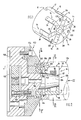
- eine perspektivische Ansicht eines Spanndornes;
- Fig. 2
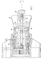
- einen von einem Spindelkopf getragenen Spanndorn im Längsschnitt;
- Fig. 3
- den in Fig. 2 dargestellten Spindelkopf mit einer Entriegelungsvorrichtung;
- Fig. 4
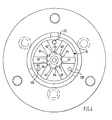
- eine Stirnansicht des in Fig. 2 dargestellten Spindelkopfes;
- Fig. 5
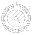
- einen Querschnitt gemäß der Schnittlinie V-V in Fig. 2 und
- Fig. 6
- einen Querschnitt gemäß der Schnittlinie VI-VI in Fig. 2.
- Fig. 1
- a perspective view of a mandrel;
- Fig. 2
- a mandrel carried by a spindle head in longitudinal section;
- Fig. 3
- the spindle head shown in Figure 2 with an unlocking device.
- Fig. 4
- an end view of the spindle head shown in Figure 2;
- Fig. 5
- a cross section along the section line VV in Fig. 2 and
- Fig. 6
- a cross-section along the section line VI-VI in Fig. 2nd
Der in den Figuren dargestellte Spanndorn 10 umfaßt einen Spannkopf 12, der radial ausgerichtete und mit einem Stützflächen 62 aufweisenden Spannkegel 104 zusammenarbeitende Spannkörper 14 mit Flächen 64 (vgl. Fig. 6) hat. Die Stützflächen 62 sind als ebene Abschnitte des sich zu seinem freien Ende hin verjüngenden Spannkegels 104 ausgebildet, die mit den zugeordneten Flächen 64 in einer Ebene liegen.The
Die lamellenartigen Spannkörper 14 haben einen annähernd rechteckförmigen Querschnitt mit Außenseiten 26 und Stirnseiten 38. Die Außenseiten 26 der Spannkörper 14 stehen mit einem Werkstück 126 in Druckverbindung, während die Stirnseiten 38 zum einen aus dem Spanndorn 10 herausragen und zum anderen dem Innenraum des Werkstückes 126 zugekehrt sind. Die lamellenartigen Spannkörper 14 sind in radial im Spannkopf 12 angeordneten Aufnahmen 92 gelagert. Die Aufnahmen 92 weisen Erweiterungen auf, welche als ringförmige Ausnehmung im Spannkopf 12 ausgebildet sind. In diesen Erweiterungen sind elastisch verformbare, die Spannkörper 14 mit dem Spannkopf 12 verbindende Haltekörper 80 aus Gummi oder Kunststoff eingesetzt, so daß die Haltekörper 80 bestrebt sind, die Spannkörper 14 radial nach innen zu versetzen.The
Die in die zur Innenseite des Spannkopfes 12 hin offenen Aufnahmen 92 eingesetzten Spannkörper 14 sind mit dem Spannkopf 12 über Kupplungselenente verbindbar. Die Kupplungselemente sind einerseits als radial an den Spannkörpern 14 angeordnete Vorsprünge 142 und andererseits als im Spannkopf 12 ausgeführte Nuten 140 ausgebildet. Wie insbesondere aus Fig. 2 zu erkennen ist, greifen die Vorsprünge 142 der Spannkörper 14 in die korrespondierenden Nuten 140 des Spannkopfes 12. Die Nuten 140 sind radial nach innen offen und ergeben eine Ringnut, in welche die Vorsprünge 142 der Spannkörper 14 eingehängt sind. Durch die zwischen den einzelnen Spannkörpern 14 angeordneten Haltekörper 80 sind die Spannkörper 14 in dem Spannkopf 12 verspannt. Um durch das Einhängen der Vorsprünge 142 in die Nuten 140 die Genauigkeit der Einstellung nicht negativ zu beeinflussen, ist die radiale Tiefe der Nuten 140 auf den Arbeitsbereich der Spannkörper 14 abgestimmt.The
Der Spannkopf 12 weist weiterhin eine radiale Nut 144 auf, die durch radiale Vorsprünge 200 und 202 an dem dem Werkstück 126 abgewandten Ende gebildet ist. In diese Nut 144 greifen am Zugkörper 156 angeordnete korrespondierende Vorsprünge 204, welche zusammen mit den Vorsprüngen 202 einen Bajonettverschluß bilden, der beim Verdrehen des Spanndorns 10 relativ zu dem Zugkörper 156 lösbar ist. Beim Verdrehen des Spanndorns 10 gelangen die Vorsprünge 204 des Zugkörpers 156 in zwischen den Vorsprüngen 202 angeordnete Ausnehmungen, so daß der Spanndorn 10 von dem Spannkegel 104 abgezogen werden kann. Ein selbständiges Lösen des Spanndorns 10, beispielsweise durch die Trägheitskraft des Spanndorns 10 beim Abbremsen, wird dadurch vermieden, daß die Stützflächen 62 auf den ebenen Flächen 64 des Spannkegels 104 aufliegen. Zum Lösen des Spanndorns 10 müssen die Stützflächen 62 in den Bereich der bogenförmigen Abschnitte des Spannkegels 104 zwischen den ebenen Flächen 64 gedreht werden, wobei die von den Haltekörpern 80 festgehaltenen Spannkörper 14 radial nach außen gedrückt werden. Hierzu muß die von den Haltekörpern 80 aufgebrachte Kraft überwunden werden.The clamping
Zum Lösen des Spanndorns 10 ist eine Entriegelungsvorrichtung 160 vorgesehen, mit der die zum Verschieben der von den Haltekörpern 80 gehaltenen Spannkörper 14 aufzuwendende Kraft erzeugbar ist (siehe Fig. 3).To release the
In dem Spannkegel 104 ist eine axiale Bohrung 106 ausgebildet, an die sich eine in radialer Richtung des Spannkegels 104 erstreckende Ausnehmung 175 anschließt. In der Bohrung 106 und der Ausnehmung 175 ist ein Betätigungsmechanismus angeordnet, der einen in der Bohrung 106 angeordneten Betätigungsbolzen 172 aufweist, welcher mit einem in der Ausnehmung 175 angeordneten Joch 174 drehfest verbunden ist. Ein parallel zu dem Betätigungsbolzen 172 angeordneter Rastbolzen 176 ist an dem Joch 174 befestigt und greift bei auf den Spannkegel 104 aufgesetztem Spanndorn 10 in eine Rastaufnahme 8, welche an dem dem Werkstück 126 abgewandten Ende des Spannkopfes 12 angeordnet ist. Der Rastbolzen 176 sichert den Spanndorn 10 in seiner Arbeitsposition.An
Am konischen Ende des Spannkegels 104 ist die Bohrung 106 aufgeweitet; in der Aufweitung ist eine Feder 170 angeordnet, die den Betätigungsbolzen 172 mit dem daran angeordneten Joch 174 und dem Rastbolzen 176 in Richtung des konischen Endes des Spannkegels drückt. Hierdurch wird der Rastbolzen 176 in die Rastaufnahme 8 gedrückt. Der Betätigungsbolzen 172 ist auf einem Arbeitshub h₂ in axialer Richtung des Spanndornes bewegbar. Dieser Arbeitshub h₂ ist größer als ein Entriegelungshub h₁, durch welchen der Rastbolzen 176 aus der Rastaufnahme 8 herausziehbar ist. Demzufolge ist der Arbeitshub h₂ größer als die Tiefe der Rastaufnahme 8.At the conical end of the clamping
Die Entriegelungsvorrichtung 160 weist einen axial verlaufenden und in die Bohrung 106 eingreifenden Entriegelungsbolzen 162 auf, durch den der Betätigungsbolzen 172 entgegen der Kraft der Feder 170 im Spannkegel 104 verschiebbar ist. Der Entriegelungsbolzen 162 ist mittels einer Druckfeder 164 in der Entriegelungsvorrichtung 160 gelagert. Ferner sind an der Entriegelungsvorrichtung 160 Mitnahmebolzen 166 angeordnet, die in in der Stirnseite des Spanndornes 10 angeordnete, korrespondierende Bohrungen 120 einsetzbar sind. Diese Mitnahmebolzen 166 dienen zur genauen Positionierung der Entriegelungsvorrichtung 160 auf dem Spanndorn 10. Ferner sind neben den Mitnahmebolzen 166 als Haftkörper dienende Magneten 182 angeordnet, die die Entriegelungsvorrichtung 160 lösbar an dem Spanndorn 10 halten.The unlocking
Ein den Spannkegel 104 und den aufgesetzten Spanndorn 10 haltender Spindelkopf 152 ist mittels Schrauben 154 mit einem Grundkörper 158 verbunden, der an der Spindel einer Drehmaschine befestigt wird. Im Grundkörper 158 sind Bohrungen für Schrauben 150 vorgesehen, durch die der Zugkörper 156 mit dem Bajonettverschluß verbunden ist. Der Zugkörper 156 ist in axialer Richtung des Spannkegels 104 bewegbar, wobei der Hub d₁ des Zugkörpers 156 so bemessen ist, daß die Spannkörper 14 entsprechend ihrer Größe maximal ein- und ausgefahren werden können.A
Die in die Aufnahmen 92 des hohlzylindrisch ausgebildeten Spanndorns 10 eingesetzten Spannkörper 14 ragen mit ihren Stirnseiten 38 aus dem Spannkopf 12 heraus, so daß auch Werkstücke eingespannt werden können, die nur eine geringe Ausnehmung aufweisen. Ein lagegenaues Einspannen der Werkstücke wird durch einen parallel zu dem Spanndorn 10 am Spindelkopf 152 lösbar befestigten Anschlag 128 erzielt.The end faces 38 of the clamping
- 88th
- RastaufnahmeRest
- 1010th
- SpanndornMandrel
- 1212
- SpannkopfClamping head
- 1414
-
Spannkörper
Clamping body
- 2626
- AußenseiteOutside
- 3838
- StirnseiteFace
- 6262
- StützflächeSupport surface
- 6464
-
Fläche
area
- 8080
- HaltekörperHolding body
- 9292
- Aufnahmeadmission
- 104104
- SpannkegelClamping cone
- 106106
- Bohrungdrilling
- 120120
- Bohrungdrilling
- 126126
- Werkstückworkpiece
- 128128
-
Anschlag
attack
- 140140
- NutGroove
- 142142
- Vorsprunghead Start
- 144144
- NutGroove
- 150150
- Schraubescrew
- 152152
- SpindelkopfSpindle head
- 154154
- Schraubescrew
- 156156
- ZugkörperTension member
- 158158
-
Grundkörper
Basic body
- 160160
- EntriegelungsvorrichtungUnlocking device
- 162162
- EntriegelungsbolzenUnlocking bolt
- 164164
- DruckfederCompression spring
- 166166
- MitnahmebolzenDriving pin
- 170170
-
Feder
feather
- 172172
-
Betätigungsbolzen
Actuating bolt
- 174174
- Jochyoke
- 175175
- AusnehmungRecess
- 176176
-
Rastbolzen
Locking bolt
- 182182
-
Magnet
magnet
- 200200
- Vorsprunghead Start
- 202202
-
Vorsprung
head Start
- h₁h₁
- EntriegelungshubUnlocking stroke
- h₂h₂
- ArbeitshubWorking stroke
- d₁d₁
- HubStroke
Claims (5)
dadurch gekennzeichnet,
daß die Spannkörper (14) in radialen, zur Vorderseite offenen Aufnahmen (92) eines Spannkopfes (12) angeordnet sind, der mit einer ringförmigen Nut (140) zur Aufnahme der Vorsprünge (142) der Spannkörper (14) versehen und mit dem Zugkörper (156) durch eine schnell lösbare Verbindung (Bajonettverschluß) verbindbar ist, und daß der Spannkopf (12) in seiner Gebrauchsstellung durch eine entriegelbare Verdrehsicherung gegen Verdrehung gehalten ist.Clamping mandrel for machine tools with a plurality of radially aligned clamping bodies (14), each of which is provided with a flat surface (64) and is supported with this surface (64) on an associated support surface (62) of a cross-sectionally polygonal clamping cone (104), with respect to which the clamping bodies (14) can be displaced in the axial direction by means of a tensile body (156) to produce a radial clamping movement, the clamping bodies (14) each being designed with a radially oriented projection (142) for positive entrainment during the axial movement,
characterized by
that the clamping bodies (14) are arranged in radial receptacles (92) of a clamping head (12) which are open to the front and which are provided with an annular groove (140) for receiving the projections (142) of the clamping bodies (14) and with the traction body ( 156) can be connected by a quickly detachable connection (bayonet lock), and that the clamping head (12) is held in its position of use against rotation by means of an unlockable anti-rotation device.
Applications Claiming Priority (2)
| Application Number | Priority Date | Filing Date | Title |
|---|---|---|---|
| DE4004819A DE4004819C1 (en) | 1990-02-16 | 1990-02-16 | |
| DE4004819 | 1990-02-16 |
Publications (1)
| Publication Number | Publication Date |
|---|---|
| EP0442456A1 true EP0442456A1 (en) | 1991-08-21 |
Family
ID=6400284
Family Applications (1)
| Application Number | Title | Priority Date | Filing Date |
|---|---|---|---|
| EP91101983A Withdrawn EP0442456A1 (en) | 1990-02-16 | 1991-02-13 | Expansion mandrel |
Country Status (3)
| Country | Link |
|---|---|
| US (1) | US5133565A (en) |
| EP (1) | EP0442456A1 (en) |
| DE (1) | DE4004819C1 (en) |
Cited By (3)
| Publication number | Priority date | Publication date | Assignee | Title |
|---|---|---|---|---|
| EP1884303A1 (en) | 2006-07-31 | 2008-02-06 | Gebr. Heller Maschinenfabrik GmbH | Method for centring workpieces and device for performing such a method |
| CN103182402A (en) * | 2011-12-29 | 2013-07-03 | 安东石油技术(集团)有限公司 | Tensioning mechanism and manufacturing method thereof and gun barrel |
| CN107350496A (en) * | 2017-09-04 | 2017-11-17 | 福建兵工装备有限公司 | Process the cylindrical special fixture of sleeve part |
Families Citing this family (15)
| Publication number | Priority date | Publication date | Assignee | Title |
|---|---|---|---|---|
| DE19526348C1 (en) * | 1995-07-19 | 1997-02-06 | Preh Elektro Feinmechanik | Method and device for pressing glued film strips |
| DE19543178A1 (en) * | 1995-11-20 | 1997-05-22 | Weh Verbindungstechnik | Collet device |
| US5816581A (en) * | 1997-02-20 | 1998-10-06 | Chase; R. Lee | ID chuck providing workpiece registration and operable by push or pull to attach a workpiece |
| US6279437B1 (en) | 1998-05-26 | 2001-08-28 | Climax Portable Machine Tools, Inc. | Pipe beveling machine |
| US6536316B2 (en) * | 1999-11-29 | 2003-03-25 | Climax Portable Machine Tools, Inc. | Pipe beveling and facing tool |
| US6883407B2 (en) * | 2002-08-30 | 2005-04-26 | Hardinge Inc. | Expanding collet assembly for pick-off spindle |
| US6980874B2 (en) * | 2003-07-01 | 2005-12-27 | General Electric Company | System and method for detecting an anomalous condition in a multi-step process |
| DE20320084U1 (en) * | 2003-12-23 | 2004-03-04 | Hainbuch Gmbh Spannende Technik | Internal clamping device and clamping system equipped with it |
| US8684364B2 (en) * | 2007-01-12 | 2014-04-01 | Sil Han | Positive release collet |
| ITBS20110131A1 (en) * | 2011-09-28 | 2013-03-29 | Gnutti Transfer S P A | MACHINE TOOL WITH SUPPORT AND GRIPPING OF MECHANICAL PARTS |
| CN103286323B (en) * | 2013-05-02 | 2015-06-24 | 中冶陕压重工设备有限公司 | Method for processing long thin-walled sleeve parts by utilizing tyre-expansion type mandrel |
| CA2843304A1 (en) * | 2013-07-22 | 2015-01-22 | Narr Beteiligungs Gmbh | Clamping device |
| DE102016005373A1 (en) * | 2016-04-26 | 2017-10-26 | Westinghouse Electric Germany Gmbh | jig |
| DE102016116666A1 (en) | 2016-09-06 | 2018-03-08 | GDS Präzisionszerspanungs GmbH | Machine tool device |
| ES2948639T3 (en) * | 2017-05-26 | 2023-09-15 | Ralf Dupont | Clamping device and method of clamping a workpiece |
Citations (2)
| Publication number | Priority date | Publication date | Assignee | Title |
|---|---|---|---|---|
| FR2212201A1 (en) * | 1973-01-03 | 1974-07-26 | Tobler Sa | |
| DE9001831U1 (en) * | 1990-02-16 | 1990-04-19 | Schmidt, Claus, 7120 Bietigheim-Bissingen, De |
Family Cites Families (14)
| Publication number | Priority date | Publication date | Assignee | Title |
|---|---|---|---|---|
| US1808288A (en) * | 1925-04-24 | 1931-06-02 | Gen Motors Corp | Work holder |
| US1807264A (en) * | 1929-02-27 | 1931-05-26 | Titan Tool Co | Self-opening tool |
| US2270661A (en) * | 1939-01-12 | 1942-01-20 | New Britain Machine Co | Spring collet |
| US2459899A (en) * | 1944-02-04 | 1949-01-25 | Jacobs Mfg Co | Collet |
| US2817532A (en) * | 1955-10-20 | 1957-12-24 | Woodworth Co N A | Expansion arbor with inclined flats |
| US3332693A (en) * | 1964-07-10 | 1967-07-25 | Armstrong | Collet and holder |
| FR1595583A (en) * | 1968-09-12 | 1970-06-15 | ||
| US3909021A (en) * | 1974-01-14 | 1975-09-30 | Mp Tool & Engineering Co | Collet chuck |
| CA1031940A (en) * | 1975-03-26 | 1978-05-30 | Howard A. Petteys | Expander tool |
| DE2831140A1 (en) * | 1978-07-15 | 1980-01-24 | Hainbuch Wilh Gmbh Co | Two=part collet chuck - includes projections defining channel in which retaining or coupling ring is accommodated |
| US4121847A (en) * | 1977-10-28 | 1978-10-24 | Morawski London T | Collet chuck |
| US4391451A (en) * | 1980-09-17 | 1983-07-05 | Great Lakes Industries, Inc. | Expansible chuck assembly |
| US4416459A (en) * | 1981-06-03 | 1983-11-22 | Morawski Longine V | Collet chuck for splined workpieces |
| DE3629722A1 (en) * | 1986-09-01 | 1988-03-03 | Hainbuch Wilh Gmbh Co | CHUCK |
-
1990
- 1990-02-16 DE DE4004819A patent/DE4004819C1/de not_active Expired - Lifetime
-
1991
- 1991-02-13 EP EP91101983A patent/EP0442456A1/en not_active Withdrawn
- 1991-02-15 US US07/656,300 patent/US5133565A/en not_active Expired - Fee Related
Patent Citations (2)
| Publication number | Priority date | Publication date | Assignee | Title |
|---|---|---|---|---|
| FR2212201A1 (en) * | 1973-01-03 | 1974-07-26 | Tobler Sa | |
| DE9001831U1 (en) * | 1990-02-16 | 1990-04-19 | Schmidt, Claus, 7120 Bietigheim-Bissingen, De |
Cited By (3)
| Publication number | Priority date | Publication date | Assignee | Title |
|---|---|---|---|---|
| EP1884303A1 (en) | 2006-07-31 | 2008-02-06 | Gebr. Heller Maschinenfabrik GmbH | Method for centring workpieces and device for performing such a method |
| CN103182402A (en) * | 2011-12-29 | 2013-07-03 | 安东石油技术(集团)有限公司 | Tensioning mechanism and manufacturing method thereof and gun barrel |
| CN107350496A (en) * | 2017-09-04 | 2017-11-17 | 福建兵工装备有限公司 | Process the cylindrical special fixture of sleeve part |
Also Published As
| Publication number | Publication date |
|---|---|
| US5133565A (en) | 1992-07-28 |
| DE4004819C1 (en) | 1991-08-08 |
Similar Documents
| Publication | Publication Date | Title |
|---|---|---|
| EP0714338B1 (en) | Crankshaft grinding process and device | |
| DE3504905C2 (en) | ||
| EP0442456A1 (en) | Expansion mandrel | |
| DE3324312C2 (en) | Machine tool with tool changing device | |
| DE19857359B4 (en) | Method and device for machining workpieces with thin-walled areas having centric deviations in shape | |
| EP1932607A1 (en) | Workpiece holder for exact positioning on a clamping chuck and clamping device with a chuck and workpiece holder positioned exactly thereon | |
| DE102012209836A1 (en) | Tapping attachment for rigid or synchronous thread cutting | |
| DE4309321C2 (en) | Arrangement for the centered and axially fixed mounting of a rotating body and associated adapter | |
| EP0451360A2 (en) | Clamping device for fixing a tool in a tool holder | |
| EP1233848B1 (en) | Honing tool | |
| CH662964A5 (en) | METHOD FOR MACHINING A WORKPIECE IN A LATHE BETWEEN TIPS AND CLAMPING DEVICE FOR CARRYING OUT THIS METHOD. | |
| EP3093088A1 (en) | Workpiece clamping device including a face driver | |
| EP1884303B1 (en) | Method for centring workpieces and device for performing such a method | |
| DE3400082C2 (en) | ||
| DE19646124C1 (en) | Gripping device for annular workpiece packs | |
| DE907233C (en) | Workpiece holder for machine tools | |
| DE3708363A1 (en) | CHUCK FOR MACHINE TOOLS | |
| EP0412157A1 (en) | Device for clamping a wire rod | |
| DE19941424A1 (en) | Device to clamp work piece to table of machine tool has piston with support webs engaging on inclined wedge surfaces inside housing | |
| DE3705753C2 (en) | ||
| DE2025227B2 (en) | Method and device for clamping and holding elongated work pieces, in particular on induction hard machines | |
| EP1060832A1 (en) | Apparatus and method to hold a workpiece during coaxial grinding | |
| DE3410670A1 (en) | Clamping-tool changing arrangement on machine tools | |
| DE19526755A1 (en) | Clamp mounting for rotating body esp. grinding disc | |
| DE10324670B4 (en) | Tension chuck has one-piece clamping ring fitting axially and rotationally secured on universal adapter with gripper claws entrained through axial movement of spanner towards tool spindle |
Legal Events
| Date | Code | Title | Description |
|---|---|---|---|
| PUAI | Public reference made under article 153(3) epc to a published international application that has entered the european phase |
Free format text: ORIGINAL CODE: 0009012 |
|
| AK | Designated contracting states |
Kind code of ref document: A1 Designated state(s): AT BE CH DE DK ES FR GB GR IT LI LU NL SE |
|
| 17P | Request for examination filed |
Effective date: 19910725 |
|
| RBV | Designated contracting states (corrected) |
Designated state(s): FR GB |
|
| REG | Reference to a national code |
Ref country code: DE Ref legal event code: 8566 |
|
| 17Q | First examination report despatched |
Effective date: 19921221 |
|
| STAA | Information on the status of an ep patent application or granted ep patent |
Free format text: STATUS: THE APPLICATION IS DEEMED TO BE WITHDRAWN |
|
| 18D | Application deemed to be withdrawn |
Effective date: 19930622 |