EP0442136A1 - Heizkeilschweissgerät - Google Patents
Heizkeilschweissgerät Download PDFInfo
- Publication number
- EP0442136A1 EP0442136A1 EP90125325A EP90125325A EP0442136A1 EP 0442136 A1 EP0442136 A1 EP 0442136A1 EP 90125325 A EP90125325 A EP 90125325A EP 90125325 A EP90125325 A EP 90125325A EP 0442136 A1 EP0442136 A1 EP 0442136A1
- Authority
- EP
- European Patent Office
- Prior art keywords
- welding
- roller
- wedge
- pressure
- rollers
- Prior art date
- Legal status (The legal status is an assumption and is not a legal conclusion. Google has not performed a legal analysis and makes no representation as to the accuracy of the status listed.)
- Withdrawn
Links
- 238000003466 welding Methods 0.000 title claims abstract description 30
- 238000010438 heat treatment Methods 0.000 title claims description 14
- 238000012360 testing method Methods 0.000 claims abstract description 17
- 238000007789 sealing Methods 0.000 claims description 9
- 239000012528 membrane Substances 0.000 abstract description 6
- 238000003825 pressing Methods 0.000 abstract description 4
- 238000004078 waterproofing Methods 0.000 abstract description 4
- 230000000694 effects Effects 0.000 description 3
- 239000000463 material Substances 0.000 description 3
- 238000000034 method Methods 0.000 description 2
- 230000002411 adverse Effects 0.000 description 1
- 230000006735 deficit Effects 0.000 description 1
- 230000002349 favourable effect Effects 0.000 description 1
- 238000007689 inspection Methods 0.000 description 1
- 239000011344 liquid material Substances 0.000 description 1
- 238000004519 manufacturing process Methods 0.000 description 1
- 239000003566 sealing material Substances 0.000 description 1
- 238000003860 storage Methods 0.000 description 1
- 238000011144 upstream manufacturing Methods 0.000 description 1
Images
Classifications
-
- B—PERFORMING OPERATIONS; TRANSPORTING
- B29—WORKING OF PLASTICS; WORKING OF SUBSTANCES IN A PLASTIC STATE IN GENERAL
- B29C—SHAPING OR JOINING OF PLASTICS; SHAPING OF MATERIAL IN A PLASTIC STATE, NOT OTHERWISE PROVIDED FOR; AFTER-TREATMENT OF THE SHAPED PRODUCTS, e.g. REPAIRING
- B29C65/00—Joining or sealing of preformed parts, e.g. welding of plastics materials; Apparatus therefor
- B29C65/02—Joining or sealing of preformed parts, e.g. welding of plastics materials; Apparatus therefor by heating, with or without pressure
- B29C65/18—Joining or sealing of preformed parts, e.g. welding of plastics materials; Apparatus therefor by heating, with or without pressure using heated tools
- B29C65/20—Joining or sealing of preformed parts, e.g. welding of plastics materials; Apparatus therefor by heating, with or without pressure using heated tools with direct contact, e.g. using "mirror"
-
- B—PERFORMING OPERATIONS; TRANSPORTING
- B29—WORKING OF PLASTICS; WORKING OF SUBSTANCES IN A PLASTIC STATE IN GENERAL
- B29C—SHAPING OR JOINING OF PLASTICS; SHAPING OF MATERIAL IN A PLASTIC STATE, NOT OTHERWISE PROVIDED FOR; AFTER-TREATMENT OF THE SHAPED PRODUCTS, e.g. REPAIRING
- B29C66/00—General aspects of processes or apparatus for joining preformed parts
- B29C66/01—General aspects dealing with the joint area or with the area to be joined
- B29C66/05—Particular design of joint configurations
- B29C66/10—Particular design of joint configurations particular design of the joint cross-sections
- B29C66/11—Joint cross-sections comprising a single joint-segment, i.e. one of the parts to be joined comprising a single joint-segment in the joint cross-section
- B29C66/112—Single lapped joints
- B29C66/1122—Single lap to lap joints, i.e. overlap joints
-
- B—PERFORMING OPERATIONS; TRANSPORTING
- B29—WORKING OF PLASTICS; WORKING OF SUBSTANCES IN A PLASTIC STATE IN GENERAL
- B29C—SHAPING OR JOINING OF PLASTICS; SHAPING OF MATERIAL IN A PLASTIC STATE, NOT OTHERWISE PROVIDED FOR; AFTER-TREATMENT OF THE SHAPED PRODUCTS, e.g. REPAIRING
- B29C66/00—General aspects of processes or apparatus for joining preformed parts
- B29C66/40—General aspects of joining substantially flat articles, e.g. plates, sheets or web-like materials; Making flat seams in tubular or hollow articles; Joining single elements to substantially flat surfaces
- B29C66/41—Joining substantially flat articles ; Making flat seams in tubular or hollow articles
- B29C66/43—Joining a relatively small portion of the surface of said articles
-
- B—PERFORMING OPERATIONS; TRANSPORTING
- B29—WORKING OF PLASTICS; WORKING OF SUBSTANCES IN A PLASTIC STATE IN GENERAL
- B29C—SHAPING OR JOINING OF PLASTICS; SHAPING OF MATERIAL IN A PLASTIC STATE, NOT OTHERWISE PROVIDED FOR; AFTER-TREATMENT OF THE SHAPED PRODUCTS, e.g. REPAIRING
- B29C66/00—General aspects of processes or apparatus for joining preformed parts
- B29C66/70—General aspects of processes or apparatus for joining preformed parts characterised by the composition, physical properties or the structure of the material of the parts to be joined; Joining with non-plastics material
- B29C66/73—General aspects of processes or apparatus for joining preformed parts characterised by the composition, physical properties or the structure of the material of the parts to be joined; Joining with non-plastics material characterised by the intensive physical properties of the material of the parts to be joined, by the optical properties of the material of the parts to be joined, by the extensive physical properties of the parts to be joined, by the state of the material of the parts to be joined or by the material of the parts to be joined being a thermoplastic or a thermoset
- B29C66/731—General aspects of processes or apparatus for joining preformed parts characterised by the composition, physical properties or the structure of the material of the parts to be joined; Joining with non-plastics material characterised by the intensive physical properties of the material of the parts to be joined, by the optical properties of the material of the parts to be joined, by the extensive physical properties of the parts to be joined, by the state of the material of the parts to be joined or by the material of the parts to be joined being a thermoplastic or a thermoset characterised by the intensive physical properties of the material of the parts to be joined
- B29C66/7318—Permeability to gases or liquids
- B29C66/73185—Permeability to gases or liquids non-permeable
- B29C66/73187—Permeability to gases or liquids non-permeable to liquids
-
- B—PERFORMING OPERATIONS; TRANSPORTING
- B29—WORKING OF PLASTICS; WORKING OF SUBSTANCES IN A PLASTIC STATE IN GENERAL
- B29C—SHAPING OR JOINING OF PLASTICS; SHAPING OF MATERIAL IN A PLASTIC STATE, NOT OTHERWISE PROVIDED FOR; AFTER-TREATMENT OF THE SHAPED PRODUCTS, e.g. REPAIRING
- B29C66/00—General aspects of processes or apparatus for joining preformed parts
- B29C66/80—General aspects of machine operations or constructions and parts thereof
- B29C66/83—General aspects of machine operations or constructions and parts thereof characterised by the movement of the joining or pressing tools
- B29C66/836—Moving relative to and tangentially to the parts to be joined, e.g. transversely to the displacement of the parts to be joined, e.g. using a X-Y table
- B29C66/8362—Rollers, cylinders or drums moving relative to and tangentially to the parts to be joined
-
- B—PERFORMING OPERATIONS; TRANSPORTING
- B29—WORKING OF PLASTICS; WORKING OF SUBSTANCES IN A PLASTIC STATE IN GENERAL
- B29C—SHAPING OR JOINING OF PLASTICS; SHAPING OF MATERIAL IN A PLASTIC STATE, NOT OTHERWISE PROVIDED FOR; AFTER-TREATMENT OF THE SHAPED PRODUCTS, e.g. REPAIRING
- B29C66/00—General aspects of processes or apparatus for joining preformed parts
- B29C66/80—General aspects of machine operations or constructions and parts thereof
- B29C66/81—General aspects of the pressing elements, i.e. the elements applying pressure on the parts to be joined in the area to be joined, e.g. the welding jaws or clamps
- B29C66/814—General aspects of the pressing elements, i.e. the elements applying pressure on the parts to be joined in the area to be joined, e.g. the welding jaws or clamps characterised by the design of the pressing elements, e.g. of the welding jaws or clamps
- B29C66/8141—General aspects of the pressing elements, i.e. the elements applying pressure on the parts to be joined in the area to be joined, e.g. the welding jaws or clamps characterised by the design of the pressing elements, e.g. of the welding jaws or clamps characterised by the surface geometry of the part of the pressing elements, e.g. welding jaws or clamps, coming into contact with the parts to be joined
- B29C66/81411—General aspects of the pressing elements, i.e. the elements applying pressure on the parts to be joined in the area to be joined, e.g. the welding jaws or clamps characterised by the design of the pressing elements, e.g. of the welding jaws or clamps characterised by the surface geometry of the part of the pressing elements, e.g. welding jaws or clamps, coming into contact with the parts to be joined characterised by its cross-section, e.g. transversal or longitudinal, being non-flat
- B29C66/81415—General aspects of the pressing elements, i.e. the elements applying pressure on the parts to be joined in the area to be joined, e.g. the welding jaws or clamps characterised by the design of the pressing elements, e.g. of the welding jaws or clamps characterised by the surface geometry of the part of the pressing elements, e.g. welding jaws or clamps, coming into contact with the parts to be joined characterised by its cross-section, e.g. transversal or longitudinal, being non-flat being bevelled
- B29C66/81417—General aspects of the pressing elements, i.e. the elements applying pressure on the parts to be joined in the area to be joined, e.g. the welding jaws or clamps characterised by the design of the pressing elements, e.g. of the welding jaws or clamps characterised by the surface geometry of the part of the pressing elements, e.g. welding jaws or clamps, coming into contact with the parts to be joined characterised by its cross-section, e.g. transversal or longitudinal, being non-flat being bevelled being V-shaped
-
- B—PERFORMING OPERATIONS; TRANSPORTING
- B29—WORKING OF PLASTICS; WORKING OF SUBSTANCES IN A PLASTIC STATE IN GENERAL
- B29C—SHAPING OR JOINING OF PLASTICS; SHAPING OF MATERIAL IN A PLASTIC STATE, NOT OTHERWISE PROVIDED FOR; AFTER-TREATMENT OF THE SHAPED PRODUCTS, e.g. REPAIRING
- B29C66/00—General aspects of processes or apparatus for joining preformed parts
- B29C66/80—General aspects of machine operations or constructions and parts thereof
- B29C66/81—General aspects of the pressing elements, i.e. the elements applying pressure on the parts to be joined in the area to be joined, e.g. the welding jaws or clamps
- B29C66/814—General aspects of the pressing elements, i.e. the elements applying pressure on the parts to be joined in the area to be joined, e.g. the welding jaws or clamps characterised by the design of the pressing elements, e.g. of the welding jaws or clamps
- B29C66/8141—General aspects of the pressing elements, i.e. the elements applying pressure on the parts to be joined in the area to be joined, e.g. the welding jaws or clamps characterised by the design of the pressing elements, e.g. of the welding jaws or clamps characterised by the surface geometry of the part of the pressing elements, e.g. welding jaws or clamps, coming into contact with the parts to be joined
- B29C66/81411—General aspects of the pressing elements, i.e. the elements applying pressure on the parts to be joined in the area to be joined, e.g. the welding jaws or clamps characterised by the design of the pressing elements, e.g. of the welding jaws or clamps characterised by the surface geometry of the part of the pressing elements, e.g. welding jaws or clamps, coming into contact with the parts to be joined characterised by its cross-section, e.g. transversal or longitudinal, being non-flat
- B29C66/81421—General aspects of the pressing elements, i.e. the elements applying pressure on the parts to be joined in the area to be joined, e.g. the welding jaws or clamps characterised by the design of the pressing elements, e.g. of the welding jaws or clamps characterised by the surface geometry of the part of the pressing elements, e.g. welding jaws or clamps, coming into contact with the parts to be joined characterised by its cross-section, e.g. transversal or longitudinal, being non-flat being convex or concave
- B29C66/81422—General aspects of the pressing elements, i.e. the elements applying pressure on the parts to be joined in the area to be joined, e.g. the welding jaws or clamps characterised by the design of the pressing elements, e.g. of the welding jaws or clamps characterised by the surface geometry of the part of the pressing elements, e.g. welding jaws or clamps, coming into contact with the parts to be joined characterised by its cross-section, e.g. transversal or longitudinal, being non-flat being convex or concave being convex
-
- B—PERFORMING OPERATIONS; TRANSPORTING
- B29—WORKING OF PLASTICS; WORKING OF SUBSTANCES IN A PLASTIC STATE IN GENERAL
- B29C—SHAPING OR JOINING OF PLASTICS; SHAPING OF MATERIAL IN A PLASTIC STATE, NOT OTHERWISE PROVIDED FOR; AFTER-TREATMENT OF THE SHAPED PRODUCTS, e.g. REPAIRING
- B29C66/00—General aspects of processes or apparatus for joining preformed parts
- B29C66/80—General aspects of machine operations or constructions and parts thereof
- B29C66/81—General aspects of the pressing elements, i.e. the elements applying pressure on the parts to be joined in the area to be joined, e.g. the welding jaws or clamps
- B29C66/814—General aspects of the pressing elements, i.e. the elements applying pressure on the parts to be joined in the area to be joined, e.g. the welding jaws or clamps characterised by the design of the pressing elements, e.g. of the welding jaws or clamps
- B29C66/8145—General aspects of the pressing elements, i.e. the elements applying pressure on the parts to be joined in the area to be joined, e.g. the welding jaws or clamps characterised by the design of the pressing elements, e.g. of the welding jaws or clamps characterised by the constructional aspects of the pressing elements, e.g. of the welding jaws or clamps
- B29C66/81463—General aspects of the pressing elements, i.e. the elements applying pressure on the parts to be joined in the area to be joined, e.g. the welding jaws or clamps characterised by the design of the pressing elements, e.g. of the welding jaws or clamps characterised by the constructional aspects of the pressing elements, e.g. of the welding jaws or clamps comprising a plurality of single pressing elements, e.g. a plurality of sonotrodes, or comprising a plurality of single counter-pressing elements, e.g. a plurality of anvils, said plurality of said single elements being suitable for making a single joint
- B29C66/81469—General aspects of the pressing elements, i.e. the elements applying pressure on the parts to be joined in the area to be joined, e.g. the welding jaws or clamps characterised by the design of the pressing elements, e.g. of the welding jaws or clamps characterised by the constructional aspects of the pressing elements, e.g. of the welding jaws or clamps comprising a plurality of single pressing elements, e.g. a plurality of sonotrodes, or comprising a plurality of single counter-pressing elements, e.g. a plurality of anvils, said plurality of said single elements being suitable for making a single joint one placed next to the other in a single line transverse to the feed direction, e.g. shoulder to shoulder sonotrodes
Definitions
- the invention relates to a hot wedge welding device with pressure rollers for welding overlapping sealing sheets made of plastic, wherein the warm heating wedge for plasticizing the welding surfaces is brought between them and the plasticized welding surfaces are then pressed against one another with welding pressure, and the pressure rollers both ensure that the sealing sheets touch the heating wedge as well as cause the welding pressure.
- waterproofing membranes are limited for reasons of manufacture, transport and handling. Therefore, the desired seals are assembled from individual sealing sheets.
- the sealing sheets are laid overlapping and welded together at the overlap edges.
- This tried and tested welding technique is based on the use of a heating wedge.
- the heating wedge is heated and brought into contact with the welding surfaces. This also heats up the welding surfaces of the waterproofing membrane.
- the sealing sheets are then pressed together on the plasticized welding surfaces. Ideally, this causes a homogeneous material transfer from one sealing membrane to the other, so that a firm connection is created after the welded joint has cooled.
- Double seams are usually produced for welding seam testing when sealing waterproofing membranes for landfill base seals. There is a test channel between the two seams of a double seam. A pressure medium is applied to the test channel. If the weld seams withstand the pressure for a certain period of time, the weld seams can be assumed to be of sufficient quality.
- the roles are therefore divided into individual sections, which in turn are ball or roller or needle bearing.
- the pressure rollers in the area of the heating wedge, the critical area, namely the pressing of the welding surfaces and the welding pressure, are far upstream and the pressing on the heating wedge can only have a minor influence on the weld seam
- the measure according to the invention has an excellent effect the weld seam can be achieved.
- the section-by-section division and independent storage of the sections ensures that the rollers have no adverse influence, for. B. can go out in the form of braking torque.
- Stiff roller sections can undesirably cause relative movements of the different welding surfaces to one another; likewise, the braking effect of poorly moving rollers can cause excessive and uneven pressing of these rollers and the pushing away of liquid material. The details still need to be examined, but the results are reliable. In this respect, the pressure rollers designed according to the invention have an unexpected effect.
- Each of the rollers has at least two sections which, when producing weld seams with a test channel, have a distance from one another which corresponds to the test channel width or a recess which corresponds to the test channel width.
- An independently rotatably mounted section of the roller can be arranged on each side of the test channel. Preferably, several sections are arranged on each side of the test channel.
- roller / ball bearings themselves form the roller section. They are only held with a bolt.
- roller sections are arranged next to one another on both sides of the test channel and these roller sections are at a distance from one another.
- three roller sections or roller / ball bearings are provided on both sides of the test channel, which are also at a short distance from one another.
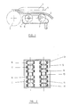
- Fig. 1 shows a schematic partial view of a hot wedge welding device with a hot wedge 1, pressure rollers 3, 6 and 7. Of the pressure rollers 3, only the pressure rollers 3 below the line of symmetry 4 is shown, as are the pressure rollers 6 and 7 arranged below the line of symmetry 4 Pinch rollers 6 and 7 are held in a cage 5.
- the sealing material 2 to be welded is pressed against the heated heating wedge 1, so that the plastic surfaces coming into contact with the heating wedge 1 heat up and are plasticized if the heating wedge temperature is sufficient.
- the sealing membrane edges guided on both sides of the heating wedge 1 are then pressed together with the aid of the pressure rollers 3 under appropriate welding pressure.
- the pressure rollers 6 and 7 consist of bolts 10 on which encapsulated roller / ball bearings 11 are seated.
- roller / ball bearings are provided for each roller 5 or 6.
- the six roller / ball bearings each form groups of three, which are at a distance 12 from one another corresponding to the test channel width.
- the roller / ball bearings 11 are at a short distance from one another.
Landscapes
- Engineering & Computer Science (AREA)
- Mechanical Engineering (AREA)
- Lining Or Joining Of Plastics Or The Like (AREA)
Abstract
An Heizkeilschweißgeräten werden die Andruckrollen (3,6,7) zum Andrücken von Kunststoffabdichtungsbahnen (2) den erwärmten Heizkeil (1) jeweils durch mehrere unabhängig voneinander drehbewegliche Rollen-/Kugellager gebildet, die im Bereich des Prüfkanales einen dem Prüfkanal entsprechenden Abstand aufweisen. <IMAGE>
Description
- Die Erfindung betrifft ein Heizkeilschweißgerät mit Andruckrollen zum Schweißen von einander überlappenden Abdichtungsbahnen aus Kunststoff, wobei der warme Heizkeil zur Plastifizierung der Schweißflächen zwischen diese gebracht und die plastifizierten Schweißflächen anschließend mit Schweißdruck gegeneinander gedrückt werden und wobei die Andruckrollen sowohl eine Berührung der Abdichtungsbahnen mit dem Heizkeil gewährleisten als auch den Schweißdruck verursachen.
- Die Abmessungen von Abdichtungsbahnen sind aus Gründen der Herstellung, des Transportes und des Handlings begrenzt. Deshalb werden die gewünschten Abdichtungen aus einzelnen Abdichtungsbahnen zusammengesetzt. Die Abdichtungsbahnen werden dabei überlappend verlegt und an den Überlappungsrändern miteinander verschweißt. Es gibt zwar eine Reihe von Schweißtechniken, aber nur eine in großem Umfang erprobte und bewährte Schweißtechnik. Diese erprobte und bewährte Schweißtechnik basiert auf der Verwendung eines Heizkeiles. Der Heizkeil wird erwärmt und mit den Schweißflächen in Berührung gebracht. Dadurch erwärmen sich auch die Schweißflächen der Abdichtungsbahnen. Anschließend werden die Abdichtungsbahnen an den plastifizierten Schweißflächen aneinandergedrückt. Dies bewirkt im Idealfall einen homogenen Materialübergang von einer Abdichtungsbahn in die andere, so daß nach dem Erkalten der Schweißverbindung eine feste Verbindung entsteht.
- Zur Schweißnahtprüfung werden beim Schweißen von Abdichtungsbahnen für Deponiebasisabdichtungen üblicherweise Doppelnähte erzeugt. Zwischen den beiden Nähten einer Doppelnaht besteht ein Prüfkanal. Der Prüfkanal wird mit einem Druckmedium beaufschlagt. Wenn die Schweißnähte über eine bestimmte Dauer dem Druck standhalten, kann von ausreichender Qualität der Schweißnähte ausgegangen werden.
- Diese Prüfung der Schweißnaht ist jedoch auch abhängig von der Ausführung der Schweißnaht. Es hat sich gezeigt, daß die Schweißnähte zum Teil äußerst ungenau geraten. Häufig läuft plastifiziertes Kunststoff material in den Prüfkanal und verschließt diesen. Dadurch ist nicht immer ein offener Prüfkanal gewährleistet. Der Erfindung liegt daher die Aufgabe zugrunde, die Schweißnaht zu verbessern. Dabei geht die Erfindung von der Überlegung aus, daß weniger das Kunststoffmaterial als die Mechanik der Schweißgeräte Ursache für die Schweißprobleme ist. Des weiteren werden die Gründe in der bisherigen Form der Andruckrollen vermutet. Diese bisherigen Andruckrollen erstrecken sich üblicherweise als einteilige Rollen über die gesamte Breite der Doppelnaht. Jede Unebenheit und auch jede Beeinträchtigung der Rollen-/Kugellagerung in einem Bereich beeinträchtigen zugleich die Rollenfunktion in ihrer Gesamtheit. Nach der Erfindung sind deshalb die Rollen in Einzelabschnitte unterteilt, die ihrerseits kugel- oder rollen- oder nadelgelagert sind. Obwohl die Andruckrollen im Bereich des Heizkeiles, dem kritischen Bereich, nämlich dem Andrücken der Schweißflächen und der Schweißdruck weit vorgeordnet sind und das Andrücken am Heizkeil nur geringen Einfluß auf die Schweißnaht haben kann, zeigt sich überraschenderweise, daß mit der erfindungsgemäßen Maßnahme eine hervorragende Wirkung auf die Schweißnaht erzielt werden kann. Durch die abschnittsweise Aufteilung und voneinander unabhängige Lagerung der Abschnitte wird sichergestellt, daß von den Rollen kein nachteiliger Einfluß, z. B. in Form von Bremsmomenten ausgehen kann. Schwergängige Rollenabschnitte können unerwünscht Relativbewegungen der unterschiedlichen Schweißflächen zueinander verursachen; desgleichen kann die Bremswirkung schlechtgängiger Rollen übermäßiges und ungleichmäßiges Andrücken dieser Rollen sowie das Wegdrücken von Flüssigmaterial verursachen. Die Einzelheiten bedürfen noch einer Untersuchung, die Ergebnisse sind jedoch zuverlässig. Insofern haben die erfindungsgemäß ausgestalteten Andruckrollen eine unerwartete Wirkung.
- Jede der Rollen besitzt mindestens zwei Abschnitte, die bei Erzeugung von Schweißnähten mit einem Prüfkanal einen der Prüfkanalbreite entsprechenden Abstand voneinander oder eine der Prüfkanalbreite entsprechende Ausnehmung besitzen. Dabei kann auf jeder Seite des Prüfkanals ein unabhängig drehbeweglich gelagerter Abschnitt der Rolle angeordnet sein. Vorzugsweise sind auf jeder Seite des Prüfkanals mehrere Abschnitte angeordnet.
- Von besonderem Vorteil ist die Verwendung von handelsüblichen Rollen-/Kugellagern als Andruckrollenabschnitte. Die Rollen-/Kugellager bilden dabei selbst den Rollenabschnitt. Sie werden lediglich mit einem Bolzen gehalten. Günstige Verhältnisse stellen sich vor allem dann ein, wenn beiderseits des Prüfkanals mehrere Rollenabschnitte nebeneinander angeordnet sind und diese Rollenabschnitte einen Abstand voneinander aufweisen. Vorzugsweise sind beiderseits des Prüfkanals je drei Rollenabschnitte bzw. Rollen-/Kugellager vorgesehen, die untereinander gleichfalls einen geringen Abstand aufweisen.
- In der Zeichnung ist ein Ausführungsbeispiel der Erfindung dargestellt.
- Fig. 1 zeigt eine schematische Teilansicht eines Heizkeilschweißgerätes mit einem Heizkeil 1, Andruckrollen 3, 6 und 7. Von den Andruckrollen 3 ist nur die unterhalb der Symmetrielinie 4 liegende Andruckrollen 3 dargestellt, desgleichen die unterhalb der Symmetrielinie 4 angeordneten Andruckrollen 6 und 7. Die Andruckrollen 6 und 7 sind in einem Käfig 5 gehalten. Mittels der Andruckrollen 6 und 7 wird das zu verschweißende Abdichtungsmaterial 2 gegen den erwärmten Heizkeil 1 gedrückt, so daß sich die mit dem Heizkeil 1 in Berührung kommenden Kunststoffflächen erwärmen und bei ausreichender Heizkeiltemperatur plastifiziert werden. Nach Verlassen des Heizkeiles werden dann die beiderseits des Heizkeiles 1 geführten Abdichtungsbahnenränder mit Hilfe der Andruckrollen 3 unter entsprechendem Schweißdruck aneinandergedrückt.
- Nach Fig. 2 bestehen die Andruckrollen 6 und 7 aus Bolzen 10, auf denen gekapselte Rollen-/Kugellager 11 sitzen.
- Es sind jeweils sechs Rollen-/Kugellager je Rolle 5 bzw. 6 vorgesehen. Die sechs Rollen-/Kugellager bilden jeweils Dreiergruppen, die einen der Prüfkanalbreite entsprechenden Abstand 12 voneinander aufweisen. Im übrigen besitzen auch die Rollen-/Kugellager 11 untereinander einen geringen Abstand.
Claims (4)
- Heizkeilschweißgerät zum Schweißen von einander überlappenden Abdichtungsbahnen mit Andruckrollen, wobei der warme Heizkeil zur Plastifizierung der Schweißflächen zwischen diese gebracht wird und die plastifizierten Schweißflächen anschließend mit Schweißdruck gegeneinander gedrückt werden und wobei Andruckrollen sowohl eine Berührung mit dem Heizkeil gewährleisten als auch den Schweißdruck verursachen, dadurch gekennzeichnet, daß die Rollen (5, 6) einzelne rollengelagerte oder nadelgelagerte Abschnitte (11) aufweisen.
- Heizkeilschweißgerät nach Anspruch 1, dadurch gekennzeichnet, daß jede Rolle (5, 6) mindestens zwei Abschnitte mit einem Abstand (12) besitzt, der bei Erzeugung einer Schweißnaht mit einem Prüfkanal der Prüfkanalbreite entspricht.
- Heizkeilschweißgerät nach Anspruch 2, dadurch gekennzeichnet, daß die Rollen (5, 6) durch Bolzen (10) und Rollen-/Kugellager (11) gebildet werden.
- Heizkeilschweißgerät nach Anspruch 3, gekennzeichnet durch gekapselte Lager.
Applications Claiming Priority (2)
| Application Number | Priority Date | Filing Date | Title |
|---|---|---|---|
| DE4004658A DE4004658A1 (de) | 1990-02-15 | 1990-02-15 | Heizkeilschweissgeraet |
| DE4004658 | 1990-02-15 |
Publications (1)
| Publication Number | Publication Date |
|---|---|
| EP0442136A1 true EP0442136A1 (de) | 1991-08-21 |
Family
ID=6400192
Family Applications (1)
| Application Number | Title | Priority Date | Filing Date |
|---|---|---|---|
| EP90125325A Withdrawn EP0442136A1 (de) | 1990-02-15 | 1990-12-22 | Heizkeilschweissgerät |
Country Status (2)
| Country | Link |
|---|---|
| EP (1) | EP0442136A1 (de) |
| DE (1) | DE4004658A1 (de) |
Citations (3)
| Publication number | Priority date | Publication date | Assignee | Title |
|---|---|---|---|---|
| DD18262A (de) * | ||||
| AT351754B (de) * | 1976-01-30 | 1979-08-10 | Sarna Kunststoff Ag | Schweissgeraet zum verschweissen von kunststoff- bahnen |
| AT363676B (de) * | 1976-12-22 | 1981-08-25 | Sarna Kunststoff Ag | Schweissgeraet zum verschweissen von kunststoffbahnen |
Family Cites Families (3)
| Publication number | Priority date | Publication date | Assignee | Title |
|---|---|---|---|---|
| DE1752598U (de) * | 1957-07-17 | 1957-09-19 | Anton Kolb | Handschweissvorrichtung fuer thermoplastische folien. |
| AT381275B (de) * | 1984-11-13 | 1986-09-25 | Neumueller Walter | Schweissgeraet |
| US4834827A (en) * | 1986-06-05 | 1989-05-30 | Obeda Edward G | Apparatus and method for ultrasonically joining sheets of thermoplastic materials |
-
1990
- 1990-02-15 DE DE4004658A patent/DE4004658A1/de not_active Withdrawn
- 1990-12-22 EP EP90125325A patent/EP0442136A1/de not_active Withdrawn
Patent Citations (3)
| Publication number | Priority date | Publication date | Assignee | Title |
|---|---|---|---|---|
| DD18262A (de) * | ||||
| AT351754B (de) * | 1976-01-30 | 1979-08-10 | Sarna Kunststoff Ag | Schweissgeraet zum verschweissen von kunststoff- bahnen |
| AT363676B (de) * | 1976-12-22 | 1981-08-25 | Sarna Kunststoff Ag | Schweissgeraet zum verschweissen von kunststoffbahnen |
Also Published As
| Publication number | Publication date |
|---|---|
| DE4004658A1 (de) | 1991-08-29 |
Similar Documents
| Publication | Publication Date | Title |
|---|---|---|
| DE2539347B2 (de) | Schweissgeraet fuer thermoplastische gegenstaende | |
| DE2243465A1 (de) | Vorrichtung zur ausuebung einer flaechenpressung | |
| DE3037019A1 (de) | Schwebstoffiltereinsatz aus gefaltetem schwebstoffiltermaterial fuer schwebstoffilter und ein verfahren zu seiner herstellung | |
| DD143411A5 (de) | Formband fuer eine presse zur ausuebung einer flaechenpressung | |
| DE1645387B2 (de) | Vorrichtung zum kontinuierlichen Gießen eines polymerisierbaren organischen Monomers zu steifen Platten | |
| DE2845271A1 (de) | Schweissbacke fuer verpackungsmaschinen | |
| EP0442136A1 (de) | Heizkeilschweissgerät | |
| DE2163731C3 (de) | ||
| DE2545624C3 (de) | Presse zur Ausübung einer Flächenpressung | |
| DE3901366C2 (de) | Verfahren und Vorrichtung zur Beheizung einer kontinuierlich arbeitenden Heizplattenpresse | |
| DE1964523C (de) | Verfahren zum Pressen von textlien Gewebebahnen mittels Heizplatten und Heizplattenpresse zur Durchführung dieses Verfahrens | |
| DE2755534A1 (de) | Vorrichtung zum vulkanisieren von foerderbaendern o.dgl. | |
| DE2355797B2 (de) | Presse zur Ausübung einer Flächenpressung | |
| DE2058927A1 (de) | Verfahren und Vorrichtung zur kontinuierlichen Schutzgasschweissung | |
| DE2548382C3 (de) | Vorrichtung zum Erwärmen einer Kunststoff-Folienbahn | |
| DE2114736A1 (de) | Vorrichtung zur Ausübung einer Flächenpressung | |
| DE2032028C3 (de) | Verfahren und Vorrichtung zum Herstellen von Asbest-Kautschuk-Hochdruck-Dichtungsplatten | |
| DE3040017C2 (de) | ||
| DE2700221B2 (de) | Verfahren und Vorrichtung zur Herstellung von Plattenwärmetauschern | |
| CH377527A (de) | Geschichtete Folie | |
| DE1813554C3 (de) | Vorrichtung zur Mikrowellenheizung eines langgestreckten dielektrischen Körpers | |
| DE2407447C3 (de) | Vorrichtung zum Verbinden der Ränder von großflächigen Gummi- oder Kunststoffplanen | |
| DE940428C (de) | Verfahren und Vorrichtung zum serienweisen Herstellen von Schallbaendern | |
| DE1953883A1 (de) | Verfahren zum flaechigen Verschweissen von aufgeheizten Warenbahnen,insbesondere von thermoplastischen Kunststoff-Folien,sowie Vorrichtung zur Durchfuehrung des Verfahrens | |
| DE2227690C3 (de) | Vorrichtung zum Herstellen einer Verbundbahn mit abgeschlossenen luftgefullten Zellen für Polster- oder Dämmzwecke |
Legal Events
| Date | Code | Title | Description |
|---|---|---|---|
| PUAI | Public reference made under article 153(3) epc to a published international application that has entered the european phase |
Free format text: ORIGINAL CODE: 0009012 |
|
| 17P | Request for examination filed |
Effective date: 19901222 |
|
| AK | Designated contracting states |
Kind code of ref document: A1 Designated state(s): AT BE CH DE FR LI NL |
|
| STAA | Information on the status of an ep patent application or granted ep patent |
Free format text: STATUS: THE APPLICATION IS DEEMED TO BE WITHDRAWN |
|
| 18D | Application deemed to be withdrawn |
Effective date: 19930630 |