EP0441910B1 - Monolithischer beschleunigungsmesser mit biegsam montiertem kraftwandler - Google Patents
Monolithischer beschleunigungsmesser mit biegsam montiertem kraftwandler Download PDFInfo
- Publication number
- EP0441910B1 EP0441910B1 EP90911014A EP90911014A EP0441910B1 EP 0441910 B1 EP0441910 B1 EP 0441910B1 EP 90911014 A EP90911014 A EP 90911014A EP 90911014 A EP90911014 A EP 90911014A EP 0441910 B1 EP0441910 B1 EP 0441910B1
- Authority
- EP
- European Patent Office
- Prior art keywords
- proof mass
- transducer
- axis
- force transducer
- force
- Prior art date
- Legal status (The legal status is an assumption and is not a legal conclusion. Google has not performed a legal analysis and makes no representation as to the accuracy of the status listed.)
- Expired - Lifetime
Links
Images

Classifications
-
- G—PHYSICS
- G01—MEASURING; TESTING
- G01P—MEASURING LINEAR OR ANGULAR SPEED, ACCELERATION, DECELERATION, OR SHOCK; INDICATING PRESENCE, ABSENCE, OR DIRECTION, OF MOVEMENT
- G01P15/00—Measuring acceleration; Measuring deceleration; Measuring shock, i.e. sudden change of acceleration
- G01P15/02—Measuring acceleration; Measuring deceleration; Measuring shock, i.e. sudden change of acceleration by making use of inertia forces using solid seismic masses
- G01P15/08—Measuring acceleration; Measuring deceleration; Measuring shock, i.e. sudden change of acceleration by making use of inertia forces using solid seismic masses with conversion into electric or magnetic values
- G01P15/097—Measuring acceleration; Measuring deceleration; Measuring shock, i.e. sudden change of acceleration by making use of inertia forces using solid seismic masses with conversion into electric or magnetic values by vibratory elements
-
- G—PHYSICS
- G01—MEASURING; TESTING
- G01P—MEASURING LINEAR OR ANGULAR SPEED, ACCELERATION, DECELERATION, OR SHOCK; INDICATING PRESENCE, ABSENCE, OR DIRECTION, OF MOVEMENT
- G01P1/00—Details of instruments
- G01P1/003—Details of instruments used for damping
-
- G—PHYSICS
- G01—MEASURING; TESTING
- G01P—MEASURING LINEAR OR ANGULAR SPEED, ACCELERATION, DECELERATION, OR SHOCK; INDICATING PRESENCE, ABSENCE, OR DIRECTION, OF MOVEMENT
- G01P15/00—Measuring acceleration; Measuring deceleration; Measuring shock, i.e. sudden change of acceleration
- G01P15/02—Measuring acceleration; Measuring deceleration; Measuring shock, i.e. sudden change of acceleration by making use of inertia forces using solid seismic masses
- G01P15/08—Measuring acceleration; Measuring deceleration; Measuring shock, i.e. sudden change of acceleration by making use of inertia forces using solid seismic masses with conversion into electric or magnetic values
- G01P15/0802—Details
-
- G—PHYSICS
- G06—COMPUTING OR CALCULATING; COUNTING
- G06F—ELECTRIC DIGITAL DATA PROCESSING
- G06F11/00—Error detection; Error correction; Monitoring
- G06F11/22—Detection or location of defective computer hardware by testing during standby operation or during idle time, e.g. start-up testing
-
- G—PHYSICS
- G06—COMPUTING OR CALCULATING; COUNTING
- G06F—ELECTRIC DIGITAL DATA PROCESSING
- G06F11/00—Error detection; Error correction; Monitoring
- G06F11/30—Monitoring
- G06F11/32—Monitoring with visual or acoustical indication of the functioning of the machine
- G06F11/324—Display of status information
- G06F11/328—Computer systems status display
-
- G—PHYSICS
- G01—MEASURING; TESTING
- G01P—MEASURING LINEAR OR ANGULAR SPEED, ACCELERATION, DECELERATION, OR SHOCK; INDICATING PRESENCE, ABSENCE, OR DIRECTION, OF MOVEMENT
- G01P15/00—Measuring acceleration; Measuring deceleration; Measuring shock, i.e. sudden change of acceleration
- G01P15/02—Measuring acceleration; Measuring deceleration; Measuring shock, i.e. sudden change of acceleration by making use of inertia forces using solid seismic masses
- G01P15/08—Measuring acceleration; Measuring deceleration; Measuring shock, i.e. sudden change of acceleration by making use of inertia forces using solid seismic masses with conversion into electric or magnetic values
- G01P2015/0805—Measuring acceleration; Measuring deceleration; Measuring shock, i.e. sudden change of acceleration by making use of inertia forces using solid seismic masses with conversion into electric or magnetic values being provided with a particular type of spring-mass-system for defining the displacement of a seismic mass due to an external acceleration
- G01P2015/0822—Measuring acceleration; Measuring deceleration; Measuring shock, i.e. sudden change of acceleration by making use of inertia forces using solid seismic masses with conversion into electric or magnetic values being provided with a particular type of spring-mass-system for defining the displacement of a seismic mass due to an external acceleration for defining out-of-plane movement of the mass
- G01P2015/0825—Measuring acceleration; Measuring deceleration; Measuring shock, i.e. sudden change of acceleration by making use of inertia forces using solid seismic masses with conversion into electric or magnetic values being provided with a particular type of spring-mass-system for defining the displacement of a seismic mass due to an external acceleration for defining out-of-plane movement of the mass for one single degree of freedom of movement of the mass
- G01P2015/0828—Measuring acceleration; Measuring deceleration; Measuring shock, i.e. sudden change of acceleration by making use of inertia forces using solid seismic masses with conversion into electric or magnetic values being provided with a particular type of spring-mass-system for defining the displacement of a seismic mass due to an external acceleration for defining out-of-plane movement of the mass for one single degree of freedom of movement of the mass the mass being of the paddle type being suspended at one of its longitudinal ends
-
- G—PHYSICS
- G06—COMPUTING OR CALCULATING; COUNTING
- G06F—ELECTRIC DIGITAL DATA PROCESSING
- G06F11/00—Error detection; Error correction; Monitoring
- G06F11/07—Responding to the occurrence of a fault, e.g. fault tolerance
- G06F11/0703—Error or fault processing not based on redundancy, i.e. by taking additional measures to deal with the error or fault not making use of redundancy in operation, in hardware, or in data representation
- G06F11/0751—Error or fault detection not based on redundancy
- G06F11/0754—Error or fault detection not based on redundancy by exceeding limits
- G06F11/0757—Error or fault detection not based on redundancy by exceeding limits by exceeding a time limit, i.e. time-out, e.g. watchdogs
-
- G—PHYSICS
- G06—COMPUTING OR CALCULATING; COUNTING
- G06F—ELECTRIC DIGITAL DATA PROCESSING
- G06F11/00—Error detection; Error correction; Monitoring
- G06F11/22—Detection or location of defective computer hardware by testing during standby operation or during idle time, e.g. start-up testing
- G06F11/2294—Detection or location of defective computer hardware by testing during standby operation or during idle time, e.g. start-up testing by remote test
-
- G—PHYSICS
- G06—COMPUTING OR CALCULATING; COUNTING
- G06F—ELECTRIC DIGITAL DATA PROCESSING
- G06F11/00—Error detection; Error correction; Monitoring
- G06F11/30—Monitoring
- G06F11/32—Monitoring with visual or acoustical indication of the functioning of the machine
-
- G—PHYSICS
- G06—COMPUTING OR CALCULATING; COUNTING
- G06F—ELECTRIC DIGITAL DATA PROCESSING
- G06F11/00—Error detection; Error correction; Monitoring
- G06F11/30—Monitoring
- G06F11/32—Monitoring with visual or acoustical indication of the functioning of the machine
- G06F11/321—Display for diagnostics, e.g. diagnostic result display, self-test user interface
Definitions
- the present invention relates to accelerometers and, in particular, to accelerometers in which a proof mass and force transducer are fabricated, in monolithic form, from a crystalline substrate.
- the design of high-precision accelerometers presents a number of common problems and goals.
- the accelerometer design should be based upon easily manufacturable parts that can be batch processed for low cost.
- the accelerometer should be designed for high stability. This can be achieved by selecting highly stable parent materials for the accelerometer components, and by eliminating assembly joints in the sensor wherever possible.
- the accelerometer should be sensitive to acceleration along a single axis, and insensitive to all other forms and directions of acceleration.
- the design should provide damping and shock caging within a simple assembly that does not require manual adjustment.
- the transducer described therein includes a U-shaped proof mass connected to a support by a pair of flexures, and a dual vibrating beam force transducer connected between the proof mass and the support. This structure is fabricated from a single crystal of silicon.
- Various means are described for causing the beams to oscillate, and for detecting the frequency of oscillation of the beams.
- the accelerometer structure described in U.K. Patent Application No. 2,162,314 has a number of problems that limit its practical utility.
- the proposed structure does not provide effective means for damping and shock caging of the proof mass.
- no techniques are disclosed for overcoming the relatively high inherent nonlinearity of the proposed structure.
- the device is fabricated from silicon, comparatively complex means are required for causing and sensing beam vibration.
- Patent No. US-A-4766768 discloses an accelerometer including a support and a proof mass mounted to the support by a flexure, all formed from a single crystal. Force transducers are affixed to the proof mass and to a mechanically isolated portion of the support, bridging the flexure, so that rotation of the proof mass about the flexure puts one transducer in tension and the other in compression. Again, this arrangement suffers from the problem of inherent nonlinearity and no damping of the proof mass is disclosed.
- the present invention provides a monolithic accelerometer that is capable of high performance as well as low cost.
- the accelerometer comprises a monolithic crystalline substrate, the substrate comprising a support, a proof mass, and a force transducer.
- the proof mass is connected to the support by one or more proof mass flexures.
- the proof mass flexures permit the proof mass to rotate with respect to the support about a hinge axis, in response to acceleration directed along a sensitive axis normal to the hinge axis.
- the force transducer has a longitudinal force sensing axis that is parallel to a pendulous axis, the pendulous axis being normal to the hinge axis and to the sensitive axis.
- One end of the force transducer is connected to the support.
- the other end of the force transducer is connected to the proof mass by a transducer flexure.
- the transducer flexure has a thickness substantially less than the thickness of the transducer. Therefore when the proof mass rotates with respect to the support, the transducer rotates with respect to the proof mass about a transducer axis that passes through the transducer flexure.
- the transducer axis is offset from the hinge axis, in a direction along the pendulous axis, so as to reduce the nonlinearity inherent in the force-to-frequency characteristic of the transducer.
- the offset is selected so as to substantially cancel such nonlinearity at full scale input, a choice that has the important effect of minimizing vibration rectification error.
- the length of the proof mass along the pendulous axis is less than half the length of the force transducer. Damping plates are positioned above and below the proof mass, and limit movement of the proof mass, and also serve to damp proof mass motion.
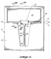
- FIGURES 1 through 4B A preferred embodiment of the accelerometer of the present invention is illustrated in FIGURES 1 through 4B.
- the accelerometer comprises sensing mechanism 12 that is sandwiched between a pair of spacers 14 and 16 that are in turn held between damping plates 20 and 22. Opening 24 in damping plate 22 permits electrical connection between the sensing mechanism and external circuitry.
- the assembled structure is shown in cross section in FIGURE 2.
- the spacers may be provided as separate pieces, as shown, or they may be formed by etching setback regions in the sensing mechanism or the damping plates.
- Sensing mechanism 12 includes support 30 from which proof mass 32 is suspended by two proof mass flexures 34, such that the proof mass can rotate with respect to the support about hinge axis HA that passes through both of flexures 34.
- the cross section of FIGURE 2 is taken through one of proof mass flexures 34.
- the spacing between the outermost end 36 of proof mass 32 and damping plates 20 and 22 defines a pair of gaps 38 that limit the rotational deflection of the proof mass about hinge axis HA.
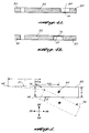
- Dual vibrating beam force transducer 40 is also connected between support 30 and proof mass 32.
- Force transducer 40 includes beams 42 and 44 that extend between interconnecting end portions 46 and 48.
- End portion 46 is connected to and extends from connecting member 50, and the connecting member is joined to proof mass 32 by transducer flexure 52.
- end portion 48 is joined directly to support 30.
- a second transducer flexure could be used to join end portion 48 to the support.
- the function of connecting member 50 is to make transducer flexure 52 as wide as practical, to minimize flexure stress.
- the entire sensing mechanism 12 is a monolithic structure fabricated by etching or chemically milling a wafer of crystalline material, preferably crystalline quartz. Because crystalline quartz is piezoelectric, the use of crystalline quartz permits a relatively straightforward implementation of force transducer 40.
- force transducer 40 may be constructed in the manner set forth in U.S. Patents 4,215,570 and 4,372,173, wherein electrodes are positioned on the surfaces of the beams, and coupled to a suitable drive circuit for causing the beams to oscillate at their resonant frequency. Acceleration in a direction normal to the sensing mechanism causes proof mass 32 to rotate about hinge axis HA, thereby placing a tension or compression force on force transducer 40. The force causes the resonant frequency to change, and measurement of such frequency via the drive circuit thereby provides a measure of the acceleration.
- the thicknesses of support 30, proof mass 32 and force transducer 40 are preferably identical to one another. This is readily achieved by fabricating the sensing mechanism from a single wafer of uniform thickness.
- proof mass flexures 34 are substantially thinner than the support or proof mass, and are formed so that they are contiguous with the lower surface of the sensing mechanism, as viewed in FIGURES 1-4A.
- transducer flexure 52 is substantially thinner than the proof mass or force transducer, and is contiguous with the upper surface of the sensor mechanism. Transducer flexure 52 permits relative rotation of the force transducer with respect to the proof mass about a transducer axis TA that passes through the transducer flexure.
- hinge axis HA and transducer axis TA are preferably offset from one another, as measured along a direction parallel to transducer 40, by an offset distance S. The significance of offset S is described below.
- a significant advantage of the present invention is that it permits the geometry of sensing mechanism 12 to be adjusted so as to significantly reduce the nonlinearities inherent in force-to-frequency transducers, and also permits the implementation of an effective technique for damping proof mass motion.
- FIGURE 5 A conceptual view of the sensing mechanism geometry is set forth in FIGURE 5.
- proof mass 32 is suspended for rotation about hinge axis HA, and has a center of mass 60.
- the sensitive axis SA along which the accelerometer is sensitive to input accelerations is normal to the hinge axis and to the pendulous axis.
- Center of mass 60 is located half way between the upper and lower surface of proof mass 32.
- hinge axis HA is located closer to the lower surface than to the upper surface of the proof mass.
- Force transducer 40 is connected between a first mounting point 62 on the support, and a second mounting point on proof mass 32 at transducer axis TA.
- the thickness of proof mass 32 is t, and a/2 is the distance between hinge axis HA and center of mass 60, measured along pendulous axis PA.
- Force transducer 40 has a longitudinal force sensing axis that is approximately parallel to pendulous axis PA.
- S is the distance between hinge axis HA and transducer axis TA, measured along the pendulous axis, while L is the total length of the force transducer.
- Parameter r is the perpendicular distance between force transducer 40 and hinge axis HA.
- f f0 + k1 F(1-k2F)
- f the vibration frequency
- f0 the zero-acceleration vibration frequency
- k1 the scale factor
- k2 the square law coefficient.
- Examples include single and dual vibrating beam transducers and surface acoustic wave transducers.
- the increase in F with increasing P2, as per Equation (3), can be used to offset the reduction in frequency due to the k2 term in Equation (4).
- N represents the relative contribution of the term k2 to output frequency f at full scale input.
- S Nt2 ⁇ max
- t is equal to .0031 inches (79 ⁇ m)
- ⁇ max is equal to 66 microinches (1.7 ⁇ m)
- N .055
- a suitable value for S would be 0.008 inches (200 ⁇ m). Because of the large lever ratio inherent in the design, only this small offset is required to compensate for 5.5% nonlinearity in the transducer characteristic.
- N a value of 5.5% for a dual vibrating beam transducer whose frequency deviates ⁇ 10% at full scale input.
- ⁇ 10% frequency deviation represents a practical upper limit for transducers of this type.
- Different values of N may be appropriate for different types of transducers, or for dual vibrating beam transducers that are operated at a maximum frequency range of less than ⁇ 10%. Selecting the correct value for S improves linearity by cancelling the dominant second order nonlinearity of the vibrating beam force transducer. In so doing, it greatly improves linearity at high g levels, and also substantially cancels the vibration rectification errors at lower g levels.
- the parameter ⁇ max the angular deflection of the proof mass at full scale input, is defined by the proof mass thickness t and by ⁇ max .
- the minimum size h for gaps 38 (FIGURE 2) is equal to a ⁇ max , where a is the total length of the proof mass along the pendulous axis.
- the parameters a and t define the pendulum width b, while parameters a, b and h define the degree of damping that will be obtained. In practical designs, the damping must be sufficient to prevent a Q value greater than about 10 at resonance.
- the length a of the proof mass along pendulous axis PA must be no greater than half the length of force transducer 40.
- the proof mass length, width and thickness are 0.1, 0.25 and 0.0031 inches (2.5mm, 6.4mm and 79 ⁇ m) respectively, full scale acceleration is 1000g, the value of Q is about 10, and gaps 36 are equal to 0.0031 inches (79 ⁇ m), to provide shock stops at 1500g.
- proof mass 32 are continuous.
- continuous refers to the fact that any straight line path from one edge of the proof mass surface to another will lie entirely within such surface.
- the advantage of having continuous or substantially continuous proof mass surfaces is that the damping that can be obtained from a given surface area is increased, in comparison to noncontinuous surfaces such as that shown in U.K. Patent Application 2,162,314.
Landscapes
- Engineering & Computer Science (AREA)
- Physics & Mathematics (AREA)
- General Physics & Mathematics (AREA)
- General Engineering & Computer Science (AREA)
- Theoretical Computer Science (AREA)
- Computer Hardware Design (AREA)
- Quality & Reliability (AREA)
- Computing Systems (AREA)
- Pressure Sensors (AREA)
- Gyroscopes (AREA)
- Debugging And Monitoring (AREA)
Claims (8)
- Beschleunigungsmesser, ein monolithisches kristallines Substrat enthaltend, mit:
einem Halter (30);
einer Probemasse (32);
wenigstens einen Probemassenbiegeträger (34), der die Probemasse (32) mit dem Halter (30) verbindet, so daß die Probemasse in bezug auf den Halter in Folge einer entlang einer Empfindlichkeitsachse (SA) gerichteten Beschleunigung um eine Gelenkachse (HA) drehbar ist, wobei die Empfindlichkeitsachse (SA) normal zu der Gelenkachse ist; und
einem Kraftaufnehmer (40) mit einer longitudinalen Kraftmessachse, die ungefähr parallel zu einer Pendelachse (PA) liegt, die ihrerseits senkrecht zur Gelenkachse (HA) und zur Empfindlichkeitsachse (SA) steht, wobei der Kraftaufnehmer (40) ein erstes mit dem Halter (30) verbundenes Ende (48) und ein zweites Ende (46) aufweist;
dadurch gekennzeichnet, daß ein Aufnehmerbiegeträger (52) das zweite Ende (46) des Aufnehmers (40) mit der Probemasse (32) verbindet und eine wesentlich geringere Stärke als der Aufnehmer hat, so daß der Aufnehmer (40), wenn sich die Probemasse (32) in bezug auf den Halter (30) dreht, in bezug auf die Probemasse (32) um eine Aufnehmerachse (TA) dreht, die durch den Aufnehmerbiegeträger (52) verläuft und von der Gelenkachse (HA) in einer Richtung entlang der Pendelachse (PA) verschoben ist;
wobei der Kraftaufnehmer (40) durch ein vorbestimmtes Verhältnis zwischen ausgeübter Kraft (F) und Ausgangsfrequenz (f) gekennzeichnet ist, das Verhältnis eine Nichtlinearität zweiter Ordnung enthält und die Verschiebung (S) so gewählt ist, daß es die Nichtlinearität verringert. - Beschleunigungsmesser nach Anspruch 1, wobei der Kraftaufnehmer (40) ferner durch eine maximale partielle Frequenzänderung gekennzeichnet ist und die Verschiebung (S) so ausgewählt ist, daß sie die Nichtlinearität bei der maximalen Frequenzänderung im wesentlichen aufhebt.
- Beschleunigungsmesser nach Anspruch 1 oder 2, bei dem der Halter (30), die Probemasse (32) und der Kraftaufnehmer (40) alle eine gemeinsame Stärke entlang der Empfindlichkeitsachse (SA) aufweisen und alle in einer gemeinsamen Ebene liegen.
- Beschleunigungsmesser nach einem der vorhergehenden Ansprüche, bei dem der Kraftaufnehmer (40) ein Doppelschwingbalken-Kraftaufnehmer ist.
- Beschleunigungsmesser nach Anspruch 4, bei dem der Kraftaufnehmer (40) erste und zweite, sich zwischen den ersten und zweiten Endbereichen (48, 46) erstreckende Balken (42, 44) und ein Verbindungsstück (50) zwischen einem der Endbereiche (46) und dem Aufnehmerbiegeträger (52) aufweist.
- Beschleunigungsmesser nach einem der vorhergehenden Ansprüche, der ferner ober- und unterhalb des Substrats (12) angeordnete erste und zweite Dämpfungsplatten (20, 22) aufweist, wobei die Dämpfungsplatten (20, 22) durch Spalte (38) von der Probemasse (32) beabstandet sind und die Spaltengröße so gewählt ist, daß die Dämpfungsplatten (20, 22) zur Begrenzung der Bewegung der Probemasse (32) in Folge von bereichsüberschreitenden Eingangssignalen fungieren.
- Beschleunigungsmesser nach Anspruch 6, bei dem die Spalte (38) dazu dienen die Vibration der Probemasse (32) zu dämpfen, so daß die Probemasse ein Q von nicht größer als 10 bei Resonanzbedingung hat.
- Beschleunigungsmesser nach einem der vorhergehenden Ansprüche, bei dem die Länge der Probemasse (32) entlang der zur Pendelachse (PA) parallelen Richtung weniger als die halbe Länge des Kraftaufnehmers (40) entlang derselben Richtung ist.
Applications Claiming Priority (2)
| Application Number | Priority Date | Filing Date | Title |
|---|---|---|---|
| US07/377,785 US5274797A (en) | 1986-05-30 | 1989-07-06 | Multiprocessor system with centralized initialization, testing and monitoring of the system and providing centralized timing |
| US544221 | 1995-10-17 |
Publications (3)
| Publication Number | Publication Date |
|---|---|
| EP0441910A1 EP0441910A1 (de) | 1991-08-21 |
| EP0441910A4 EP0441910A4 (en) | 1991-12-04 |
| EP0441910B1 true EP0441910B1 (de) | 1993-12-29 |
Family
ID=23490518
Family Applications (1)
| Application Number | Title | Priority Date | Filing Date |
|---|---|---|---|
| EP90911014A Expired - Lifetime EP0441910B1 (de) | 1989-07-06 | 1990-06-05 | Monolithischer beschleunigungsmesser mit biegsam montiertem kraftwandler |
Country Status (3)
| Country | Link |
|---|---|
| US (1) | US5274797A (de) |
| EP (1) | EP0441910B1 (de) |
| WO (1) | WO1991001009A1 (de) |
Families Citing this family (43)
| Publication number | Priority date | Publication date | Assignee | Title |
|---|---|---|---|---|
| DE3917715A1 (de) * | 1989-05-31 | 1990-12-06 | Teldix Gmbh | Rechnersystem |
| JP2629384B2 (ja) * | 1989-11-16 | 1997-07-09 | 日本電気株式会社 | ダウンラインロード起動制御方式 |
| US5630152A (en) * | 1992-05-18 | 1997-05-13 | Motorola, Inc. | Communication protocol between master and slave device with register information sharing |
| JP3033081B2 (ja) * | 1992-05-21 | 2000-04-17 | 日本電気株式会社 | コンソ−ル接続方式 |
| US6230286B1 (en) * | 1993-01-28 | 2001-05-08 | Siemens Information And Communication Products Llc | Computer system failure reporting mechanism |
| US5325530A (en) * | 1993-01-29 | 1994-06-28 | International Business Machines Corporation | Controller for sequential programming tools executed in a parallel computing environment |
| JPH06274354A (ja) * | 1993-03-12 | 1994-09-30 | Internatl Business Mach Corp <Ibm> | 破壊的なハードウェア動作を制御する方法及びシステム |
| JPH06290079A (ja) * | 1993-03-30 | 1994-10-18 | Hitachi Ltd | 情報処理システム |
| US5561761A (en) * | 1993-03-31 | 1996-10-01 | Ylsi Technology, Inc. | Central processing unit data entering and interrogating device and method therefor |
| US5435000A (en) * | 1993-05-19 | 1995-07-18 | Bull Hn Information Systems Inc. | Central processing unit using dual basic processing units and combined result bus |
| US5440724A (en) * | 1993-06-17 | 1995-08-08 | Bull Hn Information Systems Inc. | Central processing unit using dual basic processing units and combined result bus and incorporating means for obtaining access to internal BPU test signals |
| US5918061A (en) * | 1993-12-29 | 1999-06-29 | Intel Corporation | Enhanced power managing unit (PMU) in a multiprocessor chip |
| US5422806A (en) * | 1994-03-15 | 1995-06-06 | Acc Microelectronics Corporation | Temperature control for a variable frequency CPU |
| JPH07262148A (ja) * | 1994-03-22 | 1995-10-13 | Nec Corp | コンピュータシステム |
| US5537462A (en) * | 1994-04-15 | 1996-07-16 | Aegis Technologies, Inc. | Supervisory interface controller and method for remotely controlled terminal |
| US5631857A (en) * | 1994-06-15 | 1997-05-20 | International Business Machines Corporation | Measuring test tool effectiveness |
| GB2290891B (en) * | 1994-06-29 | 1999-02-17 | Mitsubishi Electric Corp | Multiprocessor system |
| US5625807A (en) * | 1994-09-19 | 1997-04-29 | Advanced Micro Devices | System and method for enabling and disabling a clock run function to control a peripheral bus clock signal |
| US5764928A (en) * | 1994-09-30 | 1998-06-09 | Rosemount Inc. | Microprocessor communication protocol in a multiprocessor transmitter |
| US5642506A (en) * | 1994-12-14 | 1997-06-24 | International Business Machines Corporation | Method and apparatus for initializing a multiprocessor system |
| US5771390A (en) * | 1995-01-05 | 1998-06-23 | Dell Usa, L.P. | System and method for cascading from a power managed suspend state to a suspend-to-disk state in a computer system |
| US5491791A (en) * | 1995-01-13 | 1996-02-13 | International Business Machines Corporation | System and method for remote workstation monitoring within a distributed computing environment |
| US5983357A (en) * | 1995-07-28 | 1999-11-09 | Compaq Computer Corporation | Computer power management |
| US5740353A (en) * | 1995-12-14 | 1998-04-14 | International Business Machines Corporation | Method and apparatus for creating a multiprocessor verification environment |
| US5732281A (en) * | 1996-02-08 | 1998-03-24 | Ncr Corporation | Programmable power management circuit for a power supply in a computer system |
| GB2313931B (en) * | 1996-06-06 | 2000-09-06 | Adrian Richard White | Methods and apparatus for diagnosing and correcting faults in computers |
| US6065078A (en) * | 1997-03-07 | 2000-05-16 | National Semiconductor Corporation | Multi-processor element provided with hardware for software debugging |
| US5930738A (en) * | 1997-10-15 | 1999-07-27 | Mobile Integrated Tecnologies, Inc. | Vehicle computer system environment monitor |
| US6145102A (en) * | 1998-01-20 | 2000-11-07 | Compaq Computer Corporation | Transmission of an error message over a network by a computer which fails a self-test |
| JP3497988B2 (ja) | 1998-04-15 | 2004-02-16 | 株式会社ルネサステクノロジ | 図形処理装置及び図形処理方法 |
| US6754855B1 (en) * | 1999-12-01 | 2004-06-22 | Microsoft Corporation | Automated recovery of computer appliances |
| AU2001255808A1 (en) * | 2000-03-15 | 2001-09-24 | Arc Cores, Inc. | Method and apparatus for debugging programs in a distributed environment |
| US7516334B2 (en) * | 2001-03-22 | 2009-04-07 | Sony Computer Entertainment Inc. | Power management for processing modules |
| KR100421953B1 (ko) * | 2001-07-25 | 2004-03-12 | 엘지전자 주식회사 | 분산형 전송시스템의 제어 유니트간 부트업 프로그램공유장치 및 그 방법 |
| US7007268B2 (en) * | 2001-08-20 | 2006-02-28 | Sun Microsystems, Inc. | Method and apparatus for debugging in a massively parallel processing environment |
| US7385927B2 (en) * | 2002-06-24 | 2008-06-10 | Lsi Logic Corporation | Methods and structure for improved testing of embedded systems |
| US7065688B1 (en) * | 2003-02-19 | 2006-06-20 | Advanced Micro Devices, Inc. | Simultaneous multiprocessor memory testing and initialization |
| US20050228967A1 (en) * | 2004-03-16 | 2005-10-13 | Sony Computer Entertainment Inc. | Methods and apparatus for reducing power dissipation in a multi-processor system |
| US7360102B2 (en) | 2004-03-29 | 2008-04-15 | Sony Computer Entertainment Inc. | Methods and apparatus for achieving thermal management using processor manipulation |
| US8224639B2 (en) * | 2004-03-29 | 2012-07-17 | Sony Computer Entertainment Inc. | Methods and apparatus for achieving thermal management using processing task scheduling |
| JP4277030B2 (ja) * | 2006-06-30 | 2009-06-10 | 株式会社日立製作所 | 通信制御システム |
| US20100058308A1 (en) * | 2008-08-29 | 2010-03-04 | International Business Machines Corporation | Central provider and satellite provider update and diagnosis integration tool |
| DE102010021825A1 (de) * | 2010-05-28 | 2011-12-01 | Christmann Informationstechnik + Medien Gmbh & Co. Kg | Mehrprozessor-Computersystem |
Family Cites Families (27)
| Publication number | Priority date | Publication date | Assignee | Title |
|---|---|---|---|---|
| US4361832A (en) * | 1977-01-28 | 1982-11-30 | Cole Martin T | Automatic centralized monitoring system |
| JPS5856425B2 (ja) * | 1978-10-11 | 1983-12-14 | 横河電機株式会社 | 力変換機構 |
| US4495571A (en) * | 1979-01-31 | 1985-01-22 | Honeywell Information Systems Inc. | Data processing system having synchronous bus wait/retry cycle |
| GB2060225B (en) * | 1979-09-29 | 1983-05-25 | Plessey Co Ltd | Multi-programming data processing system process suspension |
| US4412286A (en) * | 1980-09-25 | 1983-10-25 | Dowd Brendan O | Tightly coupled multiple instruction multiple data computer system |
| FR2497373B1 (fr) * | 1980-12-30 | 1986-09-05 | Bull Sa | Systeme d'alimentation microprogrammable pour systeme de traitement de donnees comportant un panneau de service destine aux operations de maintenance et procedes d'exploitation de ce panneau de service |
| US4445174A (en) * | 1981-03-31 | 1984-04-24 | International Business Machines Corporation | Multiprocessing system including a shared cache |
| US4439839A (en) * | 1981-08-24 | 1984-03-27 | International Telephone And Telegraph Corporation | Dynamically programmable processing element |
| EP0088789B1 (de) * | 1981-09-18 | 1987-08-05 | CHRISTIAN ROVSING A/S af 1984 | Multiprozessor-rechnersystem |
| US4564899A (en) * | 1982-09-28 | 1986-01-14 | Elxsi | I/O Channel bus |
| US4539637A (en) * | 1982-08-26 | 1985-09-03 | At&T Bell Laboratories | Method and apparatus for handling interprocessor calls in a multiprocessor system |
| US4543626A (en) * | 1982-12-06 | 1985-09-24 | Digital Equipment Corporation | Apparatus and method for controlling digital data processing system employing multiple processors |
| US4543628A (en) * | 1983-01-28 | 1985-09-24 | Digital Equipment Corporation | Bus for data processing system with fault cycle operation |
| US4665482A (en) * | 1983-06-13 | 1987-05-12 | Honeywell Information Systems Inc. | Data multiplex control facility |
| FR2549256B1 (fr) * | 1983-06-22 | 1985-11-29 | Philips Ind Commerciale | Procede et machine automatiques pour tester simultanement des systemes informatiques |
| US4641266A (en) * | 1983-11-28 | 1987-02-03 | At&T Bell Laboratories | Access-arbitration scheme |
| US4660141A (en) * | 1983-12-06 | 1987-04-21 | Tri Sigma Corporation | Self configuring computer network with automatic bus exchange of module identification numbers and processor assigned module numbers |
| US4654817A (en) * | 1984-07-27 | 1987-03-31 | Allied Corporation | Real time controller |
| US4677566A (en) * | 1984-10-18 | 1987-06-30 | Burroughs Corporation | Power control network for multiple digital modules |
| US4695946A (en) * | 1984-10-25 | 1987-09-22 | Unisys Corporation | Maintenance subsystem for computer network including power control and remote diagnostic center |
| US4701845A (en) * | 1984-10-25 | 1987-10-20 | Unisys Corporation | User interface processor for computer network with maintenance and programmable interrupt capability |
| US4627060A (en) * | 1984-11-29 | 1986-12-02 | Baxter Travenol Laboratories, Inc. | Watchdog timer |
| US4663539A (en) * | 1984-11-29 | 1987-05-05 | Burroughs Corporation | Local power switching control subsystem |
| US4641238A (en) * | 1984-12-10 | 1987-02-03 | Itt Corporation | Multiprocessor system employing dynamically programmable processing elements controlled by a master processor |
| US4748573A (en) * | 1985-06-28 | 1988-05-31 | Honeywell Inc. | Test management system to acquire, process and display test data |
| US4766768A (en) * | 1987-10-22 | 1988-08-30 | Sundstrand Data Control, Inc. | Accelerometer with isolator for common mode inputs |
| US4881408A (en) * | 1989-02-16 | 1989-11-21 | Sundstrand Data Control, Inc. | Low profile accelerometer |
-
1989
- 1989-07-06 US US07/377,785 patent/US5274797A/en not_active Expired - Lifetime
-
1990
- 1990-06-05 EP EP90911014A patent/EP0441910B1/de not_active Expired - Lifetime
- 1990-06-05 WO PCT/US1990/003201 patent/WO1991001009A1/en not_active Ceased
Also Published As
| Publication number | Publication date |
|---|---|
| EP0441910A4 (en) | 1991-12-04 |
| WO1991001009A1 (en) | 1991-01-24 |
| US5274797A (en) | 1993-12-28 |
| EP0441910A1 (de) | 1991-08-21 |
Similar Documents
| Publication | Publication Date | Title |
|---|---|---|
| EP0441910B1 (de) | Monolithischer beschleunigungsmesser mit biegsam montiertem kraftwandler | |
| US5165279A (en) | Monolithic accelerometer with flexurally mounted force transducer | |
| US4766768A (en) | Accelerometer with isolator for common mode inputs | |
| US5005413A (en) | Accelerometer with coplanar push-pull force transducers | |
| US4872342A (en) | Translational accelerometer and accelerometer assembly method | |
| EP0728311B1 (de) | Doppelpendel beschleunigungsmesser | |
| USRE32931E (en) | Vibratory angular rate sensor system | |
| US4899587A (en) | Method for sensing rotation using vibrating piezoelectric elements | |
| US4881408A (en) | Low profile accelerometer | |
| EP0270664B1 (de) | Temperaturkompensation bei einem beschleunigungsmesser | |
| US6276203B1 (en) | Axis alignment method | |
| US4524619A (en) | Vibratory angular rate sensor system | |
| US6484579B2 (en) | Trim balancing of second-order non-linearity in double ended tuning fork resonators | |
| EP0052318A1 (de) | Kraftaufnehmer | |
| CA2016808A1 (en) | Piezoelectric vibratory rate sensor | |
| US4718275A (en) | Accelerometer with floating beam temperature compensation | |
| US5186053A (en) | Temperature compensated proofmass assembly for accelerometers | |
| EP0273048B1 (de) | Translationsbeschleunigungsmesser | |
| US4706259A (en) | Mounting and isolation system for tuning fork temperature sensor |
Legal Events
| Date | Code | Title | Description |
|---|---|---|---|
| PUAI | Public reference made under article 153(3) epc to a published international application that has entered the european phase |
Free format text: ORIGINAL CODE: 0009012 |
|
| 17P | Request for examination filed |
Effective date: 19910314 |
|
| AK | Designated contracting states |
Kind code of ref document: A1 Designated state(s): CH DE FR GB LI |
|
| A4 | Supplementary search report drawn up and despatched |
Effective date: 19911015 |
|
| AK | Designated contracting states |
Kind code of ref document: A4 Designated state(s): CH DE FR GB LI |
|
| RAP1 | Party data changed (applicant data changed or rights of an application transferred) |
Owner name: SUNDSTRAND CORPORATION |
|
| 17Q | First examination report despatched |
Effective date: 19921204 |
|
| GRAA | (expected) grant |
Free format text: ORIGINAL CODE: 0009210 |
|
| AK | Designated contracting states |
Kind code of ref document: B1 Designated state(s): CH DE FR GB LI |
|
| REF | Corresponds to: |
Ref document number: 69005611 Country of ref document: DE Date of ref document: 19940210 |
|
| ET | Fr: translation filed | ||
| PG25 | Lapsed in a contracting state [announced via postgrant information from national office to epo] |
Ref country code: LI Effective date: 19940630 Ref country code: CH Effective date: 19940630 |
|
| PLBE | No opposition filed within time limit |
Free format text: ORIGINAL CODE: 0009261 |
|
| STAA | Information on the status of an ep patent application or granted ep patent |
Free format text: STATUS: NO OPPOSITION FILED WITHIN TIME LIMIT |
|
| 26N | No opposition filed | ||
| REG | Reference to a national code |
Ref country code: CH Ref legal event code: PL |
|
| REG | Reference to a national code |
Ref country code: GB Ref legal event code: 732E |
|
| REG | Reference to a national code |
Ref country code: GB Ref legal event code: IF02 |
|
| PGFP | Annual fee paid to national office [announced via postgrant information from national office to epo] |
Ref country code: DE Payment date: 20080630 Year of fee payment: 19 |
|
| PGFP | Annual fee paid to national office [announced via postgrant information from national office to epo] |
Ref country code: GB Payment date: 20080506 Year of fee payment: 19 |
|
| GBPC | Gb: european patent ceased through non-payment of renewal fee |
Effective date: 20090605 |
|
| REG | Reference to a national code |
Ref country code: FR Ref legal event code: ST Effective date: 20100226 |
|
| PG25 | Lapsed in a contracting state [announced via postgrant information from national office to epo] |
Ref country code: FR Free format text: LAPSE BECAUSE OF NON-PAYMENT OF DUE FEES Effective date: 20090630 |
|
| PGFP | Annual fee paid to national office [announced via postgrant information from national office to epo] |
Ref country code: FR Payment date: 20080424 Year of fee payment: 19 |
|
| PG25 | Lapsed in a contracting state [announced via postgrant information from national office to epo] |
Ref country code: GB Free format text: LAPSE BECAUSE OF NON-PAYMENT OF DUE FEES Effective date: 20090605 |
|
| PG25 | Lapsed in a contracting state [announced via postgrant information from national office to epo] |
Ref country code: DE Free format text: LAPSE BECAUSE OF NON-PAYMENT OF DUE FEES Effective date: 20100101 |