EP0441853B1 - Method and device for the bimensional localization of neutral particles, particularly for low counting ratios - Google Patents
Method and device for the bimensional localization of neutral particles, particularly for low counting ratios Download PDFInfo
- Publication number
- EP0441853B1 EP0441853B1 EP89912456A EP89912456A EP0441853B1 EP 0441853 B1 EP0441853 B1 EP 0441853B1 EP 89912456 A EP89912456 A EP 89912456A EP 89912456 A EP89912456 A EP 89912456A EP 0441853 B1 EP0441853 B1 EP 0441853B1
- Authority
- EP
- European Patent Office
- Prior art keywords
- converter
- charges
- particles
- plane
- neutral particles
- Prior art date
- Legal status (The legal status is an assumption and is not a legal conclusion. Google has not performed a legal analysis and makes no representation as to the accuracy of the status listed.)
- Expired - Lifetime
Links
- 239000002245 particle Substances 0.000 title claims abstract description 49
- 230000007935 neutral effect Effects 0.000 title claims abstract description 27
- 238000000034 method Methods 0.000 title claims description 13
- 230000004807 localization Effects 0.000 title 1
- 239000011159 matrix material Substances 0.000 claims abstract description 10
- 239000007787 solid Substances 0.000 claims abstract description 9
- 230000004907 flux Effects 0.000 claims abstract description 4
- 238000006243 chemical reaction Methods 0.000 claims description 20
- 230000005684 electric field Effects 0.000 claims description 10
- 239000004020 conductor Substances 0.000 claims description 7
- 239000000463 material Substances 0.000 claims description 7
- XEEYBQQBJWHFJM-UHFFFAOYSA-N Iron Chemical compound [Fe] XEEYBQQBJWHFJM-UHFFFAOYSA-N 0.000 claims description 6
- 229910052688 Gadolinium Inorganic materials 0.000 claims description 4
- UIWYJDYFSGRHKR-UHFFFAOYSA-N gadolinium atom Chemical compound [Gd] UIWYJDYFSGRHKR-UHFFFAOYSA-N 0.000 claims description 4
- 229910052742 iron Inorganic materials 0.000 claims description 3
- 229910052709 silver Inorganic materials 0.000 claims description 3
- 239000004332 silver Substances 0.000 claims description 3
- ZOXJGFHDIHLPTG-UHFFFAOYSA-N Boron Chemical compound [B] ZOXJGFHDIHLPTG-UHFFFAOYSA-N 0.000 claims description 2
- WHXSMMKQMYFTQS-UHFFFAOYSA-N Lithium Chemical compound [Li] WHXSMMKQMYFTQS-UHFFFAOYSA-N 0.000 claims description 2
- 229910052796 boron Inorganic materials 0.000 claims description 2
- 239000003990 capacitor Substances 0.000 claims description 2
- 229910052744 lithium Inorganic materials 0.000 claims description 2
- 230000000638 stimulation Effects 0.000 claims 1
- 238000004141 dimensional analysis Methods 0.000 abstract 1
- 238000003384 imaging method Methods 0.000 abstract 1
- 230000003321 amplification Effects 0.000 description 7
- 238000003199 nucleic acid amplification method Methods 0.000 description 7
- NNPPMTNAJDCUHE-UHFFFAOYSA-N isobutane Chemical compound CC(C)C NNPPMTNAJDCUHE-UHFFFAOYSA-N 0.000 description 4
- 230000001105 regulatory effect Effects 0.000 description 4
- 206010003497 Asphyxia Diseases 0.000 description 2
- CURLTUGMZLYLDI-UHFFFAOYSA-N Carbon dioxide Chemical compound O=C=O CURLTUGMZLYLDI-UHFFFAOYSA-N 0.000 description 2
- RYGMFSIKBFXOCR-UHFFFAOYSA-N Copper Chemical compound [Cu] RYGMFSIKBFXOCR-UHFFFAOYSA-N 0.000 description 2
- 239000000470 constituent Substances 0.000 description 2
- 229910052802 copper Inorganic materials 0.000 description 2
- 239000010949 copper Substances 0.000 description 2
- 230000007547 defect Effects 0.000 description 2
- 238000001514 detection method Methods 0.000 description 2
- 230000000694 effects Effects 0.000 description 2
- 230000006870 function Effects 0.000 description 2
- 150000002500 ions Chemical class 0.000 description 2
- 239000001282 iso-butane Substances 0.000 description 2
- 238000004519 manufacturing process Methods 0.000 description 2
- CRSOQBOWXPBRES-UHFFFAOYSA-N neopentane Chemical compound CC(C)(C)C CRSOQBOWXPBRES-UHFFFAOYSA-N 0.000 description 2
- 238000005457 optimization Methods 0.000 description 2
- 238000010791 quenching Methods 0.000 description 2
- 230000002269 spontaneous effect Effects 0.000 description 2
- 239000000126 substance Substances 0.000 description 2
- 241000251468 Actinopterygii Species 0.000 description 1
- 238000009825 accumulation Methods 0.000 description 1
- 239000000853 adhesive Substances 0.000 description 1
- 230000001070 adhesive effect Effects 0.000 description 1
- 229910002092 carbon dioxide Inorganic materials 0.000 description 1
- 239000001569 carbon dioxide Substances 0.000 description 1
- 230000001419 dependent effect Effects 0.000 description 1
- 230000006866 deterioration Effects 0.000 description 1
- 239000006185 dispersion Substances 0.000 description 1
- 239000003822 epoxy resin Substances 0.000 description 1
- 230000005251 gamma ray Effects 0.000 description 1
- 239000008246 gaseous mixture Substances 0.000 description 1
- 230000010354 integration Effects 0.000 description 1
- 229910052751 metal Inorganic materials 0.000 description 1
- 239000002184 metal Substances 0.000 description 1
- 239000000203 mixture Substances 0.000 description 1
- 238000009206 nuclear medicine Methods 0.000 description 1
- 230000003287 optical effect Effects 0.000 description 1
- 230000003647 oxidation Effects 0.000 description 1
- 238000007254 oxidation reaction Methods 0.000 description 1
- 229920000647 polyepoxide Polymers 0.000 description 1
- 230000000171 quenching effect Effects 0.000 description 1
- 230000005855 radiation Effects 0.000 description 1
- 229910001220 stainless steel Inorganic materials 0.000 description 1
- 239000010935 stainless steel Substances 0.000 description 1
- WFKWXMTUELFFGS-UHFFFAOYSA-N tungsten Chemical compound [W] WFKWXMTUELFFGS-UHFFFAOYSA-N 0.000 description 1
- 229910052721 tungsten Inorganic materials 0.000 description 1
- 239000010937 tungsten Substances 0.000 description 1
- 238000009941 weaving Methods 0.000 description 1
Images

Classifications
-
- H—ELECTRICITY
- H01—ELECTRIC ELEMENTS
- H01J—ELECTRIC DISCHARGE TUBES OR DISCHARGE LAMPS
- H01J47/00—Tubes for determining the presence, intensity, density or energy of radiation or particles
- H01J47/02—Ionisation chambers
-
- H—ELECTRICITY
- H01—ELECTRIC ELEMENTS
- H01J—ELECTRIC DISCHARGE TUBES OR DISCHARGE LAMPS
- H01J47/00—Tubes for determining the presence, intensity, density or energy of radiation or particles
- H01J47/12—Neutron detector tubes, e.g. BF3 tubes
- H01J47/1205—Neutron detector tubes, e.g. BF3 tubes using nuclear reactions of the type (n, alpha) in solid materials, e.g. Boron-10 (n,alpha) Lithium-7, Lithium-6 (n, alpha)Hydrogen-3
- H01J47/1211—Ionisation chambers
Definitions
- the present invention further relates to a method for detecting and locating particles in a stream of neutral particles emitted by a source in such a device.
- the object of the present invention is, on the contrary, to allow the production of higher resolution images and to allow, on a secondary basis, the obtaining of a high contrast, even in a priori unfavorable conditions of irradiation of the object to be examined, and more particularly in the event of poor conversion rates and / or in the presence of fluxes of incident particles of low intensity.
- the device of the invention is essentially characterized in that said conversion elements capable of also ensuring the collection of charges consist of cells distributed in a flat two-dimensional matrix arranged beyond the anode wires with respect to the source .
- the images obtained by the device of the invention have a higher resolution than that of the images obtained by the prior device described in patent EP-A-0 000 271, the two-dimensional matrix of which is formed by two parallel planes. linear elements also parallel to each other, the elements of two different planes being however crossed.
- the converter comprises an insulating plate, one face of which carries said cells, this plate comprising, for each cell, a passage putting this cell in electrical contact with a conductor terminating on the other face of this plate.
- the anode wires are placed in at least one plane substantially parallel to that of the converter, and are substantially parallel to each other.
- the cells comprise a conversion material chosen from the group comprising gadolinium, boron, and lithium, in the case where the particles neutrals used are neutrons and the cells comprise a conversion material chosen from the group comprising iron, and silver in the case where the neutral particles used are X-rays, in particular soft X-rays.
- the gas contains an extinguishing substance present in a proportion of at least 25 percent and that the ratio of the distance "S" between two neighboring anode wires, at the distance "G” between these wires and the converter, ie at least equal to 1.
- At least one of the charge collection elements is connected to a reference electrical potential by means of a capacity capable of accumulating the charges collected by this element.
- the device also comprises a source of voltage capable of creating an electrical voltage between the cathode and the anode wires at least equal to 2000 volts, and the anode wires have a minimum diameter greater than 20 microns.
- the charge amplification operation preferably comprises the application of an electric field of sufficient value to allow the appearance of electronic avalanches of self-regulated size.
- the method can advantageously comprise another operation, consisting in accumulating for a certain time the collected electrical charges.
- the conversion of neutral particles into electrical charges is ensured with a conversion rate such that the number of particles detected is less than 105 particles per second and per square centimeter of surface of the converter.
- FIG. 1 represents in 1 a source of neutral particles, for example a source of soft X-rays, but more typically a source of thermal neutrons in the main applications of the invention.
- a source of neutral particles for example a source of soft X-rays, but more typically a source of thermal neutrons in the main applications of the invention.
- At least part of the flow of particles emitted by this source passes through an object to be examined 2 and reaches the device 3 to which the present invention relates more particularly.
- this device 3 firstly comprises an enclosure, intended to contain a gas and formed of a base 4a and a cover 4b made integral with each other so airtight vis-à-vis the atmosphere, the cover 4b being, however, permeable to neutral particles emitted by the source 1, to neutrons for example.
- the gas contained in the enclosure is a gaseous mixture allowing the appearance of a "streamer" operating mode, in other words the appearance of avalanches of electrons whose size is self-regulated by spontaneous suffocation.
- this gas comprises an effective quenching substance, consisting of carbonaceous and polyatomic molecules comprising many relaxation modes, such as isobutane or neopentane, in proportion of at least 25 percent.
- this gas can be a mixture of 50 percent carbon dioxide and 50 percent isobutane, subjected to a pressure of the order of one to five bars.
- the converter 5 and the planar grid are connected to a reference electrical potential, and are for example brought to potentials close to the earth potential prevailing outside the enclosure, both playing the role. cathodes.
- the wires of the planar network 6 are on the other hand connected to an external source of electrical potential which delivers a positive potential + V with respect to the average potentials of the converter 5 and of the grid 7, for example of the order of 2000 to 7000 volts.
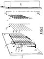
- the converter 5 comprises an insulating plate 8, better visible in FIG. 3, and a two-dimensional matrix of cells, such as 9a, 9b, 9c, arranged on one face of the plate 8.
- Each of the cells such as 9a, is intended to supply a signal representing a point of a two-dimensional image of the object 2.
- Each of the cells therefore operates independently of its neighbors, and the image obtained consists of a matrix of points each of which corresponds to one of these cells.
- the light intensity associated with a point of the image depends on the quantity of particles received by the corresponding cell, this quantity being itself dependent on the thickness and the nature of the material of which the object is made. solid angle defined by the source on the one hand and by the cell in question on the other.
- the wavy path T1 represents that of a neutral particle, a neutron for example, which, after having been emitted by the source 1 and passed through the object 2, the cover 4b of the detector, the grid 7 and the plane of wires 6, reaches a cell 9c of the converter 5.
- cell 9c made of an adequate material, emits in a statistically observable and reproducible way a fast electron whose trajectory is represented in T2.
- this fast electron causes the ionization of the gas on its path, and the electrons thus produced drift towards the nearest wire, for example 6c, of the network 6 under the effect of the electric field resulting from the difference between the potentials of the converter 5 and of the wire plane 6.
- This movement is identified by the arrows such as T3 in FIG. 3.
- this amplification corresponds to a mode of operation in which avalanches of electrons appear whose size is self-regulated.
- the corresponding positive ions representing a number of charges equal to that of the charges of all the electrons created, move away from the wire 6c from which they are repelled because of their charge, and drift towards the nearest cathodes, constituted by the grid 7 on the one hand and by the converter 5 on the other hand.
- the converter 5 has a layered structure supported by an insulating plate 8, the latter being for example formed by a printed circuit board made of epoxy resin, with a thickness of 3.2 millimeters.
- This plate is covered with a layer of copper 10, a few microns thick.
- a layer of conductive adhesive 11 On the copper layer 10 is deposited a layer of conductive adhesive 11, with which the assembly can be covered with a layer of a conversion material 12, for example a sheet of gadolinium, with a thickness of tenth of a micron, previously gilded to avoid oxidation.
- a conversion material 12 for example a sheet of gadolinium, with a thickness of tenth of a micron, previously gilded to avoid oxidation.
- This stack of layers 10, 11, and 12, deposited on at least the major part of the surface of the plate 8, is then cut, by saw cutter lines such as 13 attacking the upper face of this plate, into elements. electrically isolated from each other, which constitute cells 9a, 9b, 9c, etc.
- the insulating plate 8 comprises, for each cell such as 9c, a passage such as 14c putting this cell in electrical contact with a conductor such as 15c ending on the other face of the plate 8.
- each wire such as 6c is stretched exactly over a row of cells such as 9c, these advantageously having a rectangular or square shape.
- the cathode grid 7 may consist of stainless steel wires with a diameter of 50 microns each, intersecting at right angles, in a pitch of 500 microns, the role of this grid being to allow a symmetrization of the electric field on the wires such as 6c.
- the plane of wires 6 is produced in the form of a weaving on an insulating frame of golden tungsten wires with a minimum diameter of at least 20 microns, and preferably from 50 to 100 microns each, arranged parallel to one another. others following a pitch S of 2.54 millimeters for example. All of the wires are connected to a source of electrical potential outside the enclosure 3, delivering a voltage of 5000 volts for example.
- the distance G between the plane of wires 6 and the converter 5 on the one hand and the distance between the plane of wires 6 and the grid 7 on the other hand are preferably equal and of the order of 3 to 5 millimeters.
- the cells such as 9c for example have the shape of squares of 2 millimeters on a side, produced at the same pace as the wires, 2.54 millimeters in this case.
- the conversion material 12 used in cells such as 9c advantageously consists of gadolinium in the case where the neutral particles emitted by the source 1 are thermal neutrons, and of iron or silver in the case where these particles are rays X, in particular soft X.
- the conductors such as 15c are on the one hand connected to the earth potential via respective capacitors such as 16c, on the other hand connected, each at least for a given time interval, to an electronic device 17, of the type known per se, the function of which is to convert the signal present on each of these conductors to a point in a video image and / or to information capable of being stored in an optical, electronic or other memory.
- the wires such as 6c play the role of means for amplification and collection of negative charges, while the converter and its cells play both the role of conversion means, of cathode, and of means of collection of positive charges.
- the useful signal for each point of the image of the object, is constituted by the electrical signal present on the conductors such as 15c, the cells such as 9c constitute more precisely the useful elements of the means of charge collection.
- the invention develops all its advantages when the number of neutral particles detected is less than 105 particles per second and per square centimeter of surface of the converter, and it is of particular interest when the particles detected are thermal neutrons.
- the charge amplification operation includes the application of an electric field of sufficient value to allow the appearance of electron avalanches of self-regulated size (streamer mode), and it is advantageous , for this purpose, that the ratio of the distance S (FIG. 3) between two neighboring anode wires 6b, 6c, to the distance G between these wires and the cathode 12, is at least equal to 1.
- this mode allows the creation, for each fast electron emitted by the converter, of an extremely high number of charges, typically of the order of 107 to 109, so that it is possible, even from a small number of particles received by the converter, or a small number of particles converted by it, to obtain an image of an irradiated object such as 2 ( Figure 1).
- This property is also best exploited according to the embodiment of the invention which comprises an accumulation, for a certain time, of the collected electrical charges, in a capacity such as 16c.
- this operating mode makes it possible to overcome an intrinsic defect which the solid converters exhibit under certain conditions of use, in particular for the detection of thermal neutrons.
- the fast electrons from the solid converter have a very high energy dispersion.
- the number of first ionization charges directly created per unit of distance by a fast electron passing through the gas is a rapidly variable function of the energy of this fast electron, so that the charge collecting elements, the cells such as 9c in this case, risk providing respective signals representative no longer of the number of neutral particles that these elements have received, but of the energy of the fast electrons to which these particles have led by conversion.
- the "streamer" mode which has the property of amplifying charges in a highly non-linear manner, makes it possible to re-establish this defect by giving rise, for each fast electron, to a number of charges collected which is substantially independent of the number of charges of first ionization directly created by fast electrons.
- the use of this operating mode thus makes it possible to reduce the fluctuations of the useful signal to a level close to the fish fluctuations of the source.
Landscapes
- Physics & Mathematics (AREA)
- Chemical & Material Sciences (AREA)
- Engineering & Computer Science (AREA)
- Chemical Kinetics & Catalysis (AREA)
- High Energy & Nuclear Physics (AREA)
- Materials Engineering (AREA)
- Measurement Of Radiation (AREA)
- Analysing Materials By The Use Of Radiation (AREA)
Abstract
Description
La présente invention concerne notamment un dispositif pour la détection et la localisation de particules dans un flux de particules neutres émises par une source, comprenant:
- un convertisseur solide sensiblement plan, propre, sous l'impact de ces particules neutres, à produire des charges électriques, ce convertisseur comprenant des éléments de conversion électriquement autonomes les uns par rapport aux autres;
- des fils anodiques, destinés à être portés à un potentiel électrique différent de celui du convertisseur pour faire apparaître un champ électrique, et à produire une amplification des charges par ionisation d'un gaz environnant, stimulée par ce champ électrique;
- des moyens de collectage de charges, comprenant des éléments conducteurs électriquement autonomes les uns par rapport aux autres, dont certains au moins constituent des éléments de conversion; et,
- une enceinte perméable aux particules neutres, renfermant le convertisseur, les fils anodiques, les moyens de collectage des charges, et le gaz.
- a solid converter substantially planar, clean, under the impact of these neutral particles, to produce electric charges, this converter comprising conversion elements electrically autonomous with respect to each other;
- anode wires, intended to be brought to an electric potential different from that of the converter to reveal an electric field, and to produce an amplification of the charges by ionization of a surrounding gas, stimulated by this electric field;
- charge collection means, comprising electrically autonomous conductive elements with respect to one another, at least some of which constitute conversion elements; and,
- an enclosure permeable to neutral particles, containing the converter, the anode wires, the charge collection means, and the gas.
La présente invention concerne en outre un procédé pour détecter et localiser des particules dans un flux de particules neutres émises par une source dans un tel dispositif.The present invention further relates to a method for detecting and locating particles in a stream of neutral particles emitted by a source in such a device.
Un dispositif de ce type est décrit dans la demande de brevet européen publiée sous le numéro Ep-A-0 000 271.A device of this type is described in the European patent application published under the number Ep-A-0 000 271.
Bien que ce dispositif antérieur permette la réalisation directe d'images bidimensionnelles, sa conception repose sur la recherche d'une optimisation de l'efficacité dans certaines applications particulières au détriment d'une optimisation de la résolution.Although this prior device allows direct production of two-dimensional images, its design is based on the search for an optimization of the efficiency in certain particular applications to the detriment of an optimization of the resolution.
Un autre exemple de dispositif de l'art antérieur figure dans le document publié dans la revue Nuclear Instruments and Methods, Volume 156, n°1, Octobre 1978 et intitulé "A hybrid MWPC gamma ray detecting system for applications in nuclear medicine", pages 27-31, de J.E. Bateman et al. Ce document décrit un empilement de compteurs proportionnels multifils dans lequel les cathodes sont constituées de feuilles métalliques convertissant les rayons gammas incidents en électrons et les anodes sont constituées de nappes de fils parallèles entre eux. Des rainures parallèles entre elles sont formées à la surface des cathodes, ces rainures étant alternativement perpendiculaires à la direction des fils anodiques.Another example of a device of the prior art appears in the document published in the journal Nuclear Instruments and Methods, Volume 156, n ° 1, October 1978 and entitled "A hybrid MWPC gamma ray detecting system for applications in nuclear medicine", pages 27-31, of JE Bateman et al. This document describes a stack of multi-wire proportional counters in which the cathodes consist of metal sheets converting the incident gamma rays into electrons and the anodes consist of layers of wires parallel to each other. Parallel grooves between them are formed on the surface of the cathodes, these grooves being alternately perpendicular to the direction of the anode wires.
Le but de la présente invention est au contraire de permettre la réalisation d'images de résolution supérieure et de permettre, à titre secondaire, l'obtention d'un haut contraste, même dans des conditions a priori défavorables d'irradiation de l'objet à examiner, et plus particulièrement en cas de taux de conversion médiocres et/ou en présence de flux de particules incidentes de faible intensité.The object of the present invention is, on the contrary, to allow the production of higher resolution images and to allow, on a secondary basis, the obtaining of a high contrast, even in a priori unfavorable conditions of irradiation of the object to be examined, and more particularly in the event of poor conversion rates and / or in the presence of fluxes of incident particles of low intensity.
A cette fin, le dispositif de l'invention, est essentiellement caractérisé en ce que lesdits éléments de conversion propres à assurer également le collectage de charges sont constitués de cellules réparties suivant une matrice bidimensionnelle plane disposée au delà des fils anodiques par rapport à la source.To this end, the device of the invention is essentially characterized in that said conversion elements capable of also ensuring the collection of charges consist of cells distributed in a flat two-dimensional matrix arranged beyond the anode wires with respect to the source .
Grâce à cette disposition, les images obtenues par le dispositif de l'invention ont une résolution supérieure à celle des images obtenues par le dispositif antérieur décrit dans le brevet EP-A-0 000 271, dont la matrice bidimensionnelle est formée par deux plans parallèles d'éléments linéaires également parallèles les uns aux autres, les éléments de deux plans différents étant cependant croisés.Thanks to this arrangement, the images obtained by the device of the invention have a higher resolution than that of the images obtained by the prior device described in patent EP-A-0 000 271, the two-dimensional matrix of which is formed by two parallel planes. linear elements also parallel to each other, the elements of two different planes being however crossed.
En effet cette disposition antérieure, en raison de l'espacement des deux plans qui forment ensemble la matrice bidimensionnelle, et de l'erreur de parallaxe qui en résulte, introduit pour tout rayonnement non perpendiculaire à la matrice des déformations différentes des images partielles récupérées sur les deux plans, dont résulte une altération sensible de la résolution.Indeed, this previous arrangement, due to the spacing of the two planes which together form the two-dimensional matrix, and the resulting parallax error, introduced for any radiation not perpendicular to the matrix, different deformations of the partial images recovered on the two planes, which results in a significant deterioration in resolution.
Selon un mode de réalisation avantageux de l'invention, le convertisseur comprend une plaque isolante dont une face porte lesdites cellules, cette plaque comportant, pour chaque cellule, une traversée mettant cette cellule en contact électrique avec un conducteur aboutissant sur l'autre face de cette plaque.According to an advantageous embodiment of the invention, the converter comprises an insulating plate, one face of which carries said cells, this plate comprising, for each cell, a passage putting this cell in electrical contact with a conductor terminating on the other face of this plate.
Selon une disposition en soit connue, il est préférable pour l'invention que les fils anodiques soient disposés dans au moins un plan sensiblement parallèle à celui du convertisseur, et soient sensiblement parallèles les uns aux autres.According to a known arrangement, it is preferable for the invention that the anode wires are placed in at least one plane substantially parallel to that of the converter, and are substantially parallel to each other.
Compte tenu de la disposition adoptée dans l'invention, il est préférable, pour obtenir une bonne efficacité, que les cellules comprennent un matériau de conversion choisi dans le groupe comprenant le gadolinium, le bore, et le lithium, dans le cas où les particules neutres utilisées sont des neutrons et que les cellules comprennent un matériau de conversion choisi dans le groupe comprenant le fer, et l'argent dans le cas où les particules neutres utilisées sont des rayons X, en particulier des X mous.In view of the arrangement adopted in the invention, it is preferable, in order to obtain good efficiency, that the cells comprise a conversion material chosen from the group comprising gadolinium, boron, and lithium, in the case where the particles neutrals used are neutrons and the cells comprise a conversion material chosen from the group comprising iron, and silver in the case where the neutral particles used are X-rays, in particular soft X-rays.
Dans les cas où, quelqu'en soit la cause, le taux de comptage des particules est faible, il est avantageux que le gaz contienne une substance d'extinction présente dans une proportion d'au moins 25 pourcent et que le rapport de la distance "S" entre deux fils anodiques voisins, à la distance "G" entre ces fils et le convertisseur, soit au moins égal à 1.In cases where, whatever the cause, the particle count rate is low, it is advantageous that the gas contains an extinguishing substance present in a proportion of at least 25 percent and that the ratio of the distance "S" between two neighboring anode wires, at the distance "G" between these wires and the converter, ie at least equal to 1.
Ces caractéristiques autorisent le dispositif à fonctionner selon un mode connu de l'homme de l'art sous la dénomination anglo-saxonne de "self-quenching streamer mode", caractérisé par l'apparition d'avalanches électroniques s'empilant jusqu'à une taille critique du nuage de charges, pour laquelle elles s'étouffent.These characteristics allow the device to operate according to a mode known to those skilled in the art under the Anglo-Saxon designation of "self-quenching streamer mode", characterized by the appearance of electronic avalanches stacking up to a critical size of the cloud of charges, for which they suffocate.
Les avantages particuliers, que ce mode de fonctionnement par ailleurs connu développe dans l'application spécifique qu'en fait l'invention, seront mieux compris dans la description détaillée de celle-ci.The particular advantages, which this otherwise known mode of operation develops in the specific application which the invention makes of it, will be better understood in the detailed description thereof.
De préférence, l'un au moins des éléments de collectage de charges est relié à un potentiel électrique de référence par l'intermédiaire d'une capacité propre à accumuler les charges collectées par cet élément.Preferably, at least one of the charge collection elements is connected to a reference electrical potential by means of a capacity capable of accumulating the charges collected by this element.
Une telle intégration des charges contribue à compenser les effets négatifs associés aux flux de particules à faible taux de comptage.Such an integration of the charges contributes to compensating for the negative effects associated with the flow of particles with a low counting rate.
De préférence, le dispositif comprend aussi une source de tension propre à créer entre la cathode et les fils anodiques une tension électrique au moins égale à 2000 volts, et les fils anodiques ont un diamètre minimum supérieur à 20 microns.Preferably, the device also comprises a source of voltage capable of creating an electrical voltage between the cathode and the anode wires at least equal to 2000 volts, and the anode wires have a minimum diameter greater than 20 microns.
L'invention concerne aussi un procédé pour détecter et localiser des particules dans un flux de particules neutres émises par une source dans un tel dispositif, comprenant les opérations consistant à:
- recevoir ces particules sur un convertisseur solide sensiblement plan, et produire ainsi des charges électriques à partir de ces particules neutres;
- amplifier ces charges par ionisation stimulée d'un gaz environnant; et
- collecter, sur le convertisseur, en différents emplacements espacés les uns des autres, les charges présentes dans au moins un plan sensiblement parallèle au convertisseur; ce procédé étant principalement caractérisé en ce que lesdits emplacements constituent une matrice bidimensionnelle plane.
- receiving these particles on a substantially planar solid converter, and thus producing electric charges from these neutral particles;
- amplify these charges by stimulated ionization of a surrounding gas; and
- collecting, on the converter, at different locations spaced from each other, the charges present in at least one plane substantially parallel to the converter; this process being mainly characterized in that said locations constitute a planar two-dimensional matrix.
Dans le cas de faibles taux de comptage, l'opération d'amplification de charges comprend de préférence l'application d'un champ électrique de valeur suffisante pour permettre l'apparition d'avalanches électroniques à taille auto-régulée.In the case of low counting rates, the charge amplification operation preferably comprises the application of an electric field of sufficient value to allow the appearance of electronic avalanches of self-regulated size.
Le procédé peut avantageusement comprendre une autre opération, consistant à accumuler pendant un certain temps les charges électriques collectées.The method can advantageously comprise another operation, consisting in accumulating for a certain time the collected electrical charges.
De préférence, la conversion des particules neutres en charges électriques est assurée avec un taux de conversion tel que le nombre de particules détectées est inférieur à 10⁵ particules par seconde et par centimètre carré de surface du convertisseur.Preferably, the conversion of neutral particles into electrical charges is ensured with a conversion rate such that the number of particles detected is less than 10⁵ particles per second and per square centimeter of surface of the converter.
Ce procédé est particulièrement adapté, pour des raisons qui seront détaillées dans la suite de la description, à l'utilisation de neutrons thermiques en tant que particules neutres.This process is particularly suitable, for reasons which will be detailed in the following description, for the use of thermal neutrons as neutral particles.
D'autres caractéristiques et avantages de l'invention ressortiront clairement de la description qui en est faite ci-après, à titre indicatif et nullement limitatif, en référence aux dessins annexés, parmi lesquels:
- la figure 1 est une vue schématique représentant, en perspective, la mise en oeuvre d'un dispositif conforme à l'invention;
- la figure 2 est une vue schématique éclatée d'un dispositif conforme à l'invention; et
- la figure 3 est une vue en coupe d'un dispositif de détection utilisable dans le système de la figure 1, faite suivant le plan III-III de la figure 2;
- Figure 1 is a schematic view showing, in perspective, the implementation of a device according to the invention;
- Figure 2 is an exploded schematic view of a device according to the invention; and
- Figure 3 is a sectional view of a detection device usable in the system of Figure 1, taken along the plane III-III of Figure 2;
La figure 1 représente en 1 une source de particules neutres, par exemple une source de rayons X mous, mais plus typiquement une source de neutrons thermiques dans les applications principales de l'invention.FIG. 1 represents in 1 a source of neutral particles, for example a source of soft X-rays, but more typically a source of thermal neutrons in the main applications of the invention.
Une partie au moins du flux de particules émis par cette source traverse un objet à examiner 2 et parvient au dispositif 3 sur lequel porte plus particulièrement la présente invention.At least part of the flow of particles emitted by this source passes through an object to be examined 2 and reaches the device 3 to which the present invention relates more particularly.
Comme le montre plus en détail la figure 2, ce dispositif 3 comprend tout d'abord une enceinte, destinée à renfermer un gaz et formée d'une embase 4a et d'un couvercle 4b rendus solidaires l'un de l'autre de façon étanche vis-à-vis de l'atmosphère, le couvercle 4b étant en revanche perméable aux particules neutres émises par la source 1, aux neutrons par exemple.As shown in more detail in FIG. 2, this device 3 firstly comprises an enclosure, intended to contain a gas and formed of a
Le gaz contenu dans l'enceinte est un mélange gazeux autorisant l'apparition d'un mode de fonctionnement "streamer", autrement dit l'apparition d'avalanches d'électrons dont la taille est auto-régulée par étouffement spontané.The gas contained in the enclosure is a gaseous mixture allowing the appearance of a "streamer" operating mode, in other words the appearance of avalanches of electrons whose size is self-regulated by spontaneous suffocation.
A cette fin, ce gaz comprend une substance d'extinction (quencher) efficace, constituée de molécules carbonées et polyatomiques comportant de nombreux modes de relaxation, tel que l'isobutane ou le néopentane, en proportion d'au moins 25 pourcent.To this end, this gas comprises an effective quenching substance, consisting of carbonaceous and polyatomic molecules comprising many relaxation modes, such as isobutane or neopentane, in proportion of at least 25 percent.
Par exemple, ce gaz peut être un mélange de 50 pourcent de gaz carbonique et de 50 pourcent d'isobutane, soumis à une pression de l'ordre de un à cinq bars.For example, this gas can be a mixture of 50 percent carbon dioxide and 50 percent isobutane, subjected to a pressure of the order of one to five bars.
A l'intérieur de l'enceinte, et parallèlement à l'embase 4a sont disposés:
- un convertisseur solide sensiblement
plan 5, propre, sous l'impact de ces particules neutres, à produire des charges électriques; - un réseau plan 6 de fils conducteurs tels que 6a, 6b, disposé parallèlement au convertisseur et à distance de celui-ci;
- et, de préférence, une grille plane de
fils conducteurs 7, elle-même disposée à distance du réseau 6.
- a solid converter substantially plane 5, clean, under the impact of these neutral particles, to produce electric charges;
- a flat network 6 of conductive wires such as 6a, 6b, arranged parallel to the converter and at a distance therefrom;
- and preferably a flat grid of
conductive wires 7, itself arranged at a distance from the network 6.
Le convertisseur 5 et la grille plane sont reliés à un potentiel électrique de référence, et sont par exemple portés à des potentiels voisins du potentiel de la terre régnant à l'extérieur de l'enceinte, l'un et l'autre jouant le rôle de cathodes.The
Les fils du réseau plan 6 sont en revanche reliés à une source externe de potentiel électrique qui délivre un potentiel positif + V par rapport aux potentiels moyens du convertisseur 5 et de la grille 7, par exemple de l'ordre de 2000 à 7000 volts.The wires of the planar network 6 are on the other hand connected to an external source of electrical potential which delivers a positive potential + V with respect to the average potentials of the
Le convertisseur 5 comprend une plaque isolante 8, mieux visible sur la figure 3, et une matrice bidimensionnelle de cellules, telles que 9a, 9b, 9c, disposées sur une face de la plaque 8.The
Chacune des cellules, telles que 9a, est destinée à fournir un signal représentant un point d'une image bidimensionnelle de l'objet 2.Each of the cells, such as 9a, is intended to supply a signal representing a point of a two-dimensional image of the object 2.
Chacune des cellules fonctionne donc indépendamment de ses voisines, et l'image obtenue est constituée d'une matrice de points dont chacun correspond à l'une de ces cellules.Each of the cells therefore operates independently of its neighbors, and the image obtained consists of a matrix of points each of which corresponds to one of these cells.
L'intensité lumineuse associée à un point de l'image dépend de la quantité de particules reçues par la cellule correspondante, cette quantité étant elle-même dépendante de l'épaisseur et de la nature du matériau dont est fait l'objet dans l'angle solide délimité par la source d'une part et par la cellule en question d'autre part.The light intensity associated with a point of the image depends on the quantity of particles received by the corresponding cell, this quantity being itself dependent on the thickness and the nature of the material of which the object is made. solid angle defined by the source on the one hand and by the cell in question on the other.
Le fonctionnement du dispositif est illustré sur la figure 3.The operation of the device is illustrated in Figure 3.
Le trajet ondulé T1 représente celui d'une particule neutre, un neutron par exemple, qui, après avoir été émise par la source 1 et traversé l'objet 2, le couvercle 4b du détecteur, la grille 7 et le plan de fils 6, atteint une cellule 9c du convertisseur 5.The wavy path T1 represents that of a neutral particle, a neutron for example, which, after having been emitted by the source 1 and passed through the object 2, the
Frappée par cette particule neutre, la cellule 9c, constituée d'un matériau adéquat, émet de façon statistiquement observable et reproductible un électron rapide dont la trajectoire est représentée en T2.Struck by this neutral particle,
En traversant l'enceinte, cet électron rapide provoque l'ionisation du gaz sur son parcours, et les électrons ainsi produits dérivent vers le fil le plus proche, par exemple 6c, du réseau 6 sous l'effet du champ électrique résultant de la différence entre les potentiels du convertisseur 5 et du plan de fils 6. Ce mouvement est repéré par les flèches telles que T3 sur la figure 3.By crossing the enclosure, this fast electron causes the ionization of the gas on its path, and the electrons thus produced drift towards the nearest wire, for example 6c, of the network 6 under the effect of the electric field resulting from the difference between the potentials of the
Parvenus à quelques diamètres du fil 6c, ces électrons sont très violemment accélérés par le champ électrique, dont la valeur augmente considérablement au voisinage immédiat du fil.Having reached a few diameters of the
Ils acquièrent alors suffisamment d'énergie pour ioniser le gaz à leur tour, provoquant ainsi une amplification électronique.They then acquire enough energy to ionize the gas in turn, thus causing electronic amplification.
Selon une caractéristique de l'invention, cette amplification correspond à un mode de fonctionnement dans lequel apparaissent des avalanches d'électrons dont la taille est auto-régulée.According to a characteristic of the invention, this amplification corresponds to a mode of operation in which avalanches of electrons appear whose size is self-regulated.
Ce phénomène, dont résulte une augmentation considérable de la charge électrique, représentée par le nombre final d'électrons produit par chaque électron rapide, se poursuit jusqu'à étouffement spontané des avalanches.This phenomenon, which results in a considerable increase in the electric charge, represented by the final number of electrons produced by each fast electron, continues until spontaneous suffocation of the avalanches.
Les ions positifs correspondants, représentant un nombre de charges égal à celui des charges de l'ensemble des électrons créés, s'écartent du fil 6c dont ils sont repoussés en raison de leur charge, et dérivent vers les cathodes les plus proches, constituées par la grille 7 d'une part et par le convertisseur 5 d'autre part.The corresponding positive ions, representing a number of charges equal to that of the charges of all the electrons created, move away from the
Les ions positifs créés du côté de la grille sont recueillis par cette dernière tandis que ceux créés du côté du convertisseur 5 sont recueillis par une cellule de celui-ci, la cellule 9c en l'occurrence. Leur mouvement est repéré sur la figure 3 par les flèches en pointillé T4.The positive ions created on the side of the grid are collected by the latter while those created on the side of the
Comme le montre la figure 3, le convertisseur 5 présente une structure en couches supportée par une plaque isolante 8, cette dernière étant par exemple contituée par une carte de circuit imprimé en résine époxy, d'une épaisseur de 3.2 millimètres.As shown in FIG. 3, the
La surface supérieure de cette plaque est recouverte d'une couche de cuivre 10, de quelques microns d'épaisseur.The upper surface of this plate is covered with a layer of
Sur la couche de cuivre 10 est déposée une couche de colle conductrice 11, grâce à laquelle l'ensemble peut être recouvert d'une couche d'un matériau de conversion 12, par exemple une feuille de gadolinium, d'une épaisseur d'un dixième de micron, préalablement dorée pour en éviter l'oxydation.On the
Cet empilage de couches 10, 11, et 12, déposé sur la plus grande partie au moins de la surface de la plaque 8, est ensuite découpé, par des traits de fraise scie tels que 13 attaquant la face supérieure de cette plaque, en éléments électriquement isolés les uns des autres, qui constituent les cellules 9a, 9b, 9c, etc.This stack of
De plus, la plaque isolante 8 comporte, pour chaque cellule telle que 9c, une traversée telle que 14c mettant cette cellule en contact électrique avec un conducteur tel que 15c aboutissant sur l'autre face de la plaque 8.In addition, the insulating plate 8 comprises, for each cell such as 9c, a passage such as 14c putting this cell in electrical contact with a conductor such as 15c ending on the other face of the plate 8.
De préférence, chaque fil tel que 6c est tendu exactement au-dessus d'une rangée de cellules telles que 9c, celles-ci ayant avantageusement une forme rectangulaire ou carrée.Preferably, each wire such as 6c is stretched exactly over a row of cells such as 9c, these advantageously having a rectangular or square shape.
A titre d'exemple, la grille cathodique 7 peut être constituée de fils d'acier inoxydable d'un diamètre de 50 microns chacun, s'entrecroisant à angle droit, suivant un pas de 500 microns, le rôle de cette grille étant de permettre une symétrisation du champ électrique sur les fils tels que 6c.By way of example, the
Le plan de fils 6 est réalisé sous la forme d'un tissage sur un cadre isolant de fils de tungstène dorés d'un diamètre minimum d'au moins 20 microns, et de préférence de 50 à 100 microns chacun, disposés parallèlement les uns aux autres suivant un pas S de 2.54 millimètres par exemple. L'ensemble des fils est relié à une source de potentiel électrique extérieur à l'enceinte 3, délivrant une tension de 5000 volts par exemple.The plane of wires 6 is produced in the form of a weaving on an insulating frame of golden tungsten wires with a minimum diameter of at least 20 microns, and preferably from 50 to 100 microns each, arranged parallel to one another. others following a pitch S of 2.54 millimeters for example. All of the wires are connected to a source of electrical potential outside the enclosure 3, delivering a voltage of 5000 volts for example.
La distance G entre le plan de fils 6 et le convertisseur 5 d'une part et la distance entre le plan de fils 6 et la grille 7 d'autre part sont de préférence égales et de l'ordre de 3 à 5 millimètres.The distance G between the plane of wires 6 and the
Les cellules telles que 9c ont par exemple la forme de carrés de 2 millimètres de côté, réalisés au même pas que les fils, 2.54 millimètres en l'occurence.The cells such as 9c for example have the shape of squares of 2 millimeters on a side, produced at the same pace as the wires, 2.54 millimeters in this case.
Le matériau de conversion 12 utilisé dans les cellules telles que 9c est avantageusement constitué de gadolinium dans le cas où les particules neutres émises par la source 1 sont des neutrons thermiques, et de fer ou d'argent dans le cas où ces particules sont des rayons X, en particulier des X mous.The
Les conducteurs tels que 15c sont d'une part reliés au potentiel de terre par l'intermédiaire de capacités respectives telles que 16c, d'autre part reliés, chacun au moins pendant un intervalle de temps donné, à un dispositif électronique 17, de type connu en soi, dont la fonction est de convertir le signal présent sur chacun de ces conducteurs en un point d'une image vidéo et/ou en une information susceptible d'être stockée dans une mémoire optique, électronique, ou autre.The conductors such as 15c are on the one hand connected to the earth potential via respective capacitors such as 16c, on the other hand connected, each at least for a given time interval, to an
Dans les conditions exposées, les fils tels que 6c jouent le rôle de moyens d'amplification et de collectage de charges négatives, tandis que le convertisseur et ses cellules jouent à la fois le rôle de moyens de conversion, de cathode, et de moyens de collectage de charges positives.Under the conditions set out, the wires such as 6c play the role of means for amplification and collection of negative charges, while the converter and its cells play both the role of conversion means, of cathode, and of means of collection of positive charges.
En fait, dans la mesure où le signal utile, pour chaque point de l'image de l'objet, est constitué par le signal électrique présent sur les conducteurs tels que 15c, les cellules telles que 9c constituent plus précisément les éléments utiles des moyens de collectage de charges.In fact, insofar as the useful signal, for each point of the image of the object, is constituted by the electrical signal present on the conductors such as 15c, the cells such as 9c constitute more precisely the useful elements of the means of charge collection.
L'invention développe tous ses avantages lorsque le nombre de particules neutres détectées est inférieur à 10⁵ particules par seconde et par centimètre carré de surface du convertisseur, et elle revêt un intérêt particulier lorsque les particules détectées sont des neutrons thermiques.The invention develops all its advantages when the number of neutral particles detected is less than 10⁵ particles per second and per square centimeter of surface of the converter, and it is of particular interest when the particles detected are thermal neutrons.
Comme mentionné plus haut, l'opération d'amplification de charges comprend l'application d'un champ électrique de valeur suffisante pour permettre l'apparition d'avalanches d'électrons à taille auto-régulée (streamer mode), et il est avantageux, à cette fin, que le rapport de la distance S (figure 3) entre deux fils anodiques voisins 6b, 6c, à la distance G entre ces fils et la cathode 12, soit au moins égal à 1.As mentioned above, the charge amplification operation includes the application of an electric field of sufficient value to allow the appearance of electron avalanches of self-regulated size (streamer mode), and it is advantageous , for this purpose, that the ratio of the distance S (FIG. 3) between two neighboring
L'intérêt du mode de fonctionnement "streamer" pour un détecteur appliqué à l'imagerie conformément à l'invention trouve son origine dans les deux raisons suivantes.The interest of the "streamer" operating mode for a detector applied to imagery according to the invention has its origin in the following two reasons.
D'une part, ce mode permet la création, pour chaque électron rapide émis par le convertisseur, d'un nombre de charges extrêmement élevé, typiquement de l'ordre de 10⁷ à 10⁹, de sorte qu'il est possible, même à partir d'un petit nombre de particules reçues par le convertisseur, ou d'un petit nombre de particules converties par lui, d'obtenir une image d'un objet irradié tel que 2 (figure 1). Cette propriété est en outre exploitée au mieux selon le mode de réalisation de l'invention qui comprend une accumulation, pendant un certain temps, des charges électriques collectées, dans une capacité telle que 16c.On the one hand, this mode allows the creation, for each fast electron emitted by the converter, of an extremely high number of charges, typically of the order of 10⁷ to 10⁹, so that it is possible, even from a small number of particles received by the converter, or a small number of particles converted by it, to obtain an image of an irradiated object such as 2 (Figure 1). This property is also best exploited according to the embodiment of the invention which comprises an accumulation, for a certain time, of the collected electrical charges, in a capacity such as 16c.
D'autre part et surtout, ce mode de fonctionnement permet de pallier un défaut intrinsèque que présentent les convertisseurs solides dans certaines conditions d'utilisation, notamment pour la détection de neutrons thermiques.On the other hand and above all, this operating mode makes it possible to overcome an intrinsic defect which the solid converters exhibit under certain conditions of use, in particular for the detection of thermal neutrons.
En effet, si le nombre d'électrons rapides créés à partir d'un nombre prédéterminé de neutrons incidents est constant, statistiquement au moins, en revanche les électrons rapides issus du convertisseur solide présentent une très grande dispersion énergétique.Indeed, if the number of fast electrons created from a predetermined number of incident neutrons is constant, statistically at least, on the other hand the fast electrons from the solid converter have a very high energy dispersion.
Or, le nombre de charges de première ionisation directement créées par unité de distance par un électron rapide traversant le gaz est une fonction rapidement variable de l'énergie de cet électron rapide, de sorte que les éléments de collectage de charges, les cellules telles que 9c en l'occurrence, risquent de fournir des signaux respectifs représentatifs non plus du nombre de particules neutres que ces éléments ont reçues, mais de l'énergie des électrons rapides auxquels ces particules ont conduit par conversion.However, the number of first ionization charges directly created per unit of distance by a fast electron passing through the gas is a rapidly variable function of the energy of this fast electron, so that the charge collecting elements, the cells such as 9c in this case, risk providing respective signals representative no longer of the number of neutral particles that these elements have received, but of the energy of the fast electrons to which these particles have led by conversion.
Le mode "streamer", qui a la propriété d'amplifier les charges de façon fortement non linéaire, permet de rétablir ce défaut en donnant naissance, pour chaque électron rapide, à un nombre de charges collectées qui est sensiblement indépendant du nombre de charges de première ionisation directement créées par les électrons rapides. L'utilisation de ce mode de fonctionnement permet ainsi de ramener les fluctuations du signal utile à un niveau proche des fluctuations poissonniennes de la source.The "streamer" mode, which has the property of amplifying charges in a highly non-linear manner, makes it possible to re-establish this defect by giving rise, for each fast electron, to a number of charges collected which is substantially independent of the number of charges of first ionization directly created by fast electrons. The use of this operating mode thus makes it possible to reduce the fluctuations of the useful signal to a level close to the fish fluctuations of the source.
Claims (14)
- A device for detecting and locating particles in a flux of neutral particles emitted by a source (1), the device comprising:
a substantially plane solid converter (5) suitable for producing electrical charges under the impact of said neutral charges, the converter comprising conversion elements (9a, 9b, 9c) which are electrically independent from one another;
anode wires (6a, 6b) for raising to an electric potential different from that of the converter to cause an electric field to appear, and for amplifying charges by ionizing a surrounding gas under stimulation from said electric field;
charge collecting means (9c, 15c) comprising conductor elements that are electrically independent from one another, with at least some of them constituting conversion elements; and
an enclosure (4a, 4b) permeable to the neutral particles and containing the converter, the anode wires, the charge collecting means, and the gas;
the device being characterized in that said conversion elements also suitable for collecting charge are constituted by cells distributed over a plane two-dimensional matrix disposed on the opposite side of the anode wires to the source. - A device according to claim 1, characterized in that the converter comprises an insulating plate (8) having one face carrying said cells, said plate including, for each cell, a through hole (14c) putting said cell into electrical contact with a conductor (15c) leading to the other face of said plate.
- A device according to any preceding claim, characterized in that said anode wires are disposed in at least one plane (6) substantially parallel to the plane of the converter, and are substantially parallel to one another.
- A device according to any preceding claim, characterized in that said cells comprise a conversion material selected from the group comprising: gadolinium, boron, and lithium.
- A device according to any preceding claim, characterized in that said cells comprise a conversion meterial selected from the group comprising: iron and silver.
- A device according to any preceding claim in combination with claim 3, characterized in that the gas contains a quencher constituting not less than 25% thereof, and in that the ratio of the distance (S) between two adjacent anode wires (6b 6c) to the distance (G) between these wires and the converter (5) is not less than 1.
- A device according to claim 6, characterized in that at least one of said charge collecting elements is connected to a reference electrical potential via a capacitor (16c) suitable for accumulating the charge collected by said element.
- A device according to any preceding claim, characterized in that it includes a voltage source suitable for establishing an electrical potential of not less than 2,000 volts between the cathode and the anode wires.
- A device according to any preceding claim, characterized in that the anode wires (6a, 6b, 6c) have a minimum diameter of not less than 20 microns.
- A method of detecting and locating particles in a flux of neutral particles emitted by a source (1) in a device according to any preceding claim, comprising the operations consisting in:
receiving said particles on a substantially plane solid converter (5), thereby producing electrical charges from said neutral particles;
amplifying said charges by stimulated icnization of a surrounding gas; and
collecting the charges present in at least one plane substantially parallel to the converter on the converter at different locations that are spaced apart from one another;
the method being characterized in that said locations constitute a plane two-dimensional matrix. - A method according to claim 10, characterized in that the operation of amplifying the charges comprises applying an electric field of sufficient value to enable electron avalanches of self-regulating size to appear.
- A method according to claim 10 or 11, characterized in that it further includes an operation consisting in accumulating the collected electrical charge over a certain length of time.
- A method according to any one of claims 10 to 12, characterized in that the particles are converted into electrical charges with a conversion rate such that the number of detected particles is less than 10⁵ particles per second and per square centimeter of converter area.
- A method according to any one of claims 10 to 13, characterized in that the neutral particles essentially comprise thermal neutrons.
Applications Claiming Priority (5)
| Application Number | Priority Date | Filing Date | Title |
|---|---|---|---|
| FR8814186A FR2638536B1 (en) | 1988-10-28 | 1988-10-28 | METHOD AND DEVICE FOR LOCATING NEUTRAL PARTICLES FOR LOW COUNTING RATES |
| FR8814187A FR2638567B1 (en) | 1988-10-28 | 1988-10-28 | METHOD AND DEVICE FOR TWO-DIMENSIONAL LOCATION OF NEUTRAL PARTICLES |
| FR8814186 | 1988-10-28 | ||
| FR8814187 | 1988-10-28 | ||
| PCT/FR1989/000553 WO1990004851A1 (en) | 1988-10-28 | 1989-10-24 | Method and device for the bidimensional localization of neutral particles, particularly for low counting ratios |
Publications (2)
| Publication Number | Publication Date |
|---|---|
| EP0441853A1 EP0441853A1 (en) | 1991-08-21 |
| EP0441853B1 true EP0441853B1 (en) | 1994-10-12 |
Family
ID=26226960
Family Applications (1)
| Application Number | Title | Priority Date | Filing Date |
|---|---|---|---|
| EP89912456A Expired - Lifetime EP0441853B1 (en) | 1988-10-28 | 1989-10-24 | Method and device for the bimensional localization of neutral particles, particularly for low counting ratios |
Country Status (5)
| Country | Link |
|---|---|
| US (1) | US5087821A (en) |
| EP (1) | EP0441853B1 (en) |
| AT (1) | ATE112891T1 (en) |
| DE (1) | DE68918871T2 (en) |
| WO (1) | WO1990004851A1 (en) |
Families Citing this family (5)
| Publication number | Priority date | Publication date | Assignee | Title |
|---|---|---|---|---|
| US6037597A (en) * | 1997-02-18 | 2000-03-14 | Neutech Systems, Inc. | Non-destructive detection systems and methods |
| US7377356B2 (en) * | 2004-05-25 | 2008-05-27 | Ford Global Technologies, Llc | Driver selectable steering ratios |
| US8704189B2 (en) * | 2009-11-18 | 2014-04-22 | Saint-Gobain Ceramics & Plastics, Inc. | System and method for ionizing radiation detection |
| US8319175B2 (en) * | 2010-08-31 | 2012-11-27 | Schlumberger Technology Corporation | Nano-tips based gas ionization chamber for neutron detection |
| CN104345333B (en) * | 2013-08-07 | 2017-02-22 | 清华大学 | Array combination device for combining neutron detection tubes and neutron detection equipment |
Family Cites Families (3)
| Publication number | Priority date | Publication date | Assignee | Title |
|---|---|---|---|---|
| GB1583571A (en) * | 1977-06-24 | 1981-01-28 | Exxon Research Engineering Co | Hydrocarbon synthesis from co and h2 with ru ni or rh supported on a titanium oxide |
| FR2591036A1 (en) * | 1985-12-04 | 1987-06-05 | Balteau | DEVICE FOR DETECTING AND LOCATING NEUTRAL PARTICLES, AND APPLICATIONS |
| GB8606086D0 (en) * | 1986-03-12 | 1986-04-16 | Marsden P K | Cathode/converter |
-
1989
- 1989-10-24 EP EP89912456A patent/EP0441853B1/en not_active Expired - Lifetime
- 1989-10-24 AT AT89912456T patent/ATE112891T1/en active
- 1989-10-24 WO PCT/FR1989/000553 patent/WO1990004851A1/en active IP Right Grant
- 1989-10-24 DE DE68918871T patent/DE68918871T2/en not_active Expired - Fee Related
- 1989-10-24 US US07/678,279 patent/US5087821A/en not_active Expired - Fee Related
Also Published As
| Publication number | Publication date |
|---|---|
| WO1990004851A1 (en) | 1990-05-03 |
| DE68918871D1 (en) | 1994-11-17 |
| ATE112891T1 (en) | 1994-10-15 |
| US5087821A (en) | 1992-02-11 |
| EP0441853A1 (en) | 1991-08-21 |
| DE68918871T2 (en) | 1995-04-27 |
Similar Documents
| Publication | Publication Date | Title |
|---|---|---|
| EP0855086B1 (en) | High-resolution position detector for high-flux ionising particle streams | |
| EP0742954B1 (en) | Ionising radiation detector having proportional microcounters | |
| US7589327B2 (en) | Energy sensitive direct conversion radiation detector | |
| JPH08509550A (en) | Radiation detector | |
| EP0810631A1 (en) | High resolution radiographic imaging device | |
| EP0228933B1 (en) | Neutral particles detection and situating device, and its use | |
| US8586936B2 (en) | Hybrid anode for semiconductor radiation detectors | |
| FR2951580A1 (en) | RADIOGRAPHIC IMAGING DEVICE AND DETECTOR FOR A RADIOGRAPHIC IMAGING DEVICE | |
| EP0441853B1 (en) | Method and device for the bimensional localization of neutral particles, particularly for low counting ratios | |
| EP0730291B1 (en) | Ionizing X-ray or low dosis gamma medical imaging devices | |
| FR2790100A1 (en) | Two-dimensional ionizing radiation detector, especially X-ray, gamma photon, proton, neutron or muon detector, comprises conversion material block with fluid medium filled slits producing easily processed particles | |
| EP0851512A1 (en) | High resistivity semiconductor ionizing radiation detector | |
| EP0064913A2 (en) | X-rays multidetector | |
| EP0045704B1 (en) | Radiation detector | |
| EP0368694A1 (en) | Process and device for the high-resolution localisation of neutral particles | |
| AU2001296123B2 (en) | Gaseous-based detector for ionizing radiation and method in manufacturing the same | |
| EP1410420A1 (en) | Ionising radiation detector with solid radiation conversion plate, and method for making same | |
| FR2705791A1 (en) | X-ray detector for obtaining selective energy responses | |
| EP2483909B1 (en) | Radiation detectors and autoradiographic imaging devices comprising such detectors | |
| US20060033029A1 (en) | Low-voltage, solid-state, ionizing-radiation detector | |
| JP2000121738A (en) | Semiconductor radiation detector | |
| FR2638536A1 (en) | Method and device for locating neutral particles under low counting rates | |
| FR2638567A1 (en) | Method and device for two-dimensional locating of neutral particles | |
| JP4397685B2 (en) | Semiconductor detector | |
| FR2974186A1 (en) | DEVICE FOR MEASURING THE CHARACTERISTICS OF AN X-RAY BEAM |
Legal Events
| Date | Code | Title | Description |
|---|---|---|---|
| PUAI | Public reference made under article 153(3) epc to a published international application that has entered the european phase |
Free format text: ORIGINAL CODE: 0009012 |
|
| 17P | Request for examination filed |
Effective date: 19910321 |
|
| AK | Designated contracting states |
Kind code of ref document: A1 Designated state(s): AT BE CH DE FR GB IT LI LU NL SE |
|
| 17Q | First examination report despatched |
Effective date: 19930712 |
|
| GRAA | (expected) grant |
Free format text: ORIGINAL CODE: 0009210 |
|
| AK | Designated contracting states |
Kind code of ref document: B1 Designated state(s): AT BE CH DE FR GB IT LI LU NL SE |
|
| REF | Corresponds to: |
Ref document number: 112891 Country of ref document: AT Date of ref document: 19941015 Kind code of ref document: T |
|
| REF | Corresponds to: |
Ref document number: 68918871 Country of ref document: DE Date of ref document: 19941117 |
|
| ITF | It: translation for a ep patent filed | ||
| EAL | Se: european patent in force in sweden |
Ref document number: 89912456.4 |
|
| GBT | Gb: translation of ep patent filed (gb section 77(6)(a)/1977) |
Effective date: 19950106 |
|
| PLBE | No opposition filed within time limit |
Free format text: ORIGINAL CODE: 0009261 |
|
| STAA | Information on the status of an ep patent application or granted ep patent |
Free format text: STATUS: NO OPPOSITION FILED WITHIN TIME LIMIT |
|
| PGFP | Annual fee paid to national office [announced via postgrant information from national office to epo] |
Ref country code: LU Payment date: 19951001 Year of fee payment: 7 |
|
| 26N | No opposition filed | ||
| PGFP | Annual fee paid to national office [announced via postgrant information from national office to epo] |
Ref country code: GB Payment date: 19951020 Year of fee payment: 7 |
|
| PGFP | Annual fee paid to national office [announced via postgrant information from national office to epo] |
Ref country code: SE Payment date: 19951025 Year of fee payment: 7 |
|
| PGFP | Annual fee paid to national office [announced via postgrant information from national office to epo] |
Ref country code: FR Payment date: 19951030 Year of fee payment: 7 Ref country code: AT Payment date: 19951030 Year of fee payment: 7 |
|
| PGFP | Annual fee paid to national office [announced via postgrant information from national office to epo] |
Ref country code: NL Payment date: 19951031 Year of fee payment: 7 |
|
| PGFP | Annual fee paid to national office [announced via postgrant information from national office to epo] |
Ref country code: CH Payment date: 19951114 Year of fee payment: 7 |
|
| PGFP | Annual fee paid to national office [announced via postgrant information from national office to epo] |
Ref country code: BE Payment date: 19951116 Year of fee payment: 7 |
|
| PGFP | Annual fee paid to national office [announced via postgrant information from national office to epo] |
Ref country code: DE Payment date: 19951219 Year of fee payment: 7 |
|
| PG25 | Lapsed in a contracting state [announced via postgrant information from national office to epo] |
Ref country code: LU Free format text: LAPSE BECAUSE OF NON-PAYMENT OF DUE FEES Effective date: 19961024 Ref country code: GB Effective date: 19961024 Ref country code: AT Effective date: 19961024 |
|
| PG25 | Lapsed in a contracting state [announced via postgrant information from national office to epo] |
Ref country code: SE Effective date: 19961025 |
|
| PG25 | Lapsed in a contracting state [announced via postgrant information from national office to epo] |
Ref country code: LI Effective date: 19961031 Ref country code: CH Effective date: 19961031 Ref country code: BE Effective date: 19961031 |
|
| BERE | Be: lapsed |
Owner name: SCHLUMBERGER INDUSTRIES Effective date: 19961031 |
|
| PG25 | Lapsed in a contracting state [announced via postgrant information from national office to epo] |
Ref country code: NL Effective date: 19970501 |
|
| GBPC | Gb: european patent ceased through non-payment of renewal fee |
Effective date: 19961024 |
|
| REG | Reference to a national code |
Ref country code: CH Ref legal event code: PL |
|
| PG25 | Lapsed in a contracting state [announced via postgrant information from national office to epo] |
Ref country code: FR Effective date: 19970630 |
|
| NLV4 | Nl: lapsed or anulled due to non-payment of the annual fee |
Effective date: 19970501 |
|
| PG25 | Lapsed in a contracting state [announced via postgrant information from national office to epo] |
Ref country code: DE Effective date: 19970701 |
|
| EUG | Se: european patent has lapsed |
Ref document number: 89912456.4 |
|
| REG | Reference to a national code |
Ref country code: FR Ref legal event code: ST |
|
| PG25 | Lapsed in a contracting state [announced via postgrant information from national office to epo] |
Ref country code: IT Free format text: LAPSE BECAUSE OF NON-PAYMENT OF DUE FEES;WARNING: LAPSES OF ITALIAN PATENTS WITH EFFECTIVE DATE BEFORE 2007 MAY HAVE OCCURRED AT ANY TIME BEFORE 2007. THE CORRECT EFFECTIVE DATE MAY BE DIFFERENT FROM THE ONE RECORDED. Effective date: 20051024 |