EP0045704B1 - Radiation detector - Google Patents
Radiation detector Download PDFInfo
- Publication number
- EP0045704B1 EP0045704B1 EP81401366A EP81401366A EP0045704B1 EP 0045704 B1 EP0045704 B1 EP 0045704B1 EP 81401366 A EP81401366 A EP 81401366A EP 81401366 A EP81401366 A EP 81401366A EP 0045704 B1 EP0045704 B1 EP 0045704B1
- Authority
- EP
- European Patent Office
- Prior art keywords
- plates
- electrodes
- bars
- radiation
- brought
- Prior art date
- Legal status (The legal status is an assumption and is not a legal conclusion. Google has not performed a legal analysis and makes no representation as to the accuracy of the status listed.)
- Expired
Links
- 230000005855 radiation Effects 0.000 title claims description 20
- 239000004020 conductor Substances 0.000 description 10
- 230000005684 electric field Effects 0.000 description 9
- 238000001514 detection method Methods 0.000 description 8
- 239000012212 insulator Substances 0.000 description 8
- 229910052751 metal Inorganic materials 0.000 description 5
- 239000002184 metal Substances 0.000 description 5
- 238000009413 insulation Methods 0.000 description 4
- 238000003325 tomography Methods 0.000 description 4
- 150000002500 ions Chemical class 0.000 description 3
- 230000003071 parasitic effect Effects 0.000 description 3
- 239000000919 ceramic Substances 0.000 description 2
- 230000000694 effects Effects 0.000 description 2
- 239000003822 epoxy resin Substances 0.000 description 2
- 230000003993 interaction Effects 0.000 description 2
- 239000000463 material Substances 0.000 description 2
- 239000000615 nonconductor Substances 0.000 description 2
- 210000000056 organ Anatomy 0.000 description 2
- 230000010287 polarization Effects 0.000 description 2
- 229920000647 polyepoxide Polymers 0.000 description 2
- 229920005989 resin Polymers 0.000 description 2
- 239000011347 resin Substances 0.000 description 2
- 238000005070 sampling Methods 0.000 description 2
- 230000035945 sensitivity Effects 0.000 description 2
- BQCADISMDOOEFD-UHFFFAOYSA-N Silver Chemical compound [Ag] BQCADISMDOOEFD-UHFFFAOYSA-N 0.000 description 1
- 238000010521 absorption reaction Methods 0.000 description 1
- 238000010276 construction Methods 0.000 description 1
- 238000010586 diagram Methods 0.000 description 1
- 238000009792 diffusion process Methods 0.000 description 1
- 229910052500 inorganic mineral Inorganic materials 0.000 description 1
- 239000011707 mineral Substances 0.000 description 1
- 238000000465 moulding Methods 0.000 description 1
- 239000003973 paint Substances 0.000 description 1
- 239000002245 particle Substances 0.000 description 1
- 230000002688 persistence Effects 0.000 description 1
- 230000006798 recombination Effects 0.000 description 1
- 238000005215 recombination Methods 0.000 description 1
- 230000003252 repetitive effect Effects 0.000 description 1
- 229910052709 silver Inorganic materials 0.000 description 1
- 239000004332 silver Substances 0.000 description 1
- WFKWXMTUELFFGS-UHFFFAOYSA-N tungsten Chemical compound [W] WFKWXMTUELFFGS-UHFFFAOYSA-N 0.000 description 1
- 229910052721 tungsten Inorganic materials 0.000 description 1
- 239000010937 tungsten Substances 0.000 description 1
- 229910052724 xenon Inorganic materials 0.000 description 1
- FHNFHKCVQCLJFQ-UHFFFAOYSA-N xenon atom Chemical compound [Xe] FHNFHKCVQCLJFQ-UHFFFAOYSA-N 0.000 description 1
Images


Classifications
-
- H—ELECTRICITY
- H01—ELECTRIC ELEMENTS
- H01J—ELECTRIC DISCHARGE TUBES OR DISCHARGE LAMPS
- H01J47/00—Tubes for determining the presence, intensity, density or energy of radiation or particles
- H01J47/02—Ionisation chambers
-
- G—PHYSICS
- G01—MEASURING; TESTING
- G01T—MEASUREMENT OF NUCLEAR OR X-RADIATION
- G01T1/00—Measuring X-radiation, gamma radiation, corpuscular radiation, or cosmic radiation
- G01T1/29—Measurement performed on radiation beams, e.g. position or section of the beam; Measurement of spatial distribution of radiation
- G01T1/2914—Measurement of spatial distribution of radiation
- G01T1/2921—Static instruments for imaging the distribution of radioactivity in one or two dimensions; Radio-isotope cameras
- G01T1/2935—Static instruments for imaging the distribution of radioactivity in one or two dimensions; Radio-isotope cameras using ionisation detectors
Definitions
- the present invention relates to a radiation detector and in particular for X-ray tomographies.
- this invention applies to multicell detectors containing a high pressure gas and intended for use in tomographic systems, comprising a computer for example.
- an X-ray tomography device comprising a calculator
- the spatial distribution of the intensities of the X-rays having passed through the object to be viewed according to the cutting plane and according to different paths, is translated into electrical signals which are processed to allow the obtaining an image of this object.
- the detectors used must detect electromagnetic energy, with sufficient spatial resolution.
- the sampling speed of the signal supplied by the detectors is generally limited by the relaxation time of these detectors. It is therefore necessary to use detectors having short relaxation times, high sensitivity and very good spatial resolution.
- a multicellular type detector comprising a plurality of spatially separated cells, makes it possible to produce an economic and effective tomography apparatus.
- X-radiation is detected in a gas of high atomic mass under high pressure.
- the X photons interact with the gas to produce ion-electron pairs.
- the electrons are collected on electrodes, under the effect of an electric field applied between the electrodes and provide electric currents proportional to the intensity of the X-rays.
- These electrons are collected on plates or positive electrodes alternating with plates or positive electrodes alternating with negative plates or electrodes from which the ions are collected.
- the electrons and positive ions which are produced by the interaction of X photons and gas move along the lines of force of the electric field, and are collected on the positive and negative electrodes. All of the charges produced by the interaction of X-rays with the gas must be collected in as short a time as possible, and above all in the most uniform time possible in the volume of the detection cell, so that the signal corresponding to the next sampling interval, is not disturbed.
- the positive and negative electrodes are separated by insulators which, unfortunately, have a very high sensitivity to X-rays, which leads to significant parasitic conduction phenomena. This drawback is aggravated by the fact that these phenomena are not quantitatively repetitive and that they exhibit considerable persistence after irradiation.
- the need to increase the spatial resolution to improve the quality of the image obtained requires the construction of detectors having a very large number of cells.
- the oldest tomography devices presented approximately 200 detection cells arranged in a fan at an angle of 40 °.
- Patent US-A 3396275 further describes a device for conventional detection of incident radiation of random direction - of the type comprising a first plurality of juxtaposed polarization electrodes constituted by circular plates brought to the same potential, between which a second plurality are interposed circular plates interconnected with each other to form a single detection electrode brought to a different potential - in which the periphery of said circular polarization plates is provided with raised annular lips which surround the periphery of the corresponding circular detection plates, so as to maintain a high electric field in the vicinity of these edges, in order to reduce the recombination of the particles and thus improve the temperature stability of said device.
- the object of the present invention is to remedy the above-mentioned drawbacks and in particular to produce a radiation detector making it possible to prevent any ionization behind the electrodes, and thus to avoid any appearance of parasitic drag phenomenon.
- the device according to the invention makes it possible to increase the rigidity of the electrodes and thus to avoid any parasitic phenomenon of microphony.
- the subject of the invention is a radiation detector comprising an ionization chamber filled with a given gas and, in this chamber, juxtaposed and separate electrodes, formed of successive plates of generally rectangular shape placed opposite one another and parallel to the direction of the incident radiation to be detected, these plates being intended to be brought to potentials such that two successive plates are respectively brought to a first and a second potential, these plates being supported, at two of their opposite ends parallel to the direction of the incident radiation to be detected, by insulating bars, characterized in that each plate comprises, at its end opposite to that closest to the incident radiation to be detected, an edge record arranged so as to intercept the radiation at the end of its path in the detector, thus preventing any ionization behind the volume separating two successive plates.
- a radiation detector according to the invention.
- This detector comprises a multicellular ionization chamber comprising a plurality of electrodes in the form of plates joined alternately to two sources of potential; each cell includes an electrode and electrodes located on either side; gas is contained in the volumes formed between these electrodes.
- the ionization chamber which is not shown in detail in the figure, can be filled with xenon under pressure, in the case where the R radiation is X radiation. All the electrodes 2 are brought to a first positive potential for example , so as to constitute anodes; the electrodes 3 can be brought to a second zero or negative potential for example, to form cathodes.
- All the electrodes 2 and all the electrodes 3 are carried at their high and low ends by insulating bars; on the side of the low end of the electrodes, these insulating bars are shown in 5, 6, 7, 8. On the side of the high end, these insulating bars are shown schematically in 9.
- the plates which constitute the electrodes form baffles such as 10, 11, 12, 13 ...
- baffles such as 10, 11, 12, 13 ...
- These baffles are intended to protect the bars against X-rays which can be emitted towards the insulation of these strips and which could cause leakage currents in this insulation.
- Each plate, opposite the side which receives the R radiation, has a raised edge 15. This raised edge makes it possible to prevent the incident X-rays which are not entirely stopped by the gas between the electrodes from striking the bottom of the ionization chamber.
- the number of insulating bars which support the electrodes has been limited to four in the figure, to simplify the representation. These bars are partially sectioned on one face 15, facing the corresponding sides 16 of the plates, so as to support these plates and to separate them, by insulating sections. Each of the bars is covered with a conductive deposit 19, on a face opposite to the face 15, located opposite the plates. This metallic deposit also partially covers the sides 17, 18 of the bars, adjacent to the face of the bar covered by the conductive deposit 16.
- the ends 16, 20, 21, 22 ... of the plates, located near the bars are cut out so that the bar 6, for example, supports all the plates 2 brought to the same first positive potential 23 and an adjacent bar such as 5 supports all the plates 3, brought to the second negative potential 24.
- the bar 8 supports all the plates 2 brought to the first positive potential 23.
- the metal deposits such as 17, 18, 19 which cover the bars are brought to the same potential as that of the plates supported by the bars corresponding.
- the metal deposit 17, 18, 19 covering the bar 5 and the metal deposit covering the bar 7 are brought to the same potential as that of the corresponding plates 3, c ' that is to say at the second potential 24.
- the metal deposits covering the bars 6, 8 are brought to the same potential as that of the plates 2, that is to say to the potential 23.
- each plate is correctly fixed on the bars and is isolated from the next plate.
- the metal deposits which cover each of the bars to reduce leakage currents in the insulation of the bars. This reduction results from the presence of the metallic conductive deposit which creates a guard ring system, near the end of each of the bars.
- Baffles such as 10, 11, 12, 13 have a V-shaped profile; this V is protruding on one face of each plate and returning on the other face, so that the top 25 of the V protruding on a plate, engages in the base 26 of the V returning from the next plate in order to completely obstruct the interval between the two plates.
- Means 27 capable of collecting and processing the signals coming from the different electrodes have also been shown in non-detailed manner; these signals make it possible to visualize the section of an organ situated in front of the detector and which is crossed by the X-rays; after partial absorption by the organ, X-rays strike the detector.
- the means 27 which allow this display are well known in the state of the art and have not been shown in detail.
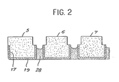
- Figure 2 is a cross section of the bars supporting the plates at one of their ends.
- the various insulating bars are made integral by means of insulating layers of epoxy resin, such as layer 28. These layers of resin have a level which is lower than the edge of the conductive deposits 17, 18 so that the resin is not in contact with the insulating bars 5, 6, 7 and 8.
- the mounting of the detector can be carried out as follows; each of the bars is covered with conductive deposits 17, 18, 19 constituted for example by a silver paint, then the different bars are made integral thanks to the layers 28 of epoxy resin. Finally, the bars are partially sectioned by grooves such as 29, then the different correctly cut plates are placed on the high and low supports thus produced by this assembly of grooved bars.
- FIG. 3 there is shown one of the baffles 10 of the plate 2 for example.
- This baffle has the profile of a V-shaped molding and extends in the direction of the radiation R, parallel to the plane formed by the faces of the bars which support the plates.
- X-rays which do not follow the path of the incident rays R can be emitted in the direction R 1 ' towards the bar 9 supporting the electrodes. This emission can result either from a diffusion of certain rays in the gas contained in the chamber, or from a fluorescence of the detection gas.
- the X-rays scattered in the gas are very few, but have a high energy.
- fluorescence X-rays are very numerous but their energy is low.
- FIG. 4 is an illustration of the operating principle of a guard ring, in the field of electrostatics. It is assumed in this figure that a central conductor 30 is brought to a potential + V with respect to a reference potential; this central conductor is surrounded by another conductor 31 brought to the potential + V with respect to the reference potential; the reference potential is that of the external mass 32, assumed to be brought to the 0 volt potential.
- the coaxial conductor 31 is isolated from the central conductor 30; this coaxial conductor plays the role of guard ring for the central conductor since the electric field E ⁇ between this central conductor and the guard ring is zero; in fact, the central conductor and the coaxial conductor are brought to the same potential with respect to the reference potential of the external mass and a non-zero electric field only appears outside the guard ring, between this ring and the external mass 32. It follows from this principle that, if one refers to FIG. 1, the conductive layer 19, brought to the same potential as that of the electrode supported by the corresponding strip, plays the role of guard ring for this electrode. The electric field is therefore zero between the electrodes 3, carried by the strip 5 and the conductive layer 19, in the embodiment shown in FIG. 1.
- the electric field is zero between the conductive layer covering the strip 6 and the electrodes 2, between the conductive layer covering the strip 7 and the electrodes 3, and between the conductive layer covering the strip 8 and the electrodes 2.
- the insulating bars can be produced in ceramic bars which are excellent electrical insulators, dimensionally very stable and easily machinable with conventional tools.
- the electrodes are preferably made of a dense material having a high atomic number, so as to constitute a good X-ray screen between each cell. This material can for example be tungsten.
- the detector which has just been described, it is possible to achieve the goals mentioned above, that is to say to avoid any leakage current in the insulators supporting the electrodes, to avoid any dragging phenomenon behind the electrodes, to ensure good mechanical rigidity of these electrodes and thus, to produce a detector having 500 and even 1000 detection cells at an angle of 40 °.
Landscapes
- Physics & Mathematics (AREA)
- Health & Medical Sciences (AREA)
- Life Sciences & Earth Sciences (AREA)
- General Physics & Mathematics (AREA)
- High Energy & Nuclear Physics (AREA)
- Molecular Biology (AREA)
- Spectroscopy & Molecular Physics (AREA)
- Measurement Of Radiation (AREA)
- Electron Tubes For Measurement (AREA)
- Apparatus For Radiation Diagnosis (AREA)
Description
La présente invention concerne un détecteur de rayonnement et notamment pour tomographies à rayons X.The present invention relates to a radiation detector and in particular for X-ray tomographies.
De manière plus précise, cette invention s'applique à des détecteurs multicellulaires contenant un gaz à haute pression et destinés à être utilisés dans des systèmes tomographiques, comportant un calculateur par exemple. Dans un appareil de tomographie à rayons X comportant un calculateur, la distribution spatiale des intensités des rayons X ayant traversé l'objet à visualiser selon le plan de coupe et suivant des parcours différents, est traduite en signaux électriques qui sont traités pour permettre l'obtention d'une image de cet objet. Les détecteurs utilisés doivent détecter l'énergie électromagnétique, avec une résolution spatiale suffisante. La vitesse d'échantillonnage du signal fourni par les détecteurs est généralement limitée par le temps de relaxation de ces détecteurs. Il est donc nécessaire d'utiliser des détecteurs présentant des temps de relaxation faibles, une grande sensibilité et une très bonne résolution spatiale. On sait qu'un détecteur de type multicellulaire, comprenant une pluralité de cellules séparées spatialement, permet de réaliser un appareil de tomographie économique et efficace. Dans ce type de détecteur, la radiation X est détectée dans un gaz de masse atomique élévée sous haute pression. Les photons X interagissent avec le gaz pour produire des paires ions-électrons. Les électrons sont recueillis sur des électrodes, sous l'effet d'un champ électrique appliqué entre les électrodes et fournissent des courants électriques proportionnels à l'intensité des rayons X. Ces électrons sont recueillis sur des plaques ou électrodes positives alternant avec des plaques ou électrodes positives alternant avec des plaques ou électrodes négatives sur lesquelles on recueille les ions. Les électrons et les ions positifs qui sont produits par l'interaction des photons X et du gaz se déplacent le long des lignes de force du champ électrique, et sont collectés sur les électrodes positives et négatives. La totalité des charges produites par l'interaction des rayons X avec le gaz doit être collectée en un temps aussi bref que possible, et surtout en un temps le plus uniforme possible dans le volume de la cellule de détection, de façon à ce que le signal correspondant à l'intervalle d'échantillonnage suivant, ne soit pas perturbé.More specifically, this invention applies to multicell detectors containing a high pressure gas and intended for use in tomographic systems, comprising a computer for example. In an X-ray tomography device comprising a calculator, the spatial distribution of the intensities of the X-rays having passed through the object to be viewed according to the cutting plane and according to different paths, is translated into electrical signals which are processed to allow the obtaining an image of this object. The detectors used must detect electromagnetic energy, with sufficient spatial resolution. The sampling speed of the signal supplied by the detectors is generally limited by the relaxation time of these detectors. It is therefore necessary to use detectors having short relaxation times, high sensitivity and very good spatial resolution. It is known that a multicellular type detector, comprising a plurality of spatially separated cells, makes it possible to produce an economic and effective tomography apparatus. In this type of detector, X-radiation is detected in a gas of high atomic mass under high pressure. The X photons interact with the gas to produce ion-electron pairs. The electrons are collected on electrodes, under the effect of an electric field applied between the electrodes and provide electric currents proportional to the intensity of the X-rays. These electrons are collected on plates or positive electrodes alternating with plates or positive electrodes alternating with negative plates or electrodes from which the ions are collected. The electrons and positive ions which are produced by the interaction of X photons and gas move along the lines of force of the electric field, and are collected on the positive and negative electrodes. All of the charges produced by the interaction of X-rays with the gas must be collected in as short a time as possible, and above all in the most uniform time possible in the volume of the detection cell, so that the signal corresponding to the next sampling interval, is not disturbed.
Généralement, les électrodes positives et négatives sont séparées par des isolants qui, malheureusement, présentent une très grande sensibilité aux radiations X, ce qui entraîne des phénomènes de conductions parasites importants. Cet inconvénient est aggravé par le fait que ces phénomènes ne sont pas répétitifs quantitativement et qu'ils présentent une importante persistance, après l'irradiation. En outre, la nécessité d'accroître la résolution spatiale pour améliorer la qualité de l'image obtenue nécessite de construire des détecteurs présentant un très grand nombre de cellules. Les appareils de tomographie les plus anciens présentaient environ 200 cellules de détection disposées en éventail sur un angle de 40°. Actuellement, il est nécessaire, dans le but d'accroître la qualité de l'image, de construire des appareils présentant 500 ou même 1000 cellules sur le même angle. Dans le but de diminuer sensiblement les courants de fuite dans les isolants séparant les électrodes des détecteurs, on sait qu'il est possible d'employer des isolants de type minéral et en particulier des isolants en céramique; ces isolants peuvent être travaillés facilement, ce sont d'excellents isolants électriques, et ils sont dimensionnellement très stables; cependant, malgré toutes leurs qualités, ils ne _permettent pas d'éliminer tous les problèmes causés par les courants de fuite. Ce type de détecteur est décrit dans la demande de brevet français No 1 405 707. L'amélioration éventuelle de ce type de détecteur consiste à supprimer l'isolant au sein de l'électrode et de reporter cet isolant, entre les électrodes aux extrémités haute et basse de celle-ci. Cette solution a cependant pour inconvénient de rendre les électrodes moins rigides, plus fragiles, ce qui peut entraîner des effets de microphonie, dus au manque de rigidité des electrodes. Ce type de détecteur est décrit dans le brevet FR-A 2 333 255.Generally, the positive and negative electrodes are separated by insulators which, unfortunately, have a very high sensitivity to X-rays, which leads to significant parasitic conduction phenomena. This drawback is aggravated by the fact that these phenomena are not quantitatively repetitive and that they exhibit considerable persistence after irradiation. In addition, the need to increase the spatial resolution to improve the quality of the image obtained requires the construction of detectors having a very large number of cells. The oldest tomography devices presented approximately 200 detection cells arranged in a fan at an angle of 40 °. Currently, in order to increase the quality of the image, it is necessary to build devices having 500 or even 1000 cells at the same angle. In order to significantly reduce the leakage currents in the insulators separating the electrodes from the detectors, it is known that it is possible to use mineral type insulators and in particular ceramic insulators; these insulators can be worked easily, they are excellent electrical insulators, and they are dimensionally very stable; however, despite all their qualities, they do not allow to eliminate all the problems caused by leakage currents. This type of detector is disclosed in
Le brevet US-A 3396275 décrit par ailleurs un dispositif pour la détection conventionnelle de rayonnements incidents de direction aléatoire - du type comportant une première pluralité d'électrodes de polarisation juxtaposées constituées de plaques circulaires portées au même potentiel, entre lesquelles sont interposées une seconde pluralité de plaques circulaires intercon- nectées entre elles pour former une electrode de détection unique portée à un potentiel différent- dans lequel le pourtour desdites plaques de polarisation circulaires est muni de lèvres annulaires relevées venant entourer le pourtour des plaques de détection circulaires correspondantes, de façon à maintenir un champ electrique élevé au voisinage de ces pourtours, dans le but de réduire la recombinaison des particules et d'améliorer ainsi la stabilité en température dudit dispositif.Patent US-A 3396275 further describes a device for conventional detection of incident radiation of random direction - of the type comprising a first plurality of juxtaposed polarization electrodes constituted by circular plates brought to the same potential, between which a second plurality are interposed circular plates interconnected with each other to form a single detection electrode brought to a different potential - in which the periphery of said circular polarization plates is provided with raised annular lips which surround the periphery of the corresponding circular detection plates, so as to maintain a high electric field in the vicinity of these edges, in order to reduce the recombination of the particles and thus improve the temperature stability of said device.
La présente invention a pour but de remédier aux inconvénients sus-mentionnes et notamment de réaliser un détecteur de rayonnement permettant d'empêcher toute ionisation en arrière des électrodes, et d'éviter ainsi toute apparition de phénomène de traînage parasite. De plus, le dispositif selon l'invention permet d'accroître la rigidité des électrodes et ainsi d'éviter tout phénomène parasite de microphonie.The object of the present invention is to remedy the above-mentioned drawbacks and in particular to produce a radiation detector making it possible to prevent any ionization behind the electrodes, and thus to avoid any appearance of parasitic drag phenomenon. In addition, the device according to the invention makes it possible to increase the rigidity of the electrodes and thus to avoid any parasitic phenomenon of microphony.
L'invention a pour objet un détecteur de rayonnement comprenant une chambre d'ionisation remplie d'un gaz donné et, dans cette chambre, des électrodes juxtaposées et séparées, formées de plaques successives de forme générale rectangulaire disposées en regard les unes des autres et parallèlement à la direction du rayonnement incident à détecter, ces plaques étant destinées à être portées à des potentiels tels que deux plaques successives sont respectivement portées à un premier et un deuxième potentiels, ces plaques étant supportées, à deux de leurs extrémités opposées parallèles à la direction du rayonnement incident à détecter, par des barrettes isolantes, caractérisé en ce que chaque plaque comprend, à son extrémité opposée à celle la plus proche du rayonnement incident à détecter, un bord relevé agencé de manière à intercepter le rayonnement à la fin du parcours de celui-ci dans le détecteur, empêchant ainsi toute ionisation en arrière du volume séparant deux plaques successives.The subject of the invention is a radiation detector comprising an ionization chamber filled with a given gas and, in this chamber, juxtaposed and separate electrodes, formed of successive plates of generally rectangular shape placed opposite one another and parallel to the direction of the incident radiation to be detected, these plates being intended to be brought to potentials such that two successive plates are respectively brought to a first and a second potential, these plates being supported, at two of their opposite ends parallel to the direction of the incident radiation to be detected, by insulating bars, characterized in that each plate comprises, at its end opposite to that closest to the incident radiation to be detected, an edge record arranged so as to intercept the radiation at the end of its path in the detector, thus preventing any ionization behind the volume separating two successive plates.
Les caractéristiques et avantages de l'invention ressortiront mieux de la description qui va suivre, donnée à titre illustratif, en référence aux dessins annexés, dans lesquels:
- la figure 1 représente un détecteur de rayonnement, conforme à l'invention;
- la figure 2 est une coupe transversale des barrettes supportant les plaques;
- la figure 3 est un schéma permettant de mieux comprendre le rôle des chicanes formées par les plaques, à proximité des barrettes isolantes;
- la figure 4 permet de mieux comprendre le rôle du dépôt conducteur formé sur les barrettes isolantes.
- Figure 1 shows a radiation detector according to the invention;
- Figure 2 is a cross section of the bars supporting the plates;
- Figure 3 is a diagram for better understanding the role of baffles formed by the plates, near the insulating bars;
- Figure 4 provides a better understanding of the role of the conductive deposit formed on the insulating bars.
En référence à la figure 1, on a représenté un détecteur de rayonnement, conforme à l'invention. Ce détecteur comprend une chambre d'ionisation multicellulaire comportant une pluralité d'électrodes ayant la forme de plaques réunies alternativement à deux sources de potentiel; chaque cellule comprend une électrode et des électrodes situées de part et d'autre; du gaz est contenu dans les volumes formés entre ces électrodes. La chambre d'ionisation qui n'est pas représentée en détail sur la figure, peut être remplie de xénon sous pression, dans le cas où le rayonnement R est un rayonnement X. Toutes les électrodes 2 sont portées à un premier potentiel positif par exemple, de manière à constituer des anodes; les électrodes 3 peuvent être portées à un second potentiel nul ou négatif par exemple, pour constituer des cathodes.Referring to Figure 1, there is shown a radiation detector according to the invention. This detector comprises a multicellular ionization chamber comprising a plurality of electrodes in the form of plates joined alternately to two sources of potential; each cell includes an electrode and electrodes located on either side; gas is contained in the volumes formed between these electrodes. The ionization chamber which is not shown in detail in the figure, can be filled with xenon under pressure, in the case where the R radiation is X radiation. All the
Toutes les électrodes 2 et toutes les électrodes 3 sont portées à leurs extrémités hautes et basses par des barrettes isolantes; du côté de l'extrémité basse des électrodes, ces barrettes isolantes sont représentées en 5, 6, 7, 8. Du côté de l'extrémité haute, ces barrettes isolantes sont représentées de manière schématique en 9.All the
A proximité des barrettes isolantes, les plaques qui constituent les électrodes forment des chicanes telles que 10, 11, 12, 13 ... Ces chicanes, comme on le verra plus loin en détail, sont destinées à protéger les barrettes contre les rayonnements X qui peuvent être émis en direction de l'isolant de ces barrettes et qui pourraient provoquer des courants de fuite dans cet isolant. Chaque plaque présente à l'opposé du côté qui reçoit le rayonnement R, un bord relevé 15. Ce bord relevé permet d'éviter que les rayons X incidents qui ne sont pas entièrement arrêtés par le gaz entre les électrodes viennent frapper le fond de la chambre d'ionisation. En effet, si l'ionisation du gaz contenu dans la chambre se produit près du fond de cette chambre, les ions crées à cet endroit se déplacent lentement et ne parviennent sur les cathodes que plusieurs dizaines de milli- secondes après le rayonnement X qui leur a donné naissance. Il peut en résulter un phénomène de traînage, d'autant plus important qu'une fraction des rayons X est détectée dans ce cas, en dehors de la zone de champ électrique uniforme. Ces bords relevés évitent donc toute ionisation, en dehors du champ électrique uniforme existant entre les électrodes. Ce bord relevé permet l'interception de la presque totalité des rayons X inutilisés et il a en outre pour avantage d'assurer une meilleure rigidité mécanique des plaques formant les électrodes. Du fait de cet accroissement de la rigidité mécanique des plaques, l'épaisseur de celles-ci peut être considérablement diminuée; il en résulte que le nombre de cellules de détection contenues dans la chambre d'ionisation peut être sensiblement accru et qu'ainsi la résolution spatiale du détecteur est augmentée.Near the insulating bars, the plates which constitute the electrodes form baffles such as 10, 11, 12, 13 ... These baffles, as will be seen below in detail, are intended to protect the bars against X-rays which can be emitted towards the insulation of these strips and which could cause leakage currents in this insulation. Each plate, opposite the side which receives the R radiation, has a raised
Le nombre des barrettes isolantes qui supportent les électrodes a été limité à quatre sur la figure, pour simplifier la représentation. Ces barrettes sont partiellement sectionnées sur une face 15, en regard des côtés 16 correspondants des plaques, de manière à supporter ces plaques et à les séparer, par des tronçons isolants. Chacune des barrettes est recouverte d'un dépôt conducteur 19, sur une face opposée à la face 15, située en regard des plaques. Ce dépôt métallique recouvre aussi partiellement les côtés 17, 18 des barrettes, adjacents à la face de la barrette recouverte par le dépôt conducteur 16. Les extrémités 16,20,21,22 ...des plaques, situées à proximité des barrettes sont découpées de manière que la barrette 6, par exemple, supporte toutes les plaques 2 portées au même premier potentiel positif 23 et une barrete adjacente telle que 5 supporte toutes les plaques 3, portées au deuxième potentiel négatif 24. De la même manière, dans l'exemple de réalisation représenté sur la figure, la barrette 8 supporte toutes les plaques 2 portées au premier potentiel positif 23. Les dépôts métalliques tels que 17, 18, 19 qui recouvrent les barrettes sont portés au même potentiel que celui des plaques supportées par les barrettes correspondantes. C'est ainsi que dans l'exemple de réalisation représenté sur la figure, le dépôt métallique 17, 18, 19 recouvrant la barrette 5 et le dépôt métallique recouvrant la barrette 7 sont portés au même potentiel que celui des plaques correspondantes 3, c'est-à-dire au deuxième potentiel 24. De la même manière, les dépôts métalliques recouvrant les barrettes 6, 8 sont portés au même potentiel que celui des plaques 2, c'est-à-dire au potentiel 23. Ainsi, grâce au découpage des extrémités des plaques, à proximité des barrettes, tel que cela apparaît clairement en 21, 22 chaque plaque est correctement fixée sur les barrettes et est isolée de la plaque suivante. Comme on le verra par la suite, les dépôts métalliques qui recouvrent chacune des barrettes permettent de diminuer les courants de fuites dans l'isolant des barrettes. Cette diminution résulte de la présence du dépôt conducteur métallique qui crée un système d'anneau de garde, à proximité de l'extrémité de chacune des barrettes.The number of insulating bars which support the electrodes has been limited to four in the figure, to simplify the representation. These bars are partially sectioned on one
Les chicanes telles que 10, 11, 12, 13 ont un profil en V; ce V est saillant sur une face de chaque plaque et rentrant sur l'autre face, de sorte que le sommet 25 du V saillant sur une plaque, s'engage dans la base 26 du V rentrant de la plaque suivante afin d'obstruer complètement l'intervalle entre les deux plaques.Baffles such as 10, 11, 12, 13 have a V-shaped profile; this V is protruding on one face of each plate and returning on the other face, so that the
On a également représenté de manière non détaillée des moyens 27 aptes à recueillir et à traiter les signaux en provenance des différentes électrodes; ces signaux permettent de visualiser la coupe d'un organe situé en avant du détecteur et qui est traversé par les rayons X; après absorption partielle par l'organe, les rayons X viennent frapper le détecteur. Les moyens 27 qui permettent cette visualisation sont bien connus dans l'état de la technique et n'ont pas été représentés en détail.Means 27 capable of collecting and processing the signals coming from the different electrodes have also been shown in non-detailed manner; these signals make it possible to visualize the section of an organ situated in front of the detector and which is crossed by the X-rays; after partial absorption by the organ, X-rays strike the detector. The means 27 which allow this display are well known in the state of the art and have not been shown in detail.
La figure 2 est une coupe transversale des barretes supportant les plaques à l'une de leurs extrémités.Figure 2 is a cross section of the bars supporting the plates at one of their ends.
Les différentes barrettes isolantes sont rendues solidaires grâce à des couches isolantes de résine Epoxy, telles que la couche 28. Ces couches de résine ont un niveau qui est inférieur au rebord des dépôts conducteurs 17, 18 de manière que la résine ne soit pas en contact avec les barrettes isolantes 5, 6, 7 et 8. Le montage du détecteur peut être réalisé de la manière suivante; chacune des barrettes est recouverte des dépôts conducteurs 17, 18, 19 constitués par exemple par une peinture d'argent, puis les différentes barrettes sont rendues solidaires grâce aux couches 28 de résine Epoxy. Enfin, les barretes sont partiellement sectionnées par des rainures telles que 29, puis les différentes plaques correctement découpées sont mises en place sur les supports hauts et bas ainsi réalisés par cet assemblage de barrettes rainurées.The various insulating bars are made integral by means of insulating layers of epoxy resin, such as
Il est bien évident que les rainures de positionnement de chaque plaque pourraient être réalisées préalablement au collage des barrettes. Dans ce cas, les barrettes ne présentent des rainures qu'en regard des plaques qu'elles supportent.It is obvious that the positioning grooves of each plate could be made before bonding the bars. In this case, the bars only have grooves opposite the plates they support.
En référence à la figure 3, on a représenté l'une des chicanes 10 de la plaque 2 par exemple. Cette chicane a le profil d'une moulure en V et s'étend dans la direction du rayonnement R, parallèlement au plan formé par les faces des barrettes qui supportent les plaques. On a représenté schématiquement en 9, l'une des barrettes situées à proximité de cette extrémité de la plaque 2. Des rayons X qui ne suivent pas le trajet des rayons incidents R peuvent être émis dans la direction R1' vers la barrette 9 supportant les électrodes. Cete émission peut résulter, soit d'une diffusion de certains rayons dans le gaz contenu dans la chambre, soit d'une fluorescence du gaz de détection. Les rayons X diffusés dans le gaz sont très peu nombreux, mais présentent une forte énergie. Les rayons X de fluorescence sont par contre très nombreux mais leur énergie est faible. Les rayons diffusés ou de fluorescence sont totalement arrêtés par les chicanes. En effet, si l'on désigne par 0 l'angle d'incidence d'un rayon parasite avec les branches du V de la chicane 10, l'épaisseur totale et que devra traverser le rayon X au niveau de la chicane sera égale à la somme des distances e, et e2 parcourues par ce rayon dans la masse de la plaque 10. On peut donc écrire et = e, + e2 et, par approximetion
La figure 4 est une illustration du principe de fonctionnement d'un anneau de garde, dans le domaine de l'électrostatique. On suppose sur cette figure qu'un conducteur central 30 est porté à un potentiel +V par rapport à un potentiel de référence; ce conducteur central est entouré par un autre conducteur 31 porté au potentiel +V par rapport au potentiel de référence; le potentiel de référence est celui de la masse extérieure 32, supposée portée au potentiel 0 volt. Le conducteur coaxial 31 est isolé du conducteur central 30; ce conducteur coaxial joue le rôle d'anneau de garde pour le conducteur central puisque le champ électrique E` entre ce conducteur central et l'anneau de garde est nul; en effet, le conducteur central et le conducteur coaxial sont portés au même potentiel par rapport au potentiel de référence de la masse extérieure et un champ électrique non nul n'apparaît qu'à l'extérieur de l'anneau de garde, entre cet anneau et la masse extérieure 32, Il résulte de ce principe, que si l'on se reporte à la figure 1, la couche conductrice 19, portée au même potentiel que celui de l'électrode supportée par la barrette correspondante, joue le rôle d'anneau de garde pour cette électrode. Le champ électrique est donc nul entre les électrodes 3, portées par la barrette 5 et la couche conductrice 19, dans le mode de réalisation représenté sur la figure 1.FIG. 4 is an illustration of the operating principle of a guard ring, in the field of electrostatics. It is assumed in this figure that a
De la même manière, le champ électrique est nul entre la couche conductrice recouvrant la barrette 6 et les électrodes 2, entre la couche conductrice recouvrant la barrette 7 et les électrodes 3, et entre la couche conductrice recouvrant la barrette 8 et les électrodes 2. Il en resulte qu'aucun courant de fuite n'apparaît dans l'isolant des barrettes, ni entre électrodes portées à des potentiels différents, ni entre chaque électrode et le potentiel de référence.In the same way, the electric field is zero between the conductive layer covering the
Dans l'exemple de réalisation qui vient d'être décrit, les barrettes isolantes peuvent être réalisées dans des barreaux de céramique qui sont d'excellents isolants électriques, dimensionnellement très stables et facilement usinables avec un outillage classique. Les électrodes sont réalisées préférentiellement en un matériau dense présentant un numéro atomique élevé, de façon à constituer un bon écran aux rayons X entre chaque cellule. Ce matériau peut être par exemple du tungstène.In the embodiment which has just been described, the insulating bars can be produced in ceramic bars which are excellent electrical insulators, dimensionally very stable and easily machinable with conventional tools. The electrodes are preferably made of a dense material having a high atomic number, so as to constitute a good X-ray screen between each cell. This material can for example be tungsten.
Grâce au détecteur qui vient d'être décrit, il est possible d'atteindre les buts mentionnés plus haut, c'est-à-dire d'éviter tout courant de fuite dans les isolants supportant les électrodes, d'éviter tout phénomène de traînage à l'arrière des électrodes, d'assurer une bonne rigidité mécanique de ces électrodes et ainsi, de réaliser un détecteur présentant 500 et même 1000 cellules de détection sur un angle de 40°.Thanks to the detector which has just been described, it is possible to achieve the goals mentioned above, that is to say to avoid any leakage current in the insulators supporting the electrodes, to avoid any dragging phenomenon behind the electrodes, to ensure good mechanical rigidity of these electrodes and thus, to produce a detector having 500 and even 1000 detection cells at an angle of 40 °.
Claims (1)
Priority Applications (1)
| Application Number | Priority Date | Filing Date | Title |
|---|---|---|---|
| DE7979400703T DE2965515D1 (en) | 1978-10-13 | 1979-10-04 | Radiation detector |
Applications Claiming Priority (2)
| Application Number | Priority Date | Filing Date | Title |
|---|---|---|---|
| FR7829267A FR2438848A1 (en) | 1978-10-13 | 1978-10-13 | DETECTOR FOR RADIATION TOMOGRAPHY |
| FR7829267 | 1978-10-13 |
Related Parent Applications (2)
| Application Number | Title | Priority Date | Filing Date |
|---|---|---|---|
| EP79400703A Division EP0010474B1 (en) | 1978-10-13 | 1979-10-04 | Radiation detector |
| EP79400703A Division-Into EP0010474B1 (en) | 1978-10-13 | 1979-10-04 | Radiation detector |
Publications (3)
| Publication Number | Publication Date |
|---|---|
| EP0045704A2 EP0045704A2 (en) | 1982-02-10 |
| EP0045704A3 EP0045704A3 (en) | 1982-12-01 |
| EP0045704B1 true EP0045704B1 (en) | 1985-02-06 |
Family
ID=9213721
Family Applications (3)
| Application Number | Title | Priority Date | Filing Date |
|---|---|---|---|
| EP81401367A Expired EP0046125B1 (en) | 1978-10-13 | 1979-10-04 | Radiation detector |
| EP79400703A Expired EP0010474B1 (en) | 1978-10-13 | 1979-10-04 | Radiation detector |
| EP81401366A Expired EP0045704B1 (en) | 1978-10-13 | 1979-10-04 | Radiation detector |
Family Applications Before (2)
| Application Number | Title | Priority Date | Filing Date |
|---|---|---|---|
| EP81401367A Expired EP0046125B1 (en) | 1978-10-13 | 1979-10-04 | Radiation detector |
| EP79400703A Expired EP0010474B1 (en) | 1978-10-13 | 1979-10-04 | Radiation detector |
Country Status (4)
| Country | Link |
|---|---|
| US (1) | US4345155A (en) |
| EP (3) | EP0046125B1 (en) |
| JP (1) | JPS5553051A (en) |
| FR (1) | FR2438848A1 (en) |
Families Citing this family (11)
| Publication number | Priority date | Publication date | Assignee | Title |
|---|---|---|---|---|
| US4390786A (en) * | 1981-04-24 | 1983-06-28 | The United States Of America As Represented By The United States Department Of Energy | Neutron detection apparatus |
| NL8105349A (en) * | 1981-11-26 | 1983-06-16 | Philips Nv | STACKING ADHESIVE TECTOR. |
| US4521689A (en) * | 1983-02-24 | 1985-06-04 | General Electric Company | Modular radiation-detecting array |
| JPH081797B2 (en) * | 1983-07-30 | 1996-01-10 | 株式会社日立製作所 | Radiation detector |
| FR2566176B1 (en) * | 1984-06-19 | 1986-08-29 | Thomson Cgr | MULTIDETECTOR WITH IONIZATION CHAMBERS |
| FR2574989B1 (en) * | 1984-12-14 | 1987-01-09 | Thomson Cgr | METHOD FOR MANUFACTURING A MULTIDETECTOR WITH IONIZATION CHAMBERS AND MULTIDETECTOR OBTAINED BY THIS METHOD |
| FR2595276A1 (en) * | 1986-03-05 | 1987-09-11 | Thomson Cgr | Process for manufacturing plane metal parts having tight planarity tolerances, such as electrodes for X-ray multi-detectors |
| DE69609568T2 (en) * | 1995-05-26 | 2001-02-01 | Sumitomo Electric Industries, Ltd. | Process for producing a II-VI or III-V semiconductor single crystal |
| WO2005006017A1 (en) * | 2003-07-02 | 2005-01-20 | European Organisation For Nuclear Research - Cern | Multifunctional detector for measuring characteristics of the beam of particles or radiation |
| DE102013217941A1 (en) * | 2013-09-09 | 2015-03-12 | Siemens Aktiengesellschaft | X-ray detector and method |
| CN110764129A (en) * | 2019-11-15 | 2020-02-07 | 中国科学院合肥物质科学研究院 | Multi-channel low-pressure ionization chamber gas detector |
Citations (2)
| Publication number | Priority date | Publication date | Assignee | Title |
|---|---|---|---|---|
| FR1405707A (en) * | 1963-08-23 | 1965-07-09 | English Electric Co Ltd | Nuclear radiation detector |
| FR2333255A1 (en) * | 1975-11-28 | 1977-06-24 | Artronix Inc | X-RAY DETECTOR |
Family Cites Families (9)
| Publication number | Priority date | Publication date | Assignee | Title |
|---|---|---|---|---|
| US2397072A (en) * | 1942-01-15 | 1946-03-19 | Texaco Development Corp | Radiation detector |
| US3396275A (en) * | 1964-08-24 | 1968-08-06 | Industrial Nucleonics Corp | Ionization type radiation detector |
| GB1546076A (en) * | 1975-06-10 | 1979-05-16 | Emi Ltd | Radiography |
| US4051379A (en) * | 1975-11-28 | 1977-09-27 | Artronix, Inc. | Axial tomographic apparatus and detector |
| DE2609626A1 (en) * | 1976-03-09 | 1977-09-15 | Philips Patentverwaltung | RADIATION DETECTION DEVICE |
| AU499940B2 (en) * | 1976-04-12 | 1979-05-03 | General Electric Company | Xray detector |
| JPS5365774A (en) * | 1976-11-25 | 1978-06-12 | Toshiba Corp | Radiant ray detector |
| US4119853A (en) * | 1977-06-09 | 1978-10-10 | General Electric Company | Multicell X-ray detector |
| US4161655A (en) * | 1977-11-28 | 1979-07-17 | General Electric Company | Multi-cell detector using printed circuit board |
-
1978
- 1978-10-13 FR FR7829267A patent/FR2438848A1/en active Granted
-
1979
- 1979-10-03 US US06/081,431 patent/US4345155A/en not_active Expired - Lifetime
- 1979-10-04 EP EP81401367A patent/EP0046125B1/en not_active Expired
- 1979-10-04 EP EP79400703A patent/EP0010474B1/en not_active Expired
- 1979-10-04 EP EP81401366A patent/EP0045704B1/en not_active Expired
- 1979-10-11 JP JP13008379A patent/JPS5553051A/en active Pending
Patent Citations (2)
| Publication number | Priority date | Publication date | Assignee | Title |
|---|---|---|---|---|
| FR1405707A (en) * | 1963-08-23 | 1965-07-09 | English Electric Co Ltd | Nuclear radiation detector |
| FR2333255A1 (en) * | 1975-11-28 | 1977-06-24 | Artronix Inc | X-RAY DETECTOR |
Also Published As
| Publication number | Publication date |
|---|---|
| EP0046125B1 (en) | 1985-03-27 |
| EP0046125A3 (en) | 1982-11-24 |
| EP0010474B1 (en) | 1983-05-25 |
| EP0045704A3 (en) | 1982-12-01 |
| EP0010474A1 (en) | 1980-04-30 |
| US4345155A (en) | 1982-08-17 |
| EP0046125A2 (en) | 1982-02-17 |
| JPS5553051A (en) | 1980-04-18 |
| EP0045704A2 (en) | 1982-02-10 |
| FR2438848B1 (en) | 1981-01-09 |
| FR2438848A1 (en) | 1980-05-09 |
Similar Documents
| Publication | Publication Date | Title |
|---|---|---|
| EP0742954B1 (en) | Ionising radiation detector having proportional microcounters | |
| EP0855086B1 (en) | High-resolution position detector for high-flux ionising particle streams | |
| EP0678896B1 (en) | Low dose ionizing X- or gamma-ray medical imaging device | |
| EP0810631B1 (en) | High resolution radiographic imaging device | |
| EP0045704B1 (en) | Radiation detector | |
| FR2668612A1 (en) | Ionising radiation imaging device | |
| EP0228933B1 (en) | Neutral particles detection and situating device, and its use | |
| EP0730291B1 (en) | Ionizing X-ray or low dosis gamma medical imaging devices | |
| EP0063083B1 (en) | X rays detector | |
| EP0063082B1 (en) | X rays detector | |
| FR2505492A1 (en) | ||
| FR2639436A1 (en) | METHOD AND DEVICE FOR LOCATING HIGH-RESOLUTION NEUTRAL PARTICLES | |
| FR2705791A1 (en) | X-ray detector for obtaining selective energy responses | |
| EP0116806A1 (en) | Curved electronic avalanche gaseous detector with strip-shaped electrode | |
| EP0340126A1 (en) | Parallax-free gas-filled X-ray detector | |
| EP0326479B1 (en) | Detector for x-ray tomography | |
| WO2008129159A1 (en) | Electron multiplication device and system for detecting ionising radiation | |
| FR2570908A1 (en) | System for processing electrical signals from an X-ray detector | |
| EP2363876B1 (en) | Ionising radiation detector | |
| FR2522415A1 (en) | PROPORTIONAL DETECTOR OF IONIZING RADIATION FOR TWO DIMENSIONAL LOCATION | |
| EP0418965B1 (en) | Cathode ray tube having a photodeflector | |
| FR2786024A1 (en) | GAS FILLING PHOTON LOCATION DETECTOR | |
| WO1997004335A1 (en) | Transparent position-sensitive particle detector | |
| FR2585137A1 (en) | Ionising radiation detector, in particular X-ray detector for a scanograph | |
| CH537641A (en) | Radiation detector |
Legal Events
| Date | Code | Title | Description |
|---|---|---|---|
| PUAI | Public reference made under article 153(3) epc to a published international application that has entered the european phase |
Free format text: ORIGINAL CODE: 0009012 |
|
| AC | Divisional application: reference to earlier application |
Ref document number: 10474 Country of ref document: EP |
|
| AK | Designated contracting states |
Designated state(s): BE DE GB IT NL |
|
| 17P | Request for examination filed |
Effective date: 19820712 |
|
| PUAL | Search report despatched |
Free format text: ORIGINAL CODE: 0009013 |
|
| AK | Designated contracting states |
Designated state(s): BE DE GB IT NL |
|
| ITF | It: translation for a ep patent filed | ||
| GRAA | (expected) grant |
Free format text: ORIGINAL CODE: 0009210 |
|
| AC | Divisional application: reference to earlier application |
Ref document number: 10474 Country of ref document: EP |
|
| AK | Designated contracting states |
Designated state(s): BE DE GB IT NL |
|
| REF | Corresponds to: |
Ref document number: 2967382 Country of ref document: DE Date of ref document: 19850321 |
|
| PLBE | No opposition filed within time limit |
Free format text: ORIGINAL CODE: 0009261 |
|
| STAA | Information on the status of an ep patent application or granted ep patent |
Free format text: STATUS: NO OPPOSITION FILED WITHIN TIME LIMIT |
|
| 26N | No opposition filed | ||
| PGFP | Annual fee paid to national office [announced via postgrant information from national office to epo] |
Ref country code: DE Payment date: 19890925 Year of fee payment: 11 |
|
| PGFP | Annual fee paid to national office [announced via postgrant information from national office to epo] |
Ref country code: BE Payment date: 19891009 Year of fee payment: 11 |
|
| ITTA | It: last paid annual fee | ||
| PGFP | Annual fee paid to national office [announced via postgrant information from national office to epo] |
Ref country code: NL Payment date: 19891031 Year of fee payment: 11 Ref country code: GB Payment date: 19891031 Year of fee payment: 11 |
|
| PG25 | Lapsed in a contracting state [announced via postgrant information from national office to epo] |
Ref country code: GB Effective date: 19901004 |
|
| PG25 | Lapsed in a contracting state [announced via postgrant information from national office to epo] |
Ref country code: BE Effective date: 19901031 |
|
| BERE | Be: lapsed |
Owner name: COMMISSARIAT A L'ENERGIE ATOMIQUE ETABLISSEMENT D Effective date: 19901031 |
|
| PG25 | Lapsed in a contracting state [announced via postgrant information from national office to epo] |
Ref country code: NL Effective date: 19910501 |
|
| GBPC | Gb: european patent ceased through non-payment of renewal fee | ||
| NLV4 | Nl: lapsed or anulled due to non-payment of the annual fee | ||
| PG25 | Lapsed in a contracting state [announced via postgrant information from national office to epo] |
Ref country code: DE Effective date: 19910702 |