EP2363876B1 - Ionising radiation detector - Google Patents
Ionising radiation detector Download PDFInfo
- Publication number
- EP2363876B1 EP2363876B1 EP20110156361 EP11156361A EP2363876B1 EP 2363876 B1 EP2363876 B1 EP 2363876B1 EP 20110156361 EP20110156361 EP 20110156361 EP 11156361 A EP11156361 A EP 11156361A EP 2363876 B1 EP2363876 B1 EP 2363876B1
- Authority
- EP
- European Patent Office
- Prior art keywords
- detector
- tube
- coupled
- tubes
- blades
- Prior art date
- Legal status (The legal status is an assumption and is not a legal conclusion. Google has not performed a legal analysis and makes no representation as to the accuracy of the status listed.)
- Active
Links
Images


Classifications
-
- H—ELECTRICITY
- H01—ELECTRIC ELEMENTS
- H01J—ELECTRIC DISCHARGE TUBES OR DISCHARGE LAMPS
- H01J47/00—Tubes for determining the presence, intensity, density or energy of radiation or particles
- H01J47/02—Ionisation chambers
-
- H—ELECTRICITY
- H01—ELECTRIC ELEMENTS
- H01J—ELECTRIC DISCHARGE TUBES OR DISCHARGE LAMPS
- H01J47/00—Tubes for determining the presence, intensity, density or energy of radiation or particles
- H01J47/12—Neutron detector tubes, e.g. BF3 tubes
- H01J47/1205—Neutron detector tubes, e.g. BF3 tubes using nuclear reactions of the type (n, alpha) in solid materials, e.g. Boron-10 (n,alpha) Lithium-7, Lithium-6 (n, alpha)Hydrogen-3
- H01J47/1211—Ionisation chambers
Definitions
- the present invention relates to the field of detectors for particles or ionizing radiation, and in particular neutron, ⁇ or X-ray detectors.
- the figure 1 schematically represents a conventional structure of a detector sensitive to ionizing radiation.
- This detector comprises a conductive tube 1 filled with a gaseous mixture, sealed at its ends by insulating plugs 3.
- a conductive wire 5 whose ends pass tightly through the plugs 3 is held taut at the center of the tube 1 by a spring 7 located inside the tube.
- a positive electrical potential applied to the wire 5 by a measuring circuit 9 makes it possible to define inside the tube an electric field which is conducive to the drift and the amplification of electrons generated during the passage of the ionizing radiation.
- the gaseous mixture contained in the tube is intended to be ionized by the particles that are to be detected, either directly or after conversion into ionizing particles.
- a mixture of CF 4 and 3 He in which the 3 He acts as a converter can be used for the detection of neutrons, and the CF 4 as the gas for stopping both particles.
- ionizing proton and triton
- the measurement circuit includes a read electronics for load signal amplitude measurement at each end of the wire. This detection mode is always complex. Another mode of operation, called “counting”, uses electronics based on the comparison, with respect to a reference voltage, of the signal measured at one end of the wire. This detection mode is generally imprecise in its current implementations.
- the uniformity of response of the detector is affected by the inaccuracy of centering of the wire inside the tube, and this centering is difficult to achieve.
- the difficulty of centering the wire 8 limits the maximum amplification gain with which the detector can operate, which has a direct impact on the performance of the detector (resolution in energy and in position).
- An ionizing radiation detector is conventionally formed of several elementary detectors whose tubes are juxtaposed. The operation of a detector depends on the quality and pressure of the gas mixture it contains. In addition, when several detectors must be used together with a minimum of space between the tubes, typically 10 mm, it is difficult to ensure the continuity of the electromagnetic shielding between the tube casing and the measuring circuit 9 without exceeding the outer diameter of the tube, which has the effect of creating dead spaces between the detectors, resulting in a loss of sensitivity of the whole.
- An object of an embodiment of the present invention is to provide a simple and inexpensive assembly to make detectors sensitive to ionizing radiation.
- An object of an embodiment of the present invention is to provide an ionizing radiation detector particularly suitable for using thin layers of converter material producing charged particles.
- Another object of an embodiment of the present invention is to provide a detector adapted to detect the presence or absence of ionizing radiation, with or without location of the conversion point of said radiation.
- an embodiment of the present invention provides an ionizing radiation detector comprising a plurality of parallel conductor tubes containing a gaseous mixture, a conductive wire being tensioned in the center of each tube and adapted to be polarized relative to the latter, in which each tube is divided into electrically insulated longitudinal sections, all the sections of tubes of the same transverse slice being formed of a grid of electrically connected slats and each set of sections of the same slice comprising a means connecting to a detection circuit.
- the grid of blades of each slice is linked to a frame.
- each blade is coated with a layer containing a radiation converting product generating ions in response to an ionizing radiation.
- the converter product contains boron-10.
- the gas mixture is a mixture of pressurized gas containing BF 3 .
- the blades are made of aluminum.
- a first group of grid blades comprises slits which cooperate with slots of a second group of blades of the grid orthogonal to the first group.
- the detection circuit comprises a plurality of resistors coupled in series between first and second amplifiers, the nodes between the resistors being coupled to the connection means of the respective slots.
- each of the tubes comprises means for connecting the conductive wire of the tube to another detection circuit.
- the conducting wires of a group of tubes are coupled to each other.
- the other detection circuit comprises a plurality of resistors coupled in series between third and fourth amplifiers, the nodes between the resistors being coupled to the connection means of the tubes or groups of tubes. respectively.
- the detector is provided for detecting neutrons.
- An embodiment of the present invention provides a device for detecting ionizing radiation comprising a plurality of detectors as above arranged side by side.
- each of the plurality of detectors is disposed in a corresponding one of a succession of chambers forming a cylinder portion.
- an ionizing radiation detector comprises a parallel assembly of tubes 10-1, 10-2, 10-3, 10-n, each tube consisting of a set of stacked sections 12-1, 12-2, 12- 3 ..., 12-m insulated electrically by insulators or intervals 11.
- Each tube is traversed by a conductive element 14-1, 14-2 ... 14-n, this conductive element having for example the shape of a wire, or as will be seen below, a thin band.
- the wires are connected to a polarization and detection circuit 16, and all the tube elements corresponding to the same wafer (a gate) are connected to a polarization and detection circuit 18.
- the structure can be considered as constituted of a set of cells 12-ijk, i being between 1 and n, j being between 1 and m, and k being between 1 and 1, l being the number of tubes in the direction perpendicular to the plane of the figure.
- ionizing radiation interacts with one of the cells, an ionization of a gas contained in the cell occurs and this ionization provides an electrical signal on the one hand on the central conductor, on the other hand on the wall of the tube. There is thus an indication in x, y and z of the location at which the ionization has occurred.
- FIG. 3 very schematically represents an assembly of detectors.
- This detector assembly comprises vertically stacked slices in the y direction, the x axis designates the horizontal direction and the z axis designates the direction in which the ionizing radiation is likely to arrive.
- circuits 16 and 18 it will be possible to precisely determine the cell at which a conversion of a radiation, for example of a neutron, has taken place.
- the entire structure is disposed in an enclosure filled with a clean gas to be ionized.
- the gas is for example under pressure.
- the converter product reacting to the ionizing radiation may be, as in the prior art described above, a gas such as helium-3 or BF 3 .
- a gas such as helium-3 or BF 3 .
- It may also be a reactive material deposited in a thin layer, alone or in combination with another material, on the walls of each tube, or else the combination of helium-3 or BF 3 and layers thin reactive material.
- This reactive material may be boron-10, capable of interacting with a neutron to provide lithium-7 and an alpha-4 particle.
- Other products that may be used are known in the art.
- helium 3 is extremely expensive and hardly available.
- the use of BF 3 gas and a boron coating on the walls of each tube leads to a double effect for the detection of neutrons.
- the figure 4 is an exploded view of an exemplary embodiment of a horizontal slice (disposed between two adjacent horizontal planes), which comprises a section of each tube of a detector according to an embodiment of the present invention.
- the wafer is formed from a frame 21 whose opposite edges are provided with grooves 22 for receiving first plates 23 oriented in the z direction.
- the plates 23 are provided with slots 24 in which are intended to fit orthogonal plates 25 provided with slots 26 cooperating with the slots 24.
- the ends of the plates 25 are received in opposite slots 27 of the edges of the frame oriented according to the direction z.
- the contact between the plates 23, 25 and the frame 21 and between the plates is conductive. This gives the set of cells or sections of a horizontal slice (a grid) of the detector.
- FIG. 4 an insulating joint 28 for separating two slices of a detector according to embodiments of the invention.
- each section and each wire passing through a set of vertically aligned sections are connected to a polarization and detection system so that the wires constitute anodes and the walls of the cathode wafer sections to attract the ionized gases produced by the conversion of ionizing bombardment.
- each wire and cell slice is connected by a separate conductor to recognize the cell at which the ionizing radiation has been converted. In fact, this discrimination of the cells is not always necessary. In some cases, one simply wants, for example in airport security devices, to know if a piece of luggage or a container contains radioactive products emitting neutrons. It will be enough then to connect together all the wires and all the sections to have a very simple device to use, with few lines of exit.
- each section may have a side of the order of 2 cm and a height of the order of 2 cm and the entire structure may have a height of about 3 m.
- Those skilled in the art will be able to adapt these dimensions to their needs.
- an advantage of using a grid structure is that the section of each tube can have small dimensions. For example, rather than being 2 cm as described above, the lateral length of each section of each rectangular tube is for example only 4 to 10 mm. This allows the electrons resulting from a reaction to have a short flight time and thus a relatively high gas pressure can be used in the tube, for example greater than 2.10 5 Pa. This is particularly advantageous when the gas is from BF 3 .
- a grid structure can advantageously be consisting of plates or blades 23, 25 of aluminum having for example a thickness of 0.5 mm or less.
- the figure 5 shows in more detail a radiation detector and in particular an example of a detection circuit of the polarization and detection device 18.
- the detection circuit comprises a resistor network 30 comprising a succession of resistors 30-1 to 30-7 in series. .
- Each resistor has for example a value between 100 and 200 ohms.
- Both ends of the resistor network are coupled to amplifiers 32 and 34, respectively, which provide respective output voltages VA and V B. Based on these voltages, the slice in which radiation is detected can be identified. In particular, the position is indicated by calculating V A / (V A + V B ).
- An advantage of the use of the resistance network 30 of the figure 5 is that it reduces the number of output lines to two rather than to a number equal to the number of slices.
- the figure 6 is a top view of the upper edge of the radiation detector, and shows the polarization and detection circuit 16 according to an example in which groups of conductive wires 14 of each tube are coupled to each other.
- the tube block son, 4 in depth and 2 in width are coupled to each other, although other shapes and dimensions of blocks can be chosen. This further reduces the number of output lines for the radiation detector.
- one or more resistive networks may be used to reduce the number of connections to the wires.
- the figure 6 illustrates the example of a resistor network 36 having three series resistors 36-1 to 36-3 and amplifiers 38 and 40 at each end. providing voltages V C and V D.
- the corresponding nodes of the resistor network 36 are coupled to four of the interconnected wire groups.
- the bias circuit for applying a bias voltage to these wires is also shown and includes, for example, a high voltage supply HV coupled by a resistor at the end of the resistor network, on the amplifier side 40.
- a capacitor 41 is coupled between the resistor network and the amplifier 40, while the input of the amplifier 40 is also coupled by a resistance to ground.
- the figure 6 is an example of a resistor network 42 having three resistors connected in series 42-1 to 42-3 and amplifiers 44 and 46 at each end providing voltages V E and V F. Corresponding nodes of the resistor network 42 are coupled to four of the interconnected wire groups.
- the bias circuit for applying a bias voltage to these wires is also shown and includes, for example, a high voltage power supply coupled by a resistor at the end of the resistor network, on the amplifier side 46.
- a capacitor 47 is coupled between the resistor network and the amplifier 46 while the input of the amplifier 47 is also coupled by a resistance to ground.
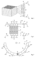
- the figure 7 is a top view illustrating a radiation detection device 50 having a curved wall 51 consisting of a succession of chambers 52 each of which contains the pressurized gas detectors.
- the wall 51 is for example made of metal sheets having a thickness of the order of 3 mm.
- Each chamber 52 comprises a radiation detector as described above, an example 56 of which is shown.
- the slices of the same level of neighboring detectors are coupled to each other, for example in pairs, to provide combined outputs, a level of these outputs being designated by references 58-1 to 58-6 in figure 7 . This further reduces the number of output lines.
- Such a device can be used in a scientific application to detect the direction of radiation from a source 54 in the center of a partial cylinder consisting of the curved wall 51.
Description
La présente invention concerne le domaine des détecteurs de particules ou de rayonnements ionisants, et en particulier des détecteurs de neutrons, de rayons y ou X.The present invention relates to the field of detectors for particles or ionizing radiation, and in particular neutron, γ or X-ray detectors.
La
Le mélange gazeux contenu dans le tube est prévu pour être ionisé par les particules que l'on veut détecter, soit directement, soit après conversion en particules ionisantes. Par exemple, on peut utiliser pour la détection de neutrons un mélange de CF4 et de 3He dans lequel le 3He joue le rôle de convertisseur, et le CF4 celui de gaz d'arrêt des deux particules ionisantes (proton et triton) émises après capture d'un neutron par un atome de 3He.The gaseous mixture contained in the tube is intended to be ionized by the particles that are to be detected, either directly or after conversion into ionizing particles. For example, a mixture of CF 4 and 3 He in which the 3 He acts as a converter can be used for the detection of neutrons, and the CF 4 as the gas for stopping both particles. ionizing (proton and triton) emitted after neutron capture by a 3 He atom.
Pour mesurer la position de l'impact le long du tube on utilise couramment un procédé dit par division de charge. Le fil est alors résistif. Le circuit de mesure comprend une électronique de lecture permettant une mesure d'amplitude de signal de charge à chaque extrémité du fil. Ce mode de détection est toujours complexe. Un autre mode de fonctionnement, dit "de comptage", utilise une électronique basée sur la comparaison, par rapport à une tension de référence, du signal mesuré à une seule extrémité du fil. Ce mode de détection est généralement imprécis dans ses implémentations courantes.To measure the position of the impact along the tube is commonly used a process said division of charge. The wire is then resistive. The measurement circuit includes a read electronics for load signal amplitude measurement at each end of the wire. This detection mode is always complex. Another mode of operation, called "counting", uses electronics based on the comparison, with respect to a reference voltage, of the signal measured at one end of the wire. This detection mode is generally imprecise in its current implementations.
L'uniformité de réponse du détecteur est affectée par l'imprécision de centrage du fil à l'intérieur du tube, et ce centrage est difficile à réaliser. La difficulté de centrage du fil 8 limite le gain d'amplification maximum avec lequel peut fonctionner le détecteur, ce qui a des conséquences directes sur les performances du détecteur (résolution en énergie et en position).The uniformity of response of the detector is affected by the inaccuracy of centering of the wire inside the tube, and this centering is difficult to achieve. The difficulty of centering the wire 8 limits the maximum amplification gain with which the detector can operate, which has a direct impact on the performance of the detector (resolution in energy and in position).
Un détecteur de rayonnement ionisant est classiquement formé de plusieurs détecteurs élémentaires dont les tubes sont juxtaposés. Le fonctionnement d'un détecteur dépend de la qualité et de la pression du mélange gazeux qu'il contient. En outre, lorsque plusieurs détecteurs doivent être utilisés ensemble avec un minimum d'espace entre les tubes, typiquement 10 mm, il est difficile d'assurer la continuité du blindage électromagnétique entre l'enveloppe du tube et le circuit de mesure 9 sans dépasser le diamètre extérieur du tube, ce qui a pour effet de créer des espaces morts entre les détecteurs, d'où une perte de sensibilité de l'ensemble.An ionizing radiation detector is conventionally formed of several elementary detectors whose tubes are juxtaposed. The operation of a detector depends on the quality and pressure of the gas mixture it contains. In addition, when several detectors must be used together with a minimum of space between the tubes, typically 10 mm, it is difficult to ensure the continuity of the electromagnetic shielding between the tube casing and the measuring circuit 9 without exceeding the outer diameter of the tube, which has the effect of creating dead spaces between the detectors, resulting in a loss of sensitivity of the whole.
Un objet d'un mode de réalisation de la présente invention est de prévoir un assemblage simple et peu coûteux à réaliser de détecteurs sensibles à des rayonnements ionisants.An object of an embodiment of the present invention is to provide a simple and inexpensive assembly to make detectors sensitive to ionizing radiation.
Un objet d'un mode de réalisation de la présente invention est de prévoir un détecteur de rayonnement ionisant particulièrement adapté à utiliser des couches minces de matériau convertisseur produisant des particules chargées.An object of an embodiment of the present invention is to provide an ionizing radiation detector particularly suitable for using thin layers of converter material producing charged particles.
Un autre objet d'un mode de réalisation de la présente invention est de prévoir un détecteur adapté à détecter la présence ou l'absence de rayonnement ionisant, avec ou sans localisation du point de conversion dudit rayonnement.Another object of an embodiment of the present invention is to provide a detector adapted to detect the presence or absence of ionizing radiation, with or without location of the conversion point of said radiation.
Pour atteindre ces objets, un mode de réalisation de la présente invention prévoit un détecteur de rayonnement ionisant comprenant une pluralité de tubes conducteurs disposés parallèlement contenant un mélange gazeux, un fil conducteur étant tendu au centre de chaque tube et propre à être polarisé par rapport à celui-ci, dans lequel chaque tube est divisé en sections longitudinales électriquement isolées, toutes les sections de tubes d'une même tranche transversale étant formées d'un quadrillage de lames connectées électriquement et chaque ensemble de sections d'une même tranche comprenant un moyen de connexion à un circuit de détection.To achieve these objects, an embodiment of the present invention provides an ionizing radiation detector comprising a plurality of parallel conductor tubes containing a gaseous mixture, a conductive wire being tensioned in the center of each tube and adapted to be polarized relative to the latter, in which each tube is divided into electrically insulated longitudinal sections, all the sections of tubes of the same transverse slice being formed of a grid of electrically connected slats and each set of sections of the same slice comprising a means connecting to a detection circuit.
Selon un mode de réalisation de la présente invention, le quadrillage de lames de chaque tranche est lié à un cadre.According to one embodiment of the present invention, the grid of blades of each slice is linked to a frame.
Selon un mode de réalisation de la présente invention, chaque lame est revêtue d'une couche contenant un produit convertisseur de rayonnement générant des ions en réponse à un rayonnant ionisant.According to an embodiment of the present invention, each blade is coated with a layer containing a radiation converting product generating ions in response to an ionizing radiation.
Selon un mode de réalisation de la présente invention, le produit convertisseur contient du bore-10.According to one embodiment of the present invention, the converter product contains boron-10.
Selon un mode de réalisation de la présente invention, le mélange de gaz est un mélange de gaz sous pression contenant du BF3.According to one embodiment of the present invention, the gas mixture is a mixture of pressurized gas containing BF 3 .
Selon un mode de réalisation de la présente invention, les lames sont en aluminium.According to one embodiment of the present invention, the blades are made of aluminum.
Selon un mode de réalisation de la présente invention, un premier groupe de lames du quadrillage comprend des fentes qui coopèrent avec des fentes d'un second groupe de lames du quadrillage orthogonal au premier groupe.According to an embodiment of the present invention, a first group of grid blades comprises slits which cooperate with slots of a second group of blades of the grid orthogonal to the first group.
Selon un mode de réalisation de la présente invention, le circuit de détection comprend une pluralité de résistances couplées en série entre des premier et second amplificateurs, les noeuds entre les résistances étant couplés aux moyens de connexion des tranches respectives.According to an embodiment of the present invention, the detection circuit comprises a plurality of resistors coupled in series between first and second amplifiers, the nodes between the resistors being coupled to the connection means of the respective slots.
Selon un mode de réalisation de la présente invention, chacun des tubes comprend des moyens pour connecter le fil conducteur du tube à un autre circuit de détection.According to one embodiment of the present invention, each of the tubes comprises means for connecting the conductive wire of the tube to another detection circuit.
Selon un mode de réalisation de la présente invention, les fils conducteurs d'un groupe de tubes sont couplés les uns aux autres.According to one embodiment of the present invention, the conducting wires of a group of tubes are coupled to each other.
Selon un mode de réalisation de la présente invention, l'autre circuit de détection comprend une pluralité de résistances, couplées en série entre des troisième et quatrième amplificateurs, les noeuds entre les résistances étant couplés aux moyens de connexion des tubes ou des groupes de tubes respectifs.According to an embodiment of the present invention, the other detection circuit comprises a plurality of resistors coupled in series between third and fourth amplifiers, the nodes between the resistors being coupled to the connection means of the tubes or groups of tubes. respectively.
Selon un mode de réalisation de la présente invention, le détecteur est prévu pour détecter des neutrons.According to one embodiment of the present invention, the detector is provided for detecting neutrons.
Un mode de réalisation de la présente invention prévoit un dispositif pour détecter un rayonnement ionisant comprenant une pluralité de détecteurs tels que ci-dessus disposés côte à côte.An embodiment of the present invention provides a device for detecting ionizing radiation comprising a plurality of detectors as above arranged side by side.
Selon un mode de réalisation de la présente invention, chacun de la pluralité de détecteurs est disposé dans l'une correspondante d'une succession de chambres formant une portion de cylindre.According to an embodiment of the present invention, each of the plurality of detectors is disposed in a corresponding one of a succession of chambers forming a cylinder portion.
Ces objets, caractéristiques et avantages, ainsi que d'autres seront exposés en détail dans la description suivante de modes de réalisation particuliers faite à titre non-limitatif en relation avec les figures jointes parmi lesquelles :
- la
figure 1 , décrite précédemment, représente le schéma d'un élément d'un détecteur de rayonnement classique ; - la
figure 2 représente de façon schématique une vue de face d'un détecteur de rayonnement ionisant selon un mode de réalisation de la présente invention ; - la
figure 3 est un schéma destiné à préciser les axes de coordonnées utilisés dans la présente description ; - la
figure 4 représente un mode de réalisation d'un élément d'un détecteur selon un mode de réalisation de la présente invention ; - la
figure 5 représente plus en détail un détecteur de rayonnement selon un mode de réalisation de la présente invention ; - la
figure 6 représente schématiquement et plus en détail une vue de dessus d'une tranche supérieure du détecteur de rayonnement de lafigure 5 selon un mode de réalisation de la présente invention ; et - la
figure 7 représente un dispositif de détection de rayonnement selon un mode de réalisation de la présente invention.
- the
figure 1 , described above, represents the schematic diagram of an element of a conventional radiation detector; - the
figure 2 schematically shows a front view of an ionizing radiation detector according to an embodiment of the present invention; - the
figure 3 is a diagram for specifying the coordinate axes used in the present description; - the
figure 4 represents an embodiment of an element of a detector according to an embodiment of the present invention; - the
figure 5 shows in more detail a radiation detector according to an embodiment of the present invention; - the
figure 6 shows schematically and in more detail a top view of an upper edge of the radiation detector of thefigure 5 according to an embodiment of the present invention; and - the
figure 7 represents a radiation detection device according to an embodiment of the present invention.
Comme le représente la
Pour les orientations des axes x, y et z, on se référera à la
Ainsi, avec les circuits 16 et 18, on pourra déterminer avec précision la cellule au niveau de laquelle a eu lieu une conversion d'un rayonnement, par exemple d'un neutron.Thus, with the
L'ensemble de la structure est disposé dans une enceinte remplie d'un gaz propre à être ionisé. Le gaz est par exemple sous pression. D'autre part, le produit convertisseur réagissant au rayonnement ionisant (par exemple des neutrons), peut être, comme dans l'art antérieur décrit précédemment, un gaz tel que de l'hélium-3 ou du BF3. Il pourra aussi s'agir d'un matériau réactif déposé en couche mince, seul ou en combinaison avec un autre matériau, sur les parois de chaque tube, ou bien encore de la combinaison d'hélium-3 ou de BF3 et de couches minces de matériau réactif. Ce matériau réactif pourra être du bore-10, susceptible d'interagir avec un neutron pour fournir du lithium-7 et une particule alpha-4. D'autres produits susceptibles d'être utilisés sont connus dans la technique. Il pourra par exemple s'agir d'isotopes de gadolinium ou de lithium, ces matériaux étant déposés en couches minces sur les parois du tube et/ou sur la bande centrale. Il est intéressant d'utiliser de tels matériaux convertisseurs car l'hélium 3 est extrêmement coûteux et difficilement disponible. De façon avantageuse, l'utilisation de BF3 gazeux et d'un revêtement de bore sur les parois de chaque tube conduit à un double effet pour la détection de neutrons. Par contre, il est très difficile de revêtir les parois internes d'un tube d'une couche contenant un tel matériau.The entire structure is disposed in an enclosure filled with a clean gas to be ionized. The gas is for example under pressure. On the other hand, the converter product reacting to the ionizing radiation (for example neutrons), may be, as in the prior art described above, a gas such as helium-3 or BF 3 . It may also be a reactive material deposited in a thin layer, alone or in combination with another material, on the walls of each tube, or else the combination of helium-3 or BF 3 and layers thin reactive material. This reactive material may be boron-10, capable of interacting with a neutron to provide lithium-7 and an alpha-4 particle. Other products that may be used are known in the art. It may for example be isotopes of gadolinium or lithium, these materials being deposited in thin layers on the walls of the tube and / or on the central strip. It is interesting to use such converter materials because
La structure proposée ici permet, comme on le verra ci-après, de réaliser très simplement le revêtement des parois.The structure proposed here makes it possible, as will be seen below, to realize very simply the coating of the walls.
La
On notera que les plaques, ou lames, 23 et 25 pourront sans difficulté être enduites d'un produit convertisseur avant montage, ce qui simplifie beaucoup cette enduction ou dépôt. Ainsi, quand un rayonnement ionisant interagit au niveau de l'une des cellules, il en résulte un signal électrique sur le conducteur central et sur la tranche. On a en outre représenté en
On comprendra qu'il ne s'agit là que d'un exemple de réalisation de la présente invention. On pourra utiliser toute structure en nid d'abeille, comportant par exemple des cellules de forme hexagonale ou autre. En outre, on notera que le cadre 21 comprenant des fentes 22 et 27 est optionnel. A titre de variante, un empilement de plaques 23 et 25 pourrait être fixé dans une chambre comme cela est décrit plus en détail ci-après.It will be understood that this is only an exemplary embodiment of the present invention. It will be possible to use any honeycomb structure, comprising, for example, cells of hexagonal shape or the like. In addition, it should be noted that the 21 including
On a indiqué précédemment que chaque section et chaque fil traversant un ensemble de sections alignées verticalement sont reliés à un système de polarisation et de détection de sorte que les fils constituent des anodes et les parois des sections d'une tranche des cathodes permettant d'attirer les gaz ionisés produits par la conversion du bombardement ionisant. On a également indiqué que chaque fil et chaque tranche de cellules était relié par un conducteur séparé pour pouvoir reconnaître la cellule au niveau de laquelle le rayonnement ionisant a été converti. En fait, cette discrimination des cellules n'est pas toujours nécessaire. Dans certains cas, on veut simplement, par exemple dans des dispositifs de sécurité d'aéroport, savoir si un bagage ou un conteneur contient des produits radioactifs émettant des neutrons. Il suffira alors de relier ensemble tous les fils et toutes les sections pour disposer d'un dispositif très simple à utiliser, avec peu de lignes de sortie.It has been indicated previously that each section and each wire passing through a set of vertically aligned sections are connected to a polarization and detection system so that the wires constitute anodes and the walls of the cathode wafer sections to attract the ionized gases produced by the conversion of ionizing bombardment. It has also been indicated that each wire and cell slice is connected by a separate conductor to recognize the cell at which the ionizing radiation has been converted. In fact, this discrimination of the cells is not always necessary. In some cases, one simply wants, for example in airport security devices, to know if a piece of luggage or a container contains radioactive products emitting neutrons. It will be enough then to connect together all the wires and all the sections to have a very simple device to use, with few lines of exit.
A titre d'exemple de dimensions, chaque section pourra avoir un côté de l'ordre de 2 cm et une hauteur de l'ordre de 2 cm et l'ensemble de la structure pourra avoir une hauteur de l'ordre de 3 m. L'homme de l'art saura adapter ces dimensions à ses besoins.As an example of dimensions, each section may have a side of the order of 2 cm and a height of the order of 2 cm and the entire structure may have a height of about 3 m. Those skilled in the art will be able to adapt these dimensions to their needs.
Un avantage de l'utilisation d'une structure en quadrillage est que la section de chaque tube peut avoir de petites dimensions. Par exemple, plutôt que d'être égale à 2 cm comme cela a été décrit ci-dessus, la longueur latérale de chaque section de chaque tube rectangulaire est par exemple seulement de 4 à 10 mm. Ceci permet que les électrons résultant d'une réaction aient un faible temps de vol et donc qu'une pression relativement élevée de gaz puisse être utilisée dans le tube, par exemple supérieure à 2.105 Pa. Ceci est particulièrement avantageux quand le gaz est du BF3. En outre, une telle structure en quadrillage peut avantageusement être constituée de plaques ou lames 23, 25 en aluminium ayant par exemple une épaisseur de 0,5 mm ou moins.An advantage of using a grid structure is that the section of each tube can have small dimensions. For example, rather than being 2 cm as described above, the lateral length of each section of each rectangular tube is for example only 4 to 10 mm. This allows the electrons resulting from a reaction to have a short flight time and thus a relatively high gas pressure can be used in the tube, for example greater than 2.10 5 Pa. This is particularly advantageous when the gas is from BF 3 . In addition, such a grid structure can advantageously be consisting of plates or
La
Un avantage de l'utilisation du réseau de résistances 30 de la
La
En outre ou à titre de variante, un ou plusieurs réseaux résistifs peuvent être utilisés pour réduire le nombre de connexions aux fils. La
La
Dans un mode de réalisation, les tranches du même niveau de détecteurs voisins sont couplées les unes aux autres, par exemple par paires, pour fournir des sorties combinées, un niveau de ces sorties étant désigné par les références 58-1 à 58-6 en
Un tel dispositif peut être utilisé dans une application scientifique pour détecter la direction d'un rayonnement provenant d'une source 54 au centre d'un cylindre partiel constitué de la paroi courbe 51.Such a device can be used in a scientific application to detect the direction of radiation from a
Des modes de réalisation particuliers de la présente invention ont été décrits. Diverses variantes et modifications apparaîtront à l'homme de l'art. En particulier, les tranches superposées pourront définir diverses formes d'alvéoles et être constituées de diverses manières.Particular embodiments of the present invention have been described. Various variations and modifications will be apparent to those skilled in the art. In particular, the superimposed slices can define various shapes of cells and be constituted in various ways.
Claims (14)
- An ionizing radiation detector comprising a plurality of conductive tubes arranged in parallel containing a gas mixture, a conductive wire (14-1, ... 14-n) being pulled tight at the center of each tube and capable of being biased with respect thereto, wherein each tube is divided into electrically isolated longitudinal sections (12-ijk), each group of sections of a same slice comprising means for connection to a detection circuit (18), characterized in that all the tube sections of a same transverse slice are formed of a grid of electrically connected blades (23, 25).
- The detector of claim 1, wherein said grid of blades of each slice is connected to a frame (21).
- The detector of claim 1 or 2, wherein each blade is coated with a layer containing a radiation conversion product generating ions as a response to an ionizing radiation.
- The detector of claim 3, wherein the conversion product is boron-10.
- The detector of any of claims 1 to 4, wherein said gas mixture is a pressurized gas mixture comprising BF3.
- The detector of any of claims 1 to 5, wherein said blades are made of aluminum.
- The detector of any of claims 1 to 6, wherein a first group of blades (23) of said grid comprise slots (24) which cooperate with slots (27) of a second group of blades of said grid orthogonal with respect to said first group.
- The detector of any of claims 1 to 7, wherein said detection circuit (18) comprises a plurality of resistors (30-1 to 30-7) coupled in series between first and second amplifiers (32, 34), the nodes between said resistors being coupled to the connection means of respective slices.
- The detector of any of claims 1 to 8, wherein each of said tubes comprises means for connecting the conductive wire of said tube to a further detection circuit (16).
- The detector of claim 9, wherein the conductive wires of a group of said tubes are coupled together.
- The detector of claim 9 or 10, wherein said further detection circuit (16) comprises a plurality of resistors (36-1 to 36-3, 42-1 to 42-3) coupled in series between third and fourth amplifiers (44, 46), the nodes between said resistors being coupled to the connection means of respective tubes or groups of tubes.
- The detector of any of claims 1 to 11, wherein the detector is arranged to detect neutrons.
- An apparatus for detecting ionizing radiation comprising a plurality of the detectors of any of claims 1 to 12 positioned side by side.
- The apparatus of claim 13, wherein said plurality of detectors are each positioned in a corresponding one of a series of chambers forming a segment of a cylinder.
Priority Applications (1)
| Application Number | Priority Date | Filing Date | Title |
|---|---|---|---|
| US13/038,915 US8481957B2 (en) | 2010-03-02 | 2011-03-02 | Ionizing radiation detector |
Applications Claiming Priority (1)
| Application Number | Priority Date | Filing Date | Title |
|---|---|---|---|
| FR1051502A FR2957188B1 (en) | 2010-03-02 | 2010-03-02 | IONIZING RADIATION DETECTOR |
Publications (2)
| Publication Number | Publication Date |
|---|---|
| EP2363876A1 EP2363876A1 (en) | 2011-09-07 |
| EP2363876B1 true EP2363876B1 (en) | 2015-04-29 |
Family
ID=42979826
Family Applications (1)
| Application Number | Title | Priority Date | Filing Date |
|---|---|---|---|
| EP20110156361 Active EP2363876B1 (en) | 2010-03-02 | 2011-03-01 | Ionising radiation detector |
Country Status (4)
| Country | Link |
|---|---|
| US (1) | US8481957B2 (en) |
| EP (1) | EP2363876B1 (en) |
| JP (1) | JP2011191295A (en) |
| FR (1) | FR2957188B1 (en) |
Families Citing this family (2)
| Publication number | Priority date | Publication date | Assignee | Title |
|---|---|---|---|---|
| DE102012108766A1 (en) * | 2012-09-18 | 2014-03-20 | CDT Cascade Detector Technologies GmbH | Neutron detector unit as well as neutron detector arrangement |
| US9847215B2 (en) * | 2014-11-08 | 2017-12-19 | Jefferson Science Associates, Llc | Method for detecting and distinguishing between specific types of environmental radiation using a high pressure ionization chamber with pulse-mode readout |
Family Cites Families (10)
| Publication number | Priority date | Publication date | Assignee | Title |
|---|---|---|---|---|
| FR943262A (en) * | 1946-03-14 | 1949-03-03 | Texaco Development Corp | Radiation Detector Improvements |
| US4447727A (en) * | 1981-06-30 | 1984-05-08 | Irt Corporation | Large area neutron proportional counter and portal monitor detector |
| US5071381A (en) * | 1990-03-07 | 1991-12-10 | Advanced Interconnect Technology Inc. | Process for the manufacture of straw tube drift chambers |
| US5734689A (en) * | 1996-01-29 | 1998-03-31 | The United States Of America As Represented By The Secretary Of The Navy | Thermal neutron detector |
| DE19907042A1 (en) * | 1999-02-19 | 2000-08-31 | Gsf Forschungszentrum Umwelt | Modular ionization detector |
| AU2003299556A1 (en) * | 2002-11-13 | 2004-06-03 | Proportional Technologies, Inc. | Boron coated straw neutron detector |
| US7233007B2 (en) * | 2004-03-01 | 2007-06-19 | Nova Scientific, Inc. | Radiation detectors and methods of detecting radiation |
| US20100012581A1 (en) * | 2006-06-01 | 2010-01-21 | Ben-Gurion University Of The Negev Research And Development Authority | Denitrification treatment system and method |
| US7633062B2 (en) * | 2006-10-27 | 2009-12-15 | Los Alamos National Security, Llc | Radiation portal monitor system and method |
| US7858949B2 (en) * | 2008-07-18 | 2010-12-28 | Brookhaven Science Associates, Llc | Multi-anode ionization chamber |
-
2010
- 2010-03-02 FR FR1051502A patent/FR2957188B1/en not_active Expired - Fee Related
-
2011
- 2011-03-01 EP EP20110156361 patent/EP2363876B1/en active Active
- 2011-03-02 US US13/038,915 patent/US8481957B2/en active Active
- 2011-03-02 JP JP2011044954A patent/JP2011191295A/en active Pending
Also Published As
| Publication number | Publication date |
|---|---|
| FR2957188A1 (en) | 2011-09-09 |
| FR2957188B1 (en) | 2012-08-17 |
| US8481957B2 (en) | 2013-07-09 |
| JP2011191295A (en) | 2011-09-29 |
| EP2363876A1 (en) | 2011-09-07 |
| US20110215251A1 (en) | 2011-09-08 |
Similar Documents
| Publication | Publication Date | Title |
|---|---|---|
| EP0855086B1 (en) | High-resolution position detector for high-flux ionising particle streams | |
| EP0678896B1 (en) | Low dose ionizing X- or gamma-ray medical imaging device | |
| EP0810631B1 (en) | High resolution radiographic imaging device | |
| EP0742954A1 (en) | Ionising radiation detector having proportional microcounters | |
| EP0007842B1 (en) | Device for the detection and localization of radiation | |
| EP0515261B1 (en) | Ceramic electron multiplying structure especially for photomultiplier and its manufacturing procedure | |
| EP2363876B1 (en) | Ionising radiation detector | |
| WO1993003495A1 (en) | Ionizing radiation gas detector | |
| EP0064913B1 (en) | X-rays multidetector | |
| FR2951580A1 (en) | RADIOGRAPHIC IMAGING DEVICE AND DETECTOR FOR A RADIOGRAPHIC IMAGING DEVICE | |
| EP0010474B1 (en) | Radiation detector | |
| EP0593333A1 (en) | Detector cell, detector, sensor for spectroscope | |
| FR2705791A1 (en) | X-ray detector for obtaining selective energy responses | |
| FR2504278A1 (en) | X-RAY DETECTOR | |
| WO2008129159A1 (en) | Electron multiplication device and system for detecting ionising radiation | |
| EP1343194A1 (en) | Radiation detectors and autoradiographic imaging devices comprising such detectors | |
| WO2003010793A1 (en) | Ionising radiation detector with solid radiation conversion plate, and method for making same | |
| FR2514557A1 (en) | MINIATURE MAGNETIC SPECTROMETER WITH COAXIAL STRUCTURE | |
| EP0441853B1 (en) | Method and device for the bimensional localization of neutral particles, particularly for low counting ratios | |
| WO2022180085A1 (en) | Device for measuring a secondary vacuum pressure, and on-board system for measuring a residual vacuum pressure | |
| EP1131843A1 (en) | Gas-filled photon detector | |
| WO1997004335A1 (en) | Transparent position-sensitive particle detector | |
| FR3076948A1 (en) | PHOTON X DETECTOR IN THE ENERGY RANGE 1 TO 5 KEV | |
| EP3086139A1 (en) | Holding rod of a spherical detection device | |
| WO1993022792A1 (en) | Device for two-dimensionally sensing and locating neutrons |
Legal Events
| Date | Code | Title | Description |
|---|---|---|---|
| PUAI | Public reference made under article 153(3) epc to a published international application that has entered the european phase |
Free format text: ORIGINAL CODE: 0009012 |
|
| AK | Designated contracting states |
Kind code of ref document: A1 Designated state(s): AL AT BE BG CH CY CZ DE DK EE ES FI FR GB GR HR HU IE IS IT LI LT LU LV MC MK MT NL NO PL PT RO RS SE SI SK SM TR |
|
| AX | Request for extension of the european patent |
Extension state: BA ME |
|
| 17P | Request for examination filed |
Effective date: 20111221 |
|
| GRAP | Despatch of communication of intention to grant a patent |
Free format text: ORIGINAL CODE: EPIDOSNIGR1 |
|
| INTG | Intention to grant announced |
Effective date: 20141117 |
|
| GRAS | Grant fee paid |
Free format text: ORIGINAL CODE: EPIDOSNIGR3 |
|
| GRAA | (expected) grant |
Free format text: ORIGINAL CODE: 0009210 |
|
| AK | Designated contracting states |
Kind code of ref document: B1 Designated state(s): AL AT BE BG CH CY CZ DE DK EE ES FI FR GB GR HR HU IE IS IT LI LT LU LV MC MK MT NL NO PL PT RO RS SE SI SK SM TR |
|
| REG | Reference to a national code |
Ref country code: GB Ref legal event code: FG4D Free format text: NOT ENGLISH |
|
| REG | Reference to a national code |
Ref country code: CH Ref legal event code: EP |
|
| REG | Reference to a national code |
Ref country code: AT Ref legal event code: REF Ref document number: 724849 Country of ref document: AT Kind code of ref document: T Effective date: 20150515 |
|
| REG | Reference to a national code |
Ref country code: IE Ref legal event code: FG4D Free format text: LANGUAGE OF EP DOCUMENT: FRENCH |
|
| REG | Reference to a national code |
Ref country code: DE Ref legal event code: R096 Ref document number: 602011016035 Country of ref document: DE Effective date: 20150611 |
|
| REG | Reference to a national code |
Ref country code: SE Ref legal event code: TRGR |
|
| REG | Reference to a national code |
Ref country code: NL Ref legal event code: VDEP Effective date: 20150429 |
|
| REG | Reference to a national code |
Ref country code: AT Ref legal event code: MK05 Ref document number: 724849 Country of ref document: AT Kind code of ref document: T Effective date: 20150429 |
|
| REG | Reference to a national code |
Ref country code: LT Ref legal event code: MG4D |
|
| PG25 | Lapsed in a contracting state [announced via postgrant information from national office to epo] |
Ref country code: NL Free format text: LAPSE BECAUSE OF FAILURE TO SUBMIT A TRANSLATION OF THE DESCRIPTION OR TO PAY THE FEE WITHIN THE PRESCRIBED TIME-LIMIT Effective date: 20150429 |
|
| PG25 | Lapsed in a contracting state [announced via postgrant information from national office to epo] |
Ref country code: FI Free format text: LAPSE BECAUSE OF FAILURE TO SUBMIT A TRANSLATION OF THE DESCRIPTION OR TO PAY THE FEE WITHIN THE PRESCRIBED TIME-LIMIT Effective date: 20150429 Ref country code: NO Free format text: LAPSE BECAUSE OF FAILURE TO SUBMIT A TRANSLATION OF THE DESCRIPTION OR TO PAY THE FEE WITHIN THE PRESCRIBED TIME-LIMIT Effective date: 20150729 Ref country code: PT Free format text: LAPSE BECAUSE OF FAILURE TO SUBMIT A TRANSLATION OF THE DESCRIPTION OR TO PAY THE FEE WITHIN THE PRESCRIBED TIME-LIMIT Effective date: 20150831 Ref country code: ES Free format text: LAPSE BECAUSE OF FAILURE TO SUBMIT A TRANSLATION OF THE DESCRIPTION OR TO PAY THE FEE WITHIN THE PRESCRIBED TIME-LIMIT Effective date: 20150429 Ref country code: LT Free format text: LAPSE BECAUSE OF FAILURE TO SUBMIT A TRANSLATION OF THE DESCRIPTION OR TO PAY THE FEE WITHIN THE PRESCRIBED TIME-LIMIT Effective date: 20150429 Ref country code: HR Free format text: LAPSE BECAUSE OF FAILURE TO SUBMIT A TRANSLATION OF THE DESCRIPTION OR TO PAY THE FEE WITHIN THE PRESCRIBED TIME-LIMIT Effective date: 20150429 |
|
| PG25 | Lapsed in a contracting state [announced via postgrant information from national office to epo] |
Ref country code: LV Free format text: LAPSE BECAUSE OF FAILURE TO SUBMIT A TRANSLATION OF THE DESCRIPTION OR TO PAY THE FEE WITHIN THE PRESCRIBED TIME-LIMIT Effective date: 20150429 Ref country code: AT Free format text: LAPSE BECAUSE OF FAILURE TO SUBMIT A TRANSLATION OF THE DESCRIPTION OR TO PAY THE FEE WITHIN THE PRESCRIBED TIME-LIMIT Effective date: 20150429 Ref country code: IS Free format text: LAPSE BECAUSE OF FAILURE TO SUBMIT A TRANSLATION OF THE DESCRIPTION OR TO PAY THE FEE WITHIN THE PRESCRIBED TIME-LIMIT Effective date: 20150829 Ref country code: RS Free format text: LAPSE BECAUSE OF FAILURE TO SUBMIT A TRANSLATION OF THE DESCRIPTION OR TO PAY THE FEE WITHIN THE PRESCRIBED TIME-LIMIT Effective date: 20150429 Ref country code: GR Free format text: LAPSE BECAUSE OF FAILURE TO SUBMIT A TRANSLATION OF THE DESCRIPTION OR TO PAY THE FEE WITHIN THE PRESCRIBED TIME-LIMIT Effective date: 20150730 |
|
| PG25 | Lapsed in a contracting state [announced via postgrant information from national office to epo] |
Ref country code: DK Free format text: LAPSE BECAUSE OF FAILURE TO SUBMIT A TRANSLATION OF THE DESCRIPTION OR TO PAY THE FEE WITHIN THE PRESCRIBED TIME-LIMIT Effective date: 20150429 Ref country code: EE Free format text: LAPSE BECAUSE OF FAILURE TO SUBMIT A TRANSLATION OF THE DESCRIPTION OR TO PAY THE FEE WITHIN THE PRESCRIBED TIME-LIMIT Effective date: 20150429 |
|
| REG | Reference to a national code |
Ref country code: DE Ref legal event code: R097 Ref document number: 602011016035 Country of ref document: DE |
|
| PG25 | Lapsed in a contracting state [announced via postgrant information from national office to epo] |
Ref country code: CZ Free format text: LAPSE BECAUSE OF FAILURE TO SUBMIT A TRANSLATION OF THE DESCRIPTION OR TO PAY THE FEE WITHIN THE PRESCRIBED TIME-LIMIT Effective date: 20150429 Ref country code: SK Free format text: LAPSE BECAUSE OF FAILURE TO SUBMIT A TRANSLATION OF THE DESCRIPTION OR TO PAY THE FEE WITHIN THE PRESCRIBED TIME-LIMIT Effective date: 20150429 Ref country code: PL Free format text: LAPSE BECAUSE OF FAILURE TO SUBMIT A TRANSLATION OF THE DESCRIPTION OR TO PAY THE FEE WITHIN THE PRESCRIBED TIME-LIMIT Effective date: 20150429 Ref country code: RO Free format text: LAPSE BECAUSE OF NON-PAYMENT OF DUE FEES Effective date: 20150429 |
|
| PLBE | No opposition filed within time limit |
Free format text: ORIGINAL CODE: 0009261 |
|
| STAA | Information on the status of an ep patent application or granted ep patent |
Free format text: STATUS: NO OPPOSITION FILED WITHIN TIME LIMIT |
|
| REG | Reference to a national code |
Ref country code: FR Ref legal event code: PLFP Year of fee payment: 6 |
|
| 26N | No opposition filed |
Effective date: 20160201 |
|
| PG25 | Lapsed in a contracting state [announced via postgrant information from national office to epo] |
Ref country code: IT Free format text: LAPSE BECAUSE OF FAILURE TO SUBMIT A TRANSLATION OF THE DESCRIPTION OR TO PAY THE FEE WITHIN THE PRESCRIBED TIME-LIMIT Effective date: 20150429 |
|
| PG25 | Lapsed in a contracting state [announced via postgrant information from national office to epo] |
Ref country code: SI Free format text: LAPSE BECAUSE OF FAILURE TO SUBMIT A TRANSLATION OF THE DESCRIPTION OR TO PAY THE FEE WITHIN THE PRESCRIBED TIME-LIMIT Effective date: 20150429 |
|
| PG25 | Lapsed in a contracting state [announced via postgrant information from national office to epo] |
Ref country code: BE Free format text: LAPSE BECAUSE OF NON-PAYMENT OF DUE FEES Effective date: 20160331 |
|
| PG25 | Lapsed in a contracting state [announced via postgrant information from national office to epo] |
Ref country code: LU Free format text: LAPSE BECAUSE OF FAILURE TO SUBMIT A TRANSLATION OF THE DESCRIPTION OR TO PAY THE FEE WITHIN THE PRESCRIBED TIME-LIMIT Effective date: 20160301 Ref country code: MC Free format text: LAPSE BECAUSE OF FAILURE TO SUBMIT A TRANSLATION OF THE DESCRIPTION OR TO PAY THE FEE WITHIN THE PRESCRIBED TIME-LIMIT Effective date: 20150429 |
|
| REG | Reference to a national code |
Ref country code: CH Ref legal event code: PL |
|
| REG | Reference to a national code |
Ref country code: IE Ref legal event code: MM4A |
|
| PG25 | Lapsed in a contracting state [announced via postgrant information from national office to epo] |
Ref country code: IE Free format text: LAPSE BECAUSE OF NON-PAYMENT OF DUE FEES Effective date: 20160301 Ref country code: CH Free format text: LAPSE BECAUSE OF NON-PAYMENT OF DUE FEES Effective date: 20160331 Ref country code: LI Free format text: LAPSE BECAUSE OF NON-PAYMENT OF DUE FEES Effective date: 20160331 |
|
| REG | Reference to a national code |
Ref country code: FR Ref legal event code: PLFP Year of fee payment: 7 |
|
| PG25 | Lapsed in a contracting state [announced via postgrant information from national office to epo] |
Ref country code: MT Free format text: LAPSE BECAUSE OF FAILURE TO SUBMIT A TRANSLATION OF THE DESCRIPTION OR TO PAY THE FEE WITHIN THE PRESCRIBED TIME-LIMIT Effective date: 20150429 |
|
| REG | Reference to a national code |
Ref country code: FR Ref legal event code: PLFP Year of fee payment: 8 |
|
| PG25 | Lapsed in a contracting state [announced via postgrant information from national office to epo] |
Ref country code: SM Free format text: LAPSE BECAUSE OF FAILURE TO SUBMIT A TRANSLATION OF THE DESCRIPTION OR TO PAY THE FEE WITHIN THE PRESCRIBED TIME-LIMIT Effective date: 20150429 Ref country code: HU Free format text: LAPSE BECAUSE OF FAILURE TO SUBMIT A TRANSLATION OF THE DESCRIPTION OR TO PAY THE FEE WITHIN THE PRESCRIBED TIME-LIMIT; INVALID AB INITIO Effective date: 20110301 Ref country code: CY Free format text: LAPSE BECAUSE OF FAILURE TO SUBMIT A TRANSLATION OF THE DESCRIPTION OR TO PAY THE FEE WITHIN THE PRESCRIBED TIME-LIMIT Effective date: 20150429 |
|
| PG25 | Lapsed in a contracting state [announced via postgrant information from national office to epo] |
Ref country code: MK Free format text: LAPSE BECAUSE OF FAILURE TO SUBMIT A TRANSLATION OF THE DESCRIPTION OR TO PAY THE FEE WITHIN THE PRESCRIBED TIME-LIMIT Effective date: 20150429 Ref country code: TR Free format text: LAPSE BECAUSE OF FAILURE TO SUBMIT A TRANSLATION OF THE DESCRIPTION OR TO PAY THE FEE WITHIN THE PRESCRIBED TIME-LIMIT Effective date: 20150429 |
|
| PG25 | Lapsed in a contracting state [announced via postgrant information from national office to epo] |
Ref country code: BG Free format text: LAPSE BECAUSE OF FAILURE TO SUBMIT A TRANSLATION OF THE DESCRIPTION OR TO PAY THE FEE WITHIN THE PRESCRIBED TIME-LIMIT Effective date: 20150429 |
|
| PG25 | Lapsed in a contracting state [announced via postgrant information from national office to epo] |
Ref country code: AL Free format text: LAPSE BECAUSE OF FAILURE TO SUBMIT A TRANSLATION OF THE DESCRIPTION OR TO PAY THE FEE WITHIN THE PRESCRIBED TIME-LIMIT Effective date: 20150429 |
|
| PGFP | Annual fee paid to national office [announced via postgrant information from national office to epo] |
Ref country code: FR Payment date: 20230330 Year of fee payment: 13 |
|
| PGFP | Annual fee paid to national office [announced via postgrant information from national office to epo] |
Ref country code: SE Payment date: 20230316 Year of fee payment: 13 Ref country code: GB Payment date: 20230324 Year of fee payment: 13 Ref country code: DE Payment date: 20230307 Year of fee payment: 13 |
|
| P01 | Opt-out of the competence of the unified patent court (upc) registered |
Effective date: 20230411 |